Introduction
A planned preventive system has been adopted in the Russian Federation Maintenance and car repair, construction and road cars... The main provisions are formulated and enshrined in the "Regulations on the maintenance and repair of the rolling stock of road transport". This Regulation shows the liver of the provided types of maintenance and repairs and operations for them, gives the standards for overhaul runs, the complexity of different types work, downtime rates in maintenance and repair, correction factors for various standards (K1-K5), depending on the specific operating conditions.
The essence of the planned preventive system is the compulsory delivery of cars and machines that have passed the standard mileage, according to the plan, to the appropriate type of maintenance in order to prevent increased wear intensity and restore the lost performance of components, assemblies and systems.
The regulation provides for:
1) Daily maintenance - EO
2) Maintenance No. 1- TO-1
3) Maintenance No. 2 - TO-2
4) Seasonal service - CO.
5) Current repairs - TR.
6) Overhaul - CD.
These types of services differ from each other in the list and the complexity of the operations performed and, of course, in the frequency.
EO - control examinations of units, mechanisms and systems. Cleaning and washing operations and refueling operations - adding oil, fluids for components and systems and mechanisms.
TO-1 - to maintain equipment in good condition, identify and prevent failures and malfunctions, work is carried out: diagnostic. fastening and adjusting, lubricating, cleaning. electrical.
TO-2-oil change or repair of parts and assemblies, except for the main ones. The term is up to one day, without the right to access the line, in accordance with the Operational Regulations.
CO-carried out twice a year, in spring and autumn, is designed to prepare transport for operation, taking into account climatic conditions, usually combined with TO-2. At the same time, increasing the standard labor intensity for additional operations, and a more thorough check of various units with forced removal from the car and machines for testing at stands and control devices.
TR - carried out on demand with lower cost standards, in equipped special areas: on lifts, inspection ditches.
KR-cars and assemblies are carried out at specialized repair enterprises or bases, with complete disassembly into individual assemblies and assemblies to parts. After washing and cleaning, troubleshooting and sorting are carried out, followed by replacement with serviceable or new parts. After completing, assembly, testing, and running-in are performed. Final assembly takes place on the main conveyor or workshop. An indispensable condition for the Kyrgyz Republic is the standard mileage: for passenger GAZ - 300 thousand km, for freight - 250 thousand km for the new generation trucks 300 thousand km
The costs of maintaining cars and machines in a technically sound condition with ensuring high operational reliability, assigned to the repair services of various ATPs, are several times higher than the costs of manufacturing new cars. Therefore, an important direction to increase the productivity of repair workers, while improving the quality of work and the efficiency of the entire production. Is the introduction the latest technologies using modern high-performance equipment, complex mechanization and automation of maintenance and repair processes for cars and machines.
1. General part
Repair depends on the degree of wear or damage to the machine or unit. Repair - a set of technological operations on a machine or unit in order to restore its operational properties to standard requirements.
There are several types of repairs:
Current repair - restoration of one or some group of its operational properties to the standard level.
Scheduled repair - a set of technological influences on a product, carried out depending on the established by the manufacturer's regulations, planned operating time in order to restore one or a certain group of its operational properties to the standard level.
Emergency current repair - a set of technological influences on the product, carried out in order to eliminate or prevent accidental failure.
Overhaul is a set of technological impacts on a product, carried out in order to restore all its operational properties, including the resource, to the standard level.
Repair methods determine the organizational forms of predominantly assembly processes when restoring a machine. These methods are divided according to several criteria.
On the basis of the preservation of the belonging of the repaired parts to a machine or unit, repairs can be made by impersonal and non-impersonal methods. With the impersonal method, the belonging of the constituent parts or units is not preserved, and with the non-impersonal method, it is preserved.
According to the organization of the execution, the repair of machines can be carried out by the aggregate method (depersonalized repair). Units are replaced with new ones or pre-repaired.
The aggregate method of repair requires a revolving fund, depends on the power of the ARP, the time spent on the exchange, and the safety stock of the units.
With an unpersonalized repair method, faulty units and parts are removed from the machine, repaired and installed on the same machine. The method is used only for machines of exceptional value or available in small quantities.
The flow method is characterized by the location of funds technical equipment in the sequence of operations of the technological process and the specialization of workplaces. The streaming method provides high productivity, efficient use of equipment and achieves high quality indicators is called industrial. It is used at most ATP enterprises.
For the organization of the repair of machines, the following methods are also used:
1) The method of specialized posts.
2) The method of universal posts.


Steering and power steering housing, cab frame, longitudinal frame beams. 3.2. Organization of maintenance and repair in motor transport enterprises The organization of maintenance and repair is based on reasonable labor intensity and duration of all work. The initial labor input is calculated for road transport ...
Operating instructions and service books supplied with the vehicle upon sale. The frequency of performance of TO-1 and TO-2 at road transport enterprises regulated by the "Regulations on the maintenance and repair of rolling stock of road transport" passenger car is, respectively, 4000 and 16000 km of run for category I of operating conditions for ...
For operation in cold or warm seasons, combining it with regular maintenance, usually with TO-2. At each maintenance of the front suspension, as well as when repairing the front suspension of a VAZ 2108, it is imperative to check the condition of the protective covers of the suspension ball joints, paying special attention to the absence of mechanical damage to the covers of the ball joints ...
Work at maintenance posts, in auxiliary departments, is selected according to technological necessity, since they are used periodically. The technological equipment required to perform work in the maintenance areas meets the basic requirements: · ensuring the performance of maintenance work in full; Ensuring all performers ...
The planned preventive system with the optimization of the frequency of maintenance and repair, as well as the maintenance, consists of a constant number of regulated maintenance activities and regulated repairs. However, the frequency of their implementation, and, consequently, the repair cycle, is determined according to the data on the actual reliability of the equipment - the actual resource of assemblies and parts. Then the parts and assemblies are grouped according to the principle of proximity of resources, and also provide the brevity of individual groups of parts.
Frequency of maintenance of cars and trailers. The planned preventive system provides for the following types of repairs: current, medium and capital.
The planned preventive system provides for the following types of repairs: current, medium and capital. Maintenance and current repairs of cars and mechanisms in mechanized columns are carried out mostly in field conditions by special repair teams using standard mobile auto repair shops that are part of the mechanical column.
The planned preventive maintenance system is compulsory and provides for the responsibility of the ATP for the timely implementation of maintenance.
The scheduled preventive maintenance system ensures the most complete utilization of the equipment due to the almost complete absence of its downtime due to the installer's waiting and a possible reduction in the labor intensity of maintenance, as in the case of an active-forced system.
The planned preventive system for organizing maintenance and repairs includes technical checks, current and major repairs.
A scheduled warning system for loading and unloading machines, including forklifts, provides for monthly and periodic maintenance. In addition to routine maintenance, seasonal maintenance is carried out; in practice, ah is combined with one of the planned activities.
A scheduled warning system for loading and unloading machines, including forklifts, provides for monthly and periodic maintenance.
The basis of the preventive maintenance system for operating time is scheduled maintenance (maintenance), which prevents equipment failures and is carried out routinely after a certain time. The main disadvantage of this TOP strategy is a significant underutilization of the resource of parts during their premature replacement during scheduled repairs. This type of TOP system increases the reliability indicator, but at the same time reduces the durability of the object's components.
With a planned preventive system, repair is reduced to the planned replacement of sets of assemblies and parts, the wear of which has not yet exceeded the established limits and allows their restoration and reuse.
According to the planned preventive system, the equipment is repaired in strict terms according to a previously developed calendar plan regardless of whether the device has broken down or not, and thereby eliminate (warn) the possibility of the device failing. The system of scheduled preventive maintenance (prophylaxis) is one of the most important conditions for ensuring the successful conduct of the technological process. The scheduled maintenance schedule is drawn up on the basis of constant inspection and checking the condition of the equipment. To quickly carry out scheduled preventive maintenance in the shop warehouse, it is necessary to have a stock of the most wearing parts of devices and materials. Preventive maintenance is carried out by the special repair shop of the plant or the repair teams of this shop. The latter is more expedient, since the brigades of this workshop, specializing in the repair of certain devices and knowing their features well, carry out repairs in a shorter time and in a more benign manner.
With the planned preventive system, the following types of repairs of cars and units are established: current, average and capital.
With a planned preventive maintenance system, the workload of the repair departments increases and the losses of the main production decrease.
A fundamental change in the planned preventive system is possible at the next step, when the product (or its elements) will be ensured to maintain operability by means of redundancy or self-recovery within the established service life. Two solutions are possible here: or the use of absolutely reliable products, the probability of failure of which for a given operating time is negligible (redundancy, increased strength); or the application of other design principles that allow for the self-healing of the product. The simplest examples of pod systems that function during a certain operating time are self-regulating mechanisms used in modern cars.
A fundamental change in the planned preventive system is possible at the next step, when the product (or its elements) will be ensured to maintain operability by means of redundancy or self-recovery within the established service life. The simplest examples of such systems, functioning for a certain operating time, are self-adjusting mechanisms used in modern cars.
The basic principles of the preventive system are set out in the current Regulation on the maintenance and repair of the rolling stock of road transport, approved by the Ministry of Transport of the RSFSR on September 20, 1984. The Regulation is mandatory for all road transport enterprises of the RSFSR and is typical for other union republics.
On the basis of a planned preventive system for design purposes, certain design standards have been established (frequency, labor intensity, duration of impacts, etc.), most of which are more progressive than the norms used to plan the activities of existing enterprises. This is quite natural, since the calculation norms are laid in the basis for the design of future enterprises.
An example is a planned preventive system for organizing maintenance and repair, which includes the planning, preparation and implementation of maintenance and repairs with a given sequence and frequency.
In accordance with the planned preventive system, the Regulation on the maintenance and repair of the rolling stock of road transport provides for: current (TR) and overhaul (CR) of a car (trailer) and its assemblies, assemblies and mechanisms.
In accordance with the unified preventive system, maintenance of cars and their components is carried out in a planned, compulsory manner, after strictly defined periods of their operation or storage, and repairs are carried out as needed, which is revealed in the process of maintenance or scheduled inspection. Although repairs are carried out as needed, they are still planned and preventive, since the need for them is revealed not after the onset of a failure, but in the process of scheduled maintenance.
The Soviet Union adopted a scheduled preventive maintenance system. The essence of this system lies in the fact that all types of maintenance are carried out compulsorily in a planned manner, after a certain mileage of the rolling stock.
The Soviet Union has adopted a scheduled preventive maintenance system for the rolling stock of road transport. The essence of this system lies in the fact that maintenance of cars is carried out without fail according to a pre-drawn up schedule and therefore it is planned. Maintenance is intended to prevent malfunctions and reduce wear and tear on parts and is therefore preventive (preventive) maintenance.
Maintenance is organized according to a planned preventive system and is carried out after a certain mileage of a special vehicle.
All work foreseen by the planned preventive system is subdivided into maintenance and repair.
Car maintenance is organized according to a planned preventive system to ensure the constant operability of cars by timely identification and elimination of the causes that accelerate the natural wear and tear of parts. This means that maintenance is carried out in a planned manner, compulsorily, after a certain mileage of the car, and repair operations are performed only as needed.
Repair of mechanisms should be carried out according to a planned preventive system (according to the schedule), after a certain number of hours of operation of the mechanisms.
Repair construction machines should be carried out according to the planned preventive system (PPR) after a certain number of hours of machine operation according to the planned schedule, adjusted after the inspection of the machines.
The need and expediency of improving and developing the principles of the planned preventive system, which consists in deepening the preventive strategy, is to increase the efficiency of vehicles, the productivity of ITS personnel, and to improve measures to protect the environment.
Maintenance and repair of cranes is carried out according to a planned preventive system (PPR), which provides for: shift (EO) and periodic (TO) maintenance, current (T) and overhaul (C) repairs.
Maintenance is the main activity in the preventive maintenance system. It allows you to reduce the intensity of wear of parts, to identify and prevent failures and malfunctions by timely performance of control, lubrication, fastening, adjusting and other works. If the maintenance rules are observed, the service life of machines between repairs is lengthened, the quality of work is improved, fuel consumption is reduced and lubricants, it is possible to timely detect and eliminate the causes of malfunctions.
Periodic maintenance is the main link in the planned preventive system. Its purpose is to reduce the wear rate of parts, to identify and prevent failures and malfunctions by timely execution of control, lubrication, fastening, adjusting and other works. Compliance with the rules of periodic maintenance lengthens the service life of machines between repairs, reduces fuel and lubricant consumption, and allows timely detection and elimination of the causes of malfunctions. Periodic types of maintenance must be carried out without fail and within strict time limits. In foreign practice, when used for its intended purpose, the dealer additionally carries out warranty maintenance of machines after 100 - 200 mash. Completed work is recorded in special forms. The warranty is only valid if the manufacturer receives copies of the completed forms on time. Moreover, in some cases, in warranty service includes running-in work. In connection with the development of diagnostics, maintenance with periodic monitoring is increasingly developing in the use of machines for their intended purpose.
Periodic maintenance is the main link in the planned preventive system.
Timely implementation of all preventive measures provided for by the planned preventive system is based on compliance with the established standards for the duration of machine operation between maintenance and repairs. Machines that have fulfilled the standards are routinely shut down from operation and reused as intended after the scheduled maintenance or repairs.
Timely implementation of all preventive measures provided for by the planned preventive system is based on compliance with the established standards for the duration of the machines' operation between maintenance and repairs.
The construction of detailed scheduling schedules allows the introduction of a planned preventive maintenance system at the sites, timely provision of workplaces with everything necessary for effective work.
Maintenance and servicing of ice-and-salt loading machines is carried out according to a planned preventive system, which includes daily inspection, technical inspection of TO-1 after 100 hours of operation, and technical inspection of TO-2 after 300 hours of operation. The machine is repaired annually once a year.
Maintenance of cars in the USSR is carried out according to the so-called scheduled preventive system. The peculiarity of this system lies in the fact that all cars undergo scheduled maintenance without fail. The main purpose of maintenance is to prevent failures and malfunctions, prevent premature wear of parts, timely repair damage that impedes the normal operation of the car. Thus, maintenance is a preventive measure.
A planned preventive system for maintenance and repair of rolling stock, which regulates modes and other standards for its maintenance in a technically sound condition, is essential for solving the problem of managing the technical condition of a vehicle.
The listed impacts, with the exception of current repairs, are stages of the planned preventive system and have their own frequency and volume, depending on the operating conditions, purpose, type and condition of the rolling stock.
Proceeding from the fact that the volume of TR is an indicator of the quality of the implementation of the planned preventive system of maintenance and repair of cars and taking into account that the ultimate goal of improving the quality of work is to save working time by reducing labor costs associated with eliminating defects in cars in operation, for a generalized indicator of the quality of labor of the ATO repair subdivision, the ratio of the labor intensity of work on performing repeated repair operations due to the fault of this subdivision to the planned total labor intensity of the work of this subdivision was selected.
All work related to maintenance must be carried out according to a planned preventive system, on time, according to a pre-drawn up schedule and in full. In this case, the need to include in the schedule of certain works is determined by the operating conditions of the centrifuge. Indicative list works are given below.
However, as the operating experience shows, the planned preventive system (PPR), which has been widely used until now, regulating the predetermined terms and volumes of repair, has a number of significant drawbacks, the main of which are: underutilization of the resource of parts, which leads to an overestimation of the total number, and therefore and total labor intensity renovation works; operation of mainline and booster pumping units with underestimated values of efficiency and pressure; the impossibility of maintaining the required reliability indicators, which can lead to non-compliance with industrial safety requirements and a reduction in oil pumping volumes.
The scope of work for major repairs is determined on the basis of the accepted frequency of repairs according to the planned preventive system, lists of defects and corresponding estimates, taking into account the standards of repair and operating costs, available sources of funding. In the process of equipment repairs, its modernization is carried out. Therefore, the modernization plan is linked to the overhaul plan.
The scope of work for major repairs is determined on the basis of the accepted frequency of repairs according to the planned preventive system, lists of defects and corresponding estimates, taking into account the standards of repair and operating costs and changing sources of funding. In the process of equipment repair, its modernization is carried out. Therefore, the modernization plan is linked to the overhaul plan.
The scope of work for major repairs is determined on the basis of the accepted frequency of repairs according to the planned preventive system, defective statements and corresponding estimates, taking into account the standards of repair and operating costs, available sources of funding. In the process of equipment repairs, its modernization is carried out. Therefore, the modernization plan is linked to the overhaul plan.
For maintenance and repair base cars and the technological equipment mounted on them, a scheduled preventive maintenance and repair system was adopted.
|
P. |
|||||||
|
Introduction |
|||||||
|
Technological section |
|||||||
|
Appointment of the motor section |
|||||||
|
Control and measuring tool |
|||||||
|
Diagnostic equipment |
|||||||
|
Technological equipment and organizational equipment |
|||||||
|
Tools and fixtures |
|||||||
|
Maintenance of the crank mechanism |
|||||||
|
Diagnosis of malfunctions of the crank mechanism |
|||||||
|
Repair of the crank mechanism |
|||||||
|
Safety rules for diagnostics, maintenance and repair of cars. |
|||||||
|
Types of safety briefing |
|||||||
|
Safety rules when using tools and devices. |
|||||||
|
Conclusion |
|||||||
|
Applications |
|||||||
|
Bibliography |
|||||||
Introduction.
The planned preventive maintenance and repair system consists of a set of mandatory, systematically carried out technical measures that ensure a serviceable technical condition vehicles and their constant readiness for work. The technically sound condition of the rolling stock is achieved through maintenance and repair
Maintenance is carried out compulsorily and in a planned manner after certain mileage or idle time of the rolling stock.
Maintenance of rolling stock according to the frequency and labor intensity of the work performed is divided into:
Daily maintenance (EO);
First maintenance (TO-1);
Second maintenance (TO-2);
Seasonal maintenance (CO).
Maintenance and repairs are carried out with or without prior control. The main method of carrying out control work is diagnostics, which serves to determine the technical condition of the car and units without disassembly.
The purpose of maintenance diagnostics is to determine the actual demand for the work performed at each service and to predict when a failure or malfunction occurs.
The purpose of diagnostics during repair is to identify the causes of failure or malfunction and to establish the most effective way their elimination.
With EO, the engine is cleaned of dirt, its condition is checked visually and the operation is listened to in different modes. With TO-1, the fastening of the engine mounts to the car frame is checked, if necessary, the nuts are unpinned, tightened to failure and re-pinned. If there are peeling and destruction of rubber elements, the latter are replaced. In KamAZ vehicles, as the rubber shock absorbers of the rear engine mounts shrink, the position of the supporting support of the power unit is adjusted using adjusting pads installed between the cross member and brackets on the frame side members. Check the tightness of the cylinder head connection (no drips on the walls of the cylinder block), oil pan and oil seal crankshaft(no oil drips).
The first maintenance (TO-1) includes control and fastening operations performed without removing from the rolling stock or partial disassembly of the serviced units and mechanisms.
Second maintenance (TO-2) includes all operations
TO-1, produced in an expanded volume, and, if necessary, the serviced units and mechanisms are opened or removed from the rolling stock. Maintenance of TO-1 and TO-2 is performed after a certain mileage, which is set depending on the operating conditions of the rolling stock.
Seasonal maintenance (SO) is carried out 2 times a year. It is the preparation of the rolling stock for operation in the cold and warm seasons, mainly combined with TO-2 with a corresponding increase in the labor intensity of the work.
The repair is intended to restore and maintain the operability of the rolling stock, eliminate failures and malfunctions that have arisen during operation or identified in the process of maintenance. Repair work is carried out both as needed and according to the plan after a certain mileage or operating time of the rolling stock - preventive maintenance.
Current repairs are intended to eliminate the failures and malfunctions of the vehicle and units (trailers and semitrailers) and should contribute to the fulfillment of the established mileage standards before overhaul with minimal downtime.
During routine repairs, using diagnostic tools, they identify and clarify the causes of failures, eliminate malfunctions, replace or restore the operability of individual parts or entire units. Routine repairs are performed as needed. The most advanced TP method is the aggregate method. With this method, the unit or parts that are out of order are removed from the machine and sent to repair shops or a repair plant, and instead, new ones or those repaired from the working fund are installed. The aggregate repair method eliminates the overhaul of the entire machine, reduces downtime and increases the efficiency of machine utilization.
Overhaul is designed to restore the functionality of units and ensure mileage until subsequent overhaul or write-off of at least 80% of the norm for new vehicles or units.
Complete machines or individual units and assemblies are subject to overhaul. Machines that are unsuitable for further operation and for major repairs, which have worked for the established depreciation period, are subject to write-off in accordance with the established procedure. Units and parts, suitable or requiring major repairs, are capitalized to replenish the working capital of the enterprise.
1. Technological section.
1.1 Purpose of the motor section.
The engine section is designed for grinding and grinding valves, replacing piston pins, pistons, piston rings, replacement of liners of connecting rod and main bearings with liners of operational dimensions, replacement of the block head gasket, elimination of cracks and breakdowns (in the welding or unit compartment) of the motor section.
- Control and measuring tool.
|
Control and measuring Tool |
Appointment of control and measuring Tool |
|
Micrometer - a device for contact measurement of the linear dimensions of small parts using a micro-steam mechanism (nut-screw). Full revolutions are counted on a scale marked on the stem of the micrometer, and fractions of a revolution on a circular scale marked on the drum. |
|
|
Vernier caliper is designed to control external and internal surfaces, measure the depth of the hole. To obtain the size, it is established where the zero stroke of the vernier is on the barbell scale, and the barbell scale determines how many whole millimeters are contained in a certain size. On the vernier scale, tenths and hundredths of a millimeter are determined. |
|
|
A bore gauge is a measuring tool for determining the dimensions of holes, grooves and other internal surfaces. When measuring the holes, the slider 4 with a spiral spring 11 presses on the lever 9 and through the rod 10 transfers the movement to the long rod to the indicator. By moving the indicator arrow, the size deviation is determined. Before measuring, the internal gauge is set to the nominal size along the ring or block of tiles. |
|
|
The torque wrench is a precision tightening tool threaded connections with exactly the given moment. |
|
|
The straight edge is used to determine the non-straightness of the surface in the light by applying the edge of the ruler to the controlled surface. |
|
|
A set of probes - measuring gauges used to control the gap between the planes. |
1.3 Diagnostic equipment.
|
Diagnostic Equipment |
Purpose of diagnostic equipment |
|
Compressor - to check the compression in the engine cylinders internal combustion... Consists of a flexible heat-resistant sleeve high pressure length up to 300 mm or metal adapter, union and pressure gauge. An inlet valve is mounted in the adapter, and a pressure relief valve after measurement is installed in the pressure gauge connection. |
|
|
The compressor is also used to measure the compression in the cylinder-piston group. Fixing the obtained values in the form of graphs on a special card using the built-in recorder. Pressure measuring range 4-17 bar. |
|
|
Profiler - for checking roughness on flat surfaces, inclined surfaces and outer surfaces of pistons. |
|
|
Automotive stethoscope - designed to identify malfunctions by the auditory method. Allows you to identify malfunctions such as: wear of bearings, bushings, knock of valves, knock of the crank mechanism, etc. |
|
|
The magnetic flaw detector is designed to find cracks and damage in crankshafts and body parts of the engine made of cast iron (ferromagnets). Efficiency is determined by a powerful electromagnetic field that allows you to quickly and easily identify small cracks in engine and crankshaft parts. |
1.4 Technological equipment and organizational equipment.
|
Technological Equipment |
Purpose of technological equipment |
|
Disassembly stand - engine assembly. Serves to work with the engine at various levels. It has a swivel mechanism with which the engine block can be rotated at different angles. |
|
|
Vertical boring machine for boring and honing engine block cylinders. |
|
|
Vertical milling machinefor milling the mating surfaces of the block and the engine head. |
|
|
The horizontal boring machine is designed for boring main bearing seats and grinding crankshaft journals. |
|
|
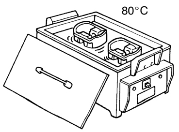
Washing installation - installation for washing large parts weighing up to 500 kg in aqueous solutions of synthetic detergents at temperatures up to 80 degrees. |
|
|
Installation for draining and pumping oil. It is a sealed container on wheels with a pump that creates a vacuum inside the unit, and a set of special probe probes through which the oil flows through a hose into the barrel. |
|
|
Supporting single-lane crane-girder. itspecial equipment used in production and in workshops for loading and unloading goods, as well as for their transportation. |
|
|
A sliding hydraulic lift is a device for raising a car to the required height with technological influences on it. |
|
|
The reciprocating compressor is a device for industrial use for compressing and supplying air and other gases under pressure. |
|
|
Hydraulic press for straightening bending of crankshafts and camshafts. |
|
|
|
Electric heating installation - designed to heat parts to a predetermined temperature in an aqueous medium. |
|
The muffle furnace is designed to heat parts during their repair. |
|
|
The locksmith workbench is a special table on which locksmith work is performed. |
|
|
The rack is designed for stacking ready-made units or requiring repairs. |
|
|
The tool trolley is used to place various types of tools and devices in its compartments. |
|
|
Chest for cleaning materials. |
|
|
Waste bin. |
1.5 Tools and devices.
To perform dismantling and assembly work, use sets of fitter's and assembly tools, as well as pullers and accessories.
The minder's set consists of 135 items for car service:
open-end wrenches 4-11 mm; combined keys 6-34 mm; spanner keys 6-22 mm; starter keys; a set of 3/4 "heads; a set of 1/2" heads; a set of 1/4 "heads; screwdrivers 13 pcs; a set of probes 0.05-1.0 mm; universal pliers of 3 sizes, nippers, pliers, platypuses; hammers 2 pcs., drifts, cores, chisels ratchet with cardan 3/8, extension 3/8, candle keys 20.8 and 16.0 mm.

Rice. 1. Fig. 2 Fig. Fig. 3 4

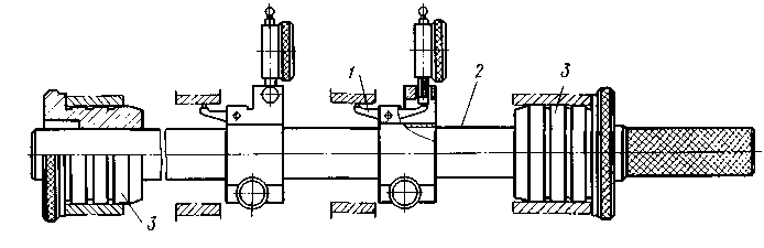
Fig. 5 Fig. 6 Fig. 7
Locksmith vices.
Locksmith's vice (Fig. 1) is a locksmith's tool for fixing parts for various types of processing. A vise is a pair of parallel jaws, one of which is usually stationary, and the other is pressed against the part with a screw.
Pneumatic wrench.
Hand tool (fig. 2), reversible straight, designed for screwing and unscrewing rigid threaded connections.
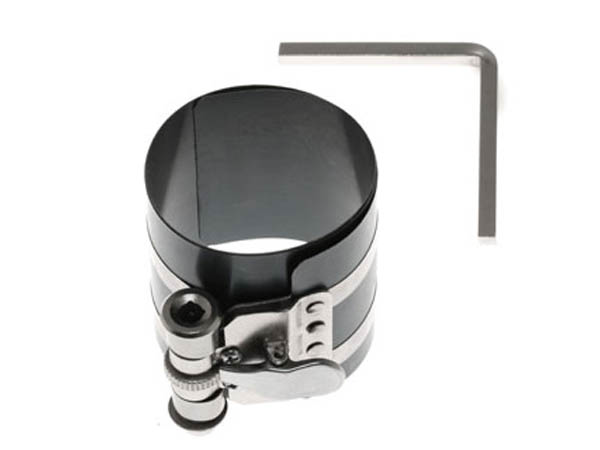
Holder for piston rings.
When assembling the engine, when it is necessary to install the pistons in the cylinders, the piston rings must be compressed. This requires a special mandrel (fig. 3). This mandrel is a steel band with a special key operated clamp.
Piston ring remover.
Allows to dismantle piston rings without risk of damaging them (Fig. 4).
Cylinder liner strippers.
Designed for extrusion of replaceable liners from the cylinder block (Fig. 5).
Connecting rod geometry checker.
Necessary when checking the straightness of the engine connecting rods (fig. 6).
A device for checking the main bearing seats.
The device controls the alignment of the seats of the main bearings of the engine crankshaft (Fig. 7).
1.6 Maintenance of the crank mechanism.
With EO, the engine is cleaned of dirt, its condition is checked visually and the operation is listened to in different modes.
For TO-1, check the fastening of the engine mounts. Check tightness
connections of the cylinder head, oil pan, crankshaft oil seal. If the head is not tightly connected to the block, oil leaks will be visible on the walls of the cylinder block. With a loose connection of the oil pan and the crankshaft oil seal, it is also judged by oil leaks.
With TO-2, it is necessary to tighten the cylinder head fastening nuts. Tightening the head made of aluminum alloy is carried out on a cold engine with a torque wrench or with a conventional wrench without the use of attachments. The force should be in the range of 7.5 - 7.8 kgf / m. The tightening should be done from the center, gradually moving to the edges and at the same time it should go cross to cross, without jerking (evenly). Tighten the oil pan mount.
CO check the condition of the cylinder 2 times a year piston group.
1.7 Diagnosis of malfunctions of the crank - connecting rod
Mechanism.
|
Malfunction |
Cause |
|
The engine will not start |
Weak compression in the cylinders due to wear of the piston group |
|
The engine runs intermittently and does not develop the rated power |
Water entering the cylinders from the cooling system |
|
Piston rings worn |
|
|
Discharge pipe clogged |
|
|
Smoky Exhaust Gas Discharge |
Coking of the piston rings |
|
Piston group wear |
|
|
Engine not warmed up |
|
|
Water ingress into cylinders |
|
|
Engine knocks |
Worn piston pins, holes in the piston bore and upper connecting rod head |
|
Worn pistons and liners |
|
|
Crankshaft liners and journals are worn out |
The state of the piston - piston rings - cylinder liner interface can be estimated by the amount of gases breaking through the crankcase. This diagnostic parameter is measured using a KI-4887-1 flow meter (Fig. 8), after preheating the engine to normal thermal conditions.
The device has a pipe with 6 inlet and outlet valves. The inlet pipe 4 is connected to the oil filler neck of the engine, the ejector 7 for suction of gases is installed inside the exhaust pipe or connected to a vacuum unit. As a result of the vacuum in the ejector, blow-by gases enter the flow meter. Installing with the help of taps 5 and 6 the liquid in the columns of the manometers 2 and 3 at the same level, they achieve that the pressure in the crankcase cavity is equal to atmospheric. The pressure drop m / g is set according to the manometer 1 the same for all measurements using the tap 5. The scale of the device determines the amount of gases breaking through into the crankcase and compares it with the nominal (l / min):
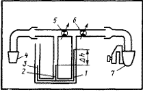
Fig. 8. Diagram of the KI-4887-1 flow meter: 1-3 - manometers, 4 - inlet, 5, 6 - taps, 7 - ejector.
External manifestations of malfunctions of parts of the cylinder-piston group - (pistons, liners and piston rings) are as follows:
Increased oil consumption for topping up;
Deterioration of engine starting qualities;
Decrease in power and economic indicators;
Increased consumption of crankcase gases;
Significant deterioration of the crankcase oil condition.
Diagnosing the state of the CPG parts according to the indicated manifestations is rather difficult, since they can be affected by malfunctions of other components and systems of the engine. For example, along with wear and defects of parts of the CPG, malfunctions of the electrical equipment system (batteries, starter, generator) and adjustment times of the fuel equipment (an increase in the fuel injection advance angle, a decrease in starting feed, a decrease in the performance of the booster pump, etc.) ... Therefore, when diagnosing parts of the CPG, it is necessary to make sure that other units and systems of the engine are in good working order, which affect the performance of the parts in question. So, in cases of increased oil consumption for topping up (above 1.5%), it is necessary to make sure that there is no oil leak from the engine and that there is no leakage in the intake tract.
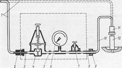
Fig. 9 Device model K-69M for determining the technical condition
cylinder-piston group of the engine;
1 - hose from the compressed air line, 2, 11 - quick-release couplings, 3 and 8 - fittings, 4 - reducer, 5 - calibrated hole, b - pressure gauge, 7 - adjusting screw, 9 - union nut, 10 - hose for connecting the device to the engine, 12 - a fitting screwed into the hole for the injector.
The operation of the device is based on measuring the leakage of air supplied under pressure into the cylinder of an idle engine through the injector hole.
The device consists of a reducer, a pressure gauge with a scale calibrated as a percentage of air leakage, an adjusting screw, inlet and outlet fittings, a hose for connecting the device to the engine cylinder, quick-release couplings for connecting the compressed air hose to the device and a fitting screwed into the threaded hole for the nozzle ... An audible warning device is supplied with the device to determine the end of the compression stroke in the engine cylinder before starting the test. To determine the beginning and end of the compression stroke in diesel engines, a probe indicator is used. If the value of the air leakage at the piston position in v. m.t. more than the limit, you should check the air leakage through the valves with a stethoscope and make sure there is no air leakage through the engine cylinder head gasket. If, when wetting the cylinder head gasket with soapy water, air bubbles appear on it or in the filler neck of the radiator, this indicates a weak tightening of the cylinder head nuts or the beginning of the destruction of the gasket. There may be a crack in the cylinder block or combustion chamber.
Engine knocks are listened to with a stethoscope, by touching the end of the rod or to the listening areas on the engine.
The condition of the crankshaft main bearings is determined by listening to the bottom of the cylinder block with a sharp increase and decrease in engine speed. Worn main bearings emit a strong, low-pitched thud, which intensifies with a sharp increase in the crankshaft speed.
The condition of the crankshaft connecting rod bearings is determined in the same way. Worn connecting rod bearings emit a mid-tone knock, similar in nature to the knock of main bearings, but less strong and more sonorous, disappearing when the nozzle of the cylinder being listened to is turned off.
The work of pairing the piston - the cylinder liner is listening
over the entire height of the cylinder at low crankshaft speed with a transition to medium. The appearance of a sound that resembles
the fluttering sound of a bell that increases with engine load and decreases as the engine warms up,
indicates a possible increase in the clearance between the piston and the cylinder liner, a bend in the connecting rod, a misalignment of the axis of the connecting rod journal or
piston pin, especially if the engine has increased consumption fuel and oil. Squeaks and rustles in the piston-cylinder liner interface indicate an incipient jamming in this interface, caused by a small clearance or insufficient lubrication.
The state of mating the piston pin - the bushing of the upper connecting rod head is checked by listening to the upper part of the cylinder block at a low crankshaft speed with a sharp transition to the middle one. A sharp metallic knock, reminiscent of frequent hammering on the anvil and disappearing when the injectors are turned off, indicates an increase in the gap between the piston pin and the bushing, insufficient lubrication or an excessively large advance in the start of fuel delivery.
Mating the piston ring - the piston groove is checked at level n. m. t. piston stroke at an average crankshaft speed. A faint, high-pitched clicking knock, similar to the sound of the rings hitting one against the other, indicates an increased gap between the rings and the piston groove, or a fracture of the rings.
Engine power and economy depend on the compression in the cylinders. Compression decreases with significant wear or breakage of parts of the cylinder-piston group. Compression is evaluated by the pressure in the combustion chambers of the engine during the compression stroke and measured with a compression meter.
To check the compression in the cylinders with a compressor, the engine is heated to a coolant temperature of 80-90 ° C, after which it is stopped.
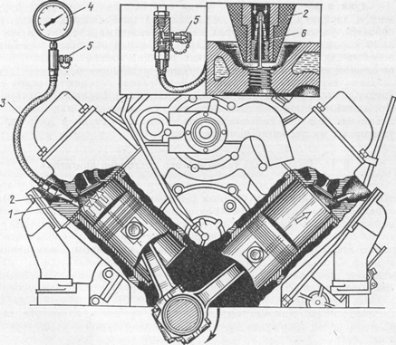
Fig. 10 Compression test with a compressor:
1 - cylinder head, 2 - rubber tip, 3 - hose, 4 - pressure gauge, 5 - air release valve, 6 - spool
The measurement of the compression of the diesel engine is carried out with the cut-off lever pushed down and the de-energized solenoid valve, which is responsible for cutting off the fuel supply, which is located on the highway.
The compressor is connected to the injector port. Rotate the crankshaft of the engine with a starter 10 - 12 revolutions. The pressure in the cylinder is read off the manometer scale. It should be remembered that for this they use a device designed to measure the compression of a diesel engine with a measurement limit of at least 60 atmospheres. In good condition, the compression of the diesel engine (the value obtained as a result of measurements) should be within 30 kg / cm2.
To determine the wear of the liners, measurements are performed with an internal gauge in two mutually perpendicular directions and in three belts. One direction is set parallel to the crankshaft axis. The first belt is located at a distance of 5-10 mm from the upper plane of the block, the second - in the middle of the sleeve, and the third - at a distance of 15-20 mm from the lower edge of the sleeve. Measurements are made with an indicator bore gauge.
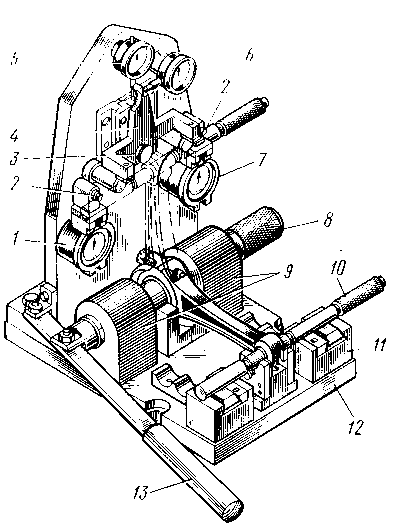
The main bearing seats are checked with a rolling pin for deformation. If the rolling pin enters the slots and turns without great effort, then there is no deformation, wear, as well as deviation from the alignment of the main bearing slots can be installed with a special device (Fig. 12). The principle of its operation lies in the fact that the rolling pin 2 with the help of bushings 3 is fixed in the sockets of the main bearing shells. On the rolling pin, indicators are placed (sequentially when entering the sockets) to control each hole. Levers 7 of indicator devices are inserted into the measured hole. The indicators are set to zero and fixed to a rolling pin. As the rolling pin rotates, the deflection of the indicator arrows will show twice the deviation from the alignment of each hole.
Fig. 12 Tool for checking the main bearing seats:
1 — lever, 2 — rolling pin, 3 — bushings.
Various devices are used to straighten and control connecting rods. On the device shown in Fig. 13, simultaneously check the bending and twisting of the connecting rod, as well as the distance between the centers of its heads. If deviations are found that exceed the permissible values, the connecting rod is ruled with a special key without removing it from the device. In this case, the upper head of the connecting rod should occupy a position between the vertical and horizontal plates. The connecting rod is tightly installed in the device using a large rolling pin 8 passed through the struts 9. The small rolling pin 10 is inserted into the machined hole of the upper connecting rod head. First, pre-check the torsion of the connecting rod. For this, the connecting rod, installed in a horizontal position, is manually turned so that the small rolling pin 10 alternately rests on the cracks of the struts 11. The presence of a gap indicates the presence of twisting of the connecting rod. Determination of the amount of twisting and bending is carried out when the connecting rod is in an upright position. In this case, the small rolling pin 10, in contact with the stops of the rocker arm 4, is in contact with the pins 2 of the indicators 6 and 7, which indicate the twist of the connecting rod.
Indicator 5 sets the deviation of the distance between the axes of the holes
upper and lower heads, and indicator 6 - non-parallelism of the axes of the holes.
After straightening and control, sharply moving the handle 13, knock out a large rolling pin 8, freeing the connecting rod. Before starting work, the indicators of the device are adjusted to the reference connecting rod.
Rice. 13 Tool for checking and straightening the connecting rod:
1, 5, 6, 7 — indicators, 2 — pins, 3 — axis of the rocker arm, 4 — rocker arm. 8, 10 — large and small rolling pins, 9, 11 — racks, 12 — plate, 13 — handle.
1.8 Repair of the crank mechanism.
The main defects of the crankshaft are: bending, wear of the connecting rod and main journals, wear of the bearing bore of the gearbox drive shaft and the holes in the cash flange for the flywheel mounting bolts, Wear of the keyways for the gears and the pulley. They are deposited with subsequent machining, neck diameter grinding and groove milling. The ratchet threads are driven by a tap.
The bending of the engine crankshaft is checked on a bench, on prisms mounted on a control plate or in the centers of a lathe using an indicator. Bending (beating of the middle root journal relative to the extreme ones) in excess of the permissible technical conditions is eliminated by straightening on the press. Crankshaft set on the prisms with extreme root journals, and with the press rod through a copper or brass gasket, press on the middle washer from the side opposite to the bend. In this case, the deflection should be approximately 10 times greater than the bend to be eliminated. The shaft is kept under load on the press for 2-4 minutes. After straightening, it is recommended to subject the shaft to heat treatment, that is, to heat it up to 180-200 ° C and hold it at this temperature for 5-6 hours. Then the shaft is checked for beating. The runout of the middle necks in relation to the extreme necks should not exceed 0.05 mm.
The worn out connecting rod and main journals of the crankshaft are restored by grinding to the repair size. One repair dimension is set for all connecting rod journals and one repair dimension for the main journals, depending on the smallest diameter obtained as a result of measurement and the repair size recommended by the technical conditions. The processing of the shaft journals is completed by polishing or superfinishing until the required surface roughness is obtained. Polishing is carried out on polishing machines with a polishing paste or polishing tape. Then the oil channels and the outer surface of the shaft are washed with kerosene in a special bath. When all repair dimensions have been used and a further reduction in the shaft diameter is unacceptable, but its strength is sufficient, the journals can be restored by surfacing followed by processing to the nominal size. If cracks are detected, the shaft is rejected.
The main defects of the flywheel are: cracks in the contact plane of the clutch disc to the flywheel (rejected); wear of the contact plane in the aisles permissible for repair (eliminated by grinding, over the permissible - rejected); wear of the gear rim - the rim is repressed; a worn hole in the shaft flange for the flywheel mounting bolts is processed with a reamer to a repair size assembled with a flywheel. When assembling, the flywheel mounting bolts of an oversized repair size are installed.
The bearings of the connecting rod and main journals of the crankshaft are made in the form of thin-walled steel liners, filled with antifriction alloy on the inside. Plants produce liners of both nominal and repair sizes. When they are worn out, the liners are replaced without any additional adjustment. The inserts are replaced in pairs only.
Cylinder block defects are established by careful inspection, cylinder measurement and pressure testing. Inspection establish holes, chips, cracks visible to the eye, thread breaks and determine the state of the cylinder mirror. By pressing on the stand, cracks are found that were not detected during inspection. Water is injected into the block cooling jacket under a pressure of 0.4-0.5 MPa. In this case, a block head must be installed on the cylinder block or a cast iron plate with a rubber gasket must be installed instead. Turning the frame of the stand, inspect the unit and establish whether there is a water leak. In the presence of cracks passing through the cylinder mirror, valve seats and the plane of the connector, the cylinder block is rejected. Before welding the crack, its ends are drilled with a drill with a diameter of 5 mm and cut along the entire length with a grinding wheel at an angle of 90 ° to a depth of 4/5 of the wall thickness. The crack is welded with argon-arc welding, while the seam should be even, continuous and protrude no more than 1.0-1.5 mm above the base metal. The weld is cleaned flush with the plane of the base metal with a file or emery wheel. Then the cylinder block is subjected to pressure testing on the bench, checking the tightness of the weld. Water leakage through the seam is not allowed. Cracks and holes in the cylinder block can be repaired with epoxy pastes. The surface of the block on both sides of the crack is cleaned to a shine with a metal brush or stone chips on an installation for cleaning parts. At the ends of the crack, holes are drilled with a drill with a diameter of 3-4 mm, a thread is cut into them and plugs made of copper or aluminum wire are screwed in flush.
The crack is processed at an angle of 60-90 ° with a chisel or an abrasive wheel to a depth of 3/4 of the wall thickness. On the surface of the block around the crack at a distance of up to 30 mm, roughness is created by notching with a chisel or shot blasting. Degrease the prepared block surface with acetone or gasoline. With a spatula, layers of epoxy paste are successively applied to the prepared dry surface. First, a layer of paste up to 1 mm thick is applied, sharply moving the spatula on the surface of the block. Then apply a second layer of paste with a thickness of at least 2 mm, rubbing it thoroughly.
The total thickness of the paste layer on the entire surface should be 3-4 mm.
After sealing the crack, the cylinder block is kept for 25-28 hours until the paste has completely hardened. The paste hardening process can be accelerated by heating a muffle furnace to 100 ° C or by evaporating the hardener (polyethylene polyamine) at a temperature of 105-110 ° C, followed by holding at this temperature for 3 hours. The repaired surface is cleaned with a file or an abrasive wheel. The streaks of the paste are chopped off with a chisel. External holes that can be repaired are repaired with patches. First, the edges and surfaces around the holes are cleaned and degreased. Then the paste is applied and a 0.3 mm thick fiberglass patch is applied and rolled on with a roller.
The distance from the edge of the patch to the edge of the hole should be at least 15–20 mm. After that, a second layer of paste is applied and a second patch is applied so that it overlaps the first by 10-15 mm on all sides. The patch is rolled up. In this sequence, eight layers of fiberglass are applied. The last layer of the patch is covered with a paste to protect it from damage. After repairing the hole with patches and mechanical treatment of the applied layer of paste, the cylinder block is subjected to pressure testing on a bench. If no water infiltration is detected within 5-6 minutes, then the repair of the unit is done with high quality. Block cracks in the cooling jacket can be repaired by placing pins. First, holes are drilled at the ends of the crack with a drill with a diameter of 4-5 mm. Then, with the same drill, holes are drilled along the entire length of the crack at a distance of 7-8 mm from one another. The threads are cut and the copper rods are screwed in to a depth equal to the thickness of the block wall. The rods are cut with a hacksaw, leaving the ends protruding 1.5-2.0 mm above the surface of the part. Drill the holes between the installed pins so that they overlap them by "/ 4 of the diameter. Cut a thread, screw in copper rods and cut them with a hacksaw, leaving the corresponding ends. Then, with light hammer blows, the ends of the pins are punched out, forming a tight seam. If necessary, then the seam leveled with a file, then the cylinder block is pressed.
A cylinder block that has chips that are acceptable for repair is restored by surfacing or welding a patch.
Boring is the main method for restoring liners. The cylinder is bored to the piston size, taking into account the required thermal clearance and the honing allowance (0.06-0.08 mm). After boring, the sleeve is honed. During machining, the honing head, connected to the spindle of the machine, is inserted into the hole to be machined (the bars are in a compressed state). Initially, preliminary honing and then final honing are carried out. A honing head with a mechanical, hydraulic or pneumatic expanding device is used.
The pneumatic drive ensures constant pressure of the stones on the cylinder wall, which improves the quality of processing and the productivity of the honing process. In this case, it is possible to regulate the pressure of the bars on the surface to be treated and to automate the process of unclenching the bars as the diameter of the sleeve changes. To obtain the correct geometric shape of the cylinder during the honing process, it is necessary to set a certain stroke length of the head. It should be such that the abrasive bars extend beyond the end of the cylinder to a distance not exceeding 0.2-0.4 of their length. With a longer stroke of the honing head, shape errors, in particular concavity, are observed, and with a smaller stroke, barrel shape is observed.
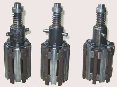
Fig. 14 Honing heads.
Honing is carried out with continuous and abundant supply of cutting fluid to the processing zone. Kerosene or a mixture of kerosene and spindle oil is used as a cutting fluid.
Honing is carried out in three stages: rough honing, finishing
honing (in both cases with ceramic stones) and brushes made of nylon fibers reinforced with silicon carbide. When honing, be sure to check the cylinder size. For preliminary honing, bars of AlOMxSO synthetic diamonds are recommended, and for final honing - BX-100x11x9K38BS. Processing is carried out in the following modes: the circumferential frequency of rotation of the head - 280 min-1, and the speed of the reciprocating movement - 90 double strokes per minute. The allowance for preliminary honing is set to no more than 0.08 mm; final - 0.04 mm. The final processing of engine cylinders can be carried out with ball rolling heads, which allows obtaining a surface of the required accuracy and a given roughness.
The process is carried out after boring or simultaneously, in one pass, the cylinder bore is machined with a cutter and a head ball.
Worn and deformed main bearing seats are bored to nominal size. The removed bearing caps must be marked (put the cylinder block number and the serial number of the cap). The joint planes of the cover are milled to a certain size (0.6-0.8 mm) and controlled with an indicator device. Mill the outer groove in the front cover, and the shaped groove in the rear main bearing cover. The finished and OTK approved covers are assembled with the cylinder block in accordance with their marking. The assembled cylinder block with covers is installed and fixed on the plate of the boring machine. The main bearing holes are bored in one working stroke with cutters mounted on the boring bar to the size established by the drawing or technical specifications. After boring, check the hole dimensions, surface roughness and center-to-center distance between the main bearing bores and the camshaft bushings.
The main piston defects are carbon deposits on the bottom and grooves, wear of the ring grooves, holes in the bosses, cracks and scratches on the walls. To clean the piston grooves from carbon deposits, use a device in the form
steel tape with handles, on the inner surface of which cutters are fixed. By inserting the cutters into the groove and turning the tool around the piston, carbon deposits are removed. Pistons with worn piston ring grooves are replaced with new ones of appropriate sizes. A worn hole in the piston bosses is restored by deployment followed by installation of an oversized piston pin. Minor scratches or scratches on the outer surface of the piston can be removed by sanding. Pistons with cracks and deep scratches are replaced with new ones.
Worn out piston rings that have lost their elasticity are replaced with new ones. The selection of new rings is made in accordance with the dimensions of the piston and cylinder. When the ring is selected to the piston, it is rolled along the groove, and if there is no jamming, then the gap is determined with a feeler gauge. If the ring is jammed in the groove or there is a small gap, the ring is ground on a sheet of fine-grained emery paper placed on a surface plate. The clearance along the groove height should not exceed 0.052-0.082 mm for the top and 0.035-0.70 mm for the rest of the compression rings. When fitting along the cylinder, the gap is determined at the joint of the ring installed in the cylinder. The ring can be installed in a caliber, the inner diameter of which is equal to the diameter of the cylinder. In the absence or a small gap, the joints of the rings are filed with a personal file. In this case, the planes of the joints of the rings should be parallel. For compression rings, the gap should be 0.3-0.5 mm, and for oil scraper rings- 0.15-0.45 mm. If the gap is larger than normal, the rings are rejected.
Worn piston pins are restored with chrome plating. A build-up of porous chromium is carried out, which retains the oil well. After applying a layer of chromium, the fingers are ground to the required size.
When worn over a diameter of more than 0.03 mm, the fingers are repaired or replaced with new ones. It is recommended to install piston pins only of the nominal size when overhauling the engine. For ease of assembly, their sizes are sorted into a number of groups.
The main defects of the connecting rod are bending and twisting of the rod, wear of the bore of the upper head bushing and bore holes, wear of the bore and end surfaces of the lower head. The worn out bushings of the upper connecting rod head are replaced with new ones. Sometimes the bushing hole is bored or reamed to fit the larger oversize of the piston pin. The holes of the lower head of the connecting rod for the liner are bored and grinded to the nominal size after processing the butt surfaces of the cap with the connecting rod. The latter are milled or ground using special tools. If there is a galvanized section, it is advisable to repair the hole of the lower connecting rod head by letting it rest. After letting go, the hole is restored to its nominal size. Bending and twisting of the connecting rod is eliminated by straightening.
The main defects of the block head are:
warping of the working planes of the head: within the permissible range, eliminated by grinding the planes, above the permissible level - the heads are rejected;
stripping of threads and creases of bolts and studs (stripped threads are restored by setting screwdrivers); creases of bolts and studs are turned out or drilled out, cracks in irrelevant places are welded with argon-arc welding).
2. Safety rules when carrying out maintenance,
Diagnostics and repair of road transport.
Maintenance and repair of the car must be carried out in a special room with the use of fixtures, devices, equipment, as well as fitting and assembly tools, which are designed for a specific type of activity.
The car, which is installed at the place of technical inspection or repair, must be put on the parking brake, and also securely fixed with the help of two stops that are placed under the wheels. In this case, the gearshift lever must be set to a position that corresponds to lowest gear... When setting on vehicles with carburetor engine or with a gas distribution system, the ignition must be turned off, and on cars with diesel engine you need to shut off the fuel supply. In addition, on wheel put up a sign: “Do not start the engine: people are working!”.
If the car is serviced using a mechanical lift, then a sign should be attached to the control mechanism: “Do not touch, people are working! The thrust legs of the lift must be rigidly fixed in the working position with a metal stop that would prevent the car from spontaneously lowering on the lift. Inspection ditches must be kept clean andsafety guiding sides - flanges. The bottom and walls of the inspection ditch should be free of dampness and traces of spilled engine oil. When working with high-lying parts, it is necessary to use metal supports, which must be strong, reliable and stable. Maintenance and technical repair must be carried out with the engine off, except for those cases when the engine operation is necessary for the implementation of the technical process of this operation.
Starting the engine and moving the car from a place is carried out taking into account the safety of people working near the car.
Trial brake system the car must be produced at a special stand. In addition, such a test is allowed to be carried out on a special site if its dimensions allow for the safety of people and the car in the event of a brake system malfunction.
When carrying out adjustment work with the engine running, the service station room must be equipped with a suction to remove exhaust gases from the room.
2.1 Types of instruction.
Introductory briefing - is carried out with all those who are hired, regardless of work experience and type of work, as well as with students and students who came to work for practical training. The main instructors on labor protection instruct on this briefing. The briefing can be conducted with one or a group of people.
Initial briefing is carried out with an employee when transferring from one type of work to another. Each employee is instructed separately.
Re-instruction is carried out once every 3 months, regardless of classification, length of service and type of work. The purpose of the exercise is to check and increase the level of knowledge of the rules and regulations.
Unscheduled briefing is carried out in the same way as the initial briefing due to changes in labor protection rules, the technical process of raw materials, replacement or normalization of equipment, as well as if the employee violates labor protection requirements. It is carried out both with one and with a group of people of the same profession.
Current briefing is carried out immediately before starting work. Workers and engineering and technical workers engaged in work of increased danger are allowed to perform official duties only after completing coursework and passing exams, as well as obtaining a certificate for the right to work and service this enterprise mechanisms. Training is carried out at least once every 2 years.
2.2 Safety rules when using the tool and
Adaptations.
Fitting and assembly tools used at maintenance and repair posts must be clean and serviceable. It is necessary that hand tools (hammers, chisels, etc.) have no damage (gouges, chips) of working edges, burrs, scoring and sharp edges. The back of the percussion instruments should be smooth.
Hammers and sledgehammers should be securely mounted on wooden handles and wedged with barbed metal wedges. The surface of the tool handles must be smooth and free from burrs or cracks.
It is not allowed to use keys with worn edges and inappropriate sizes, the use of levers to increase the shoulder of wrenches.
When inspecting vehicles, it is allowed to use only portable safety lamps with a voltage of 36 V, which are equipped with safety nets. When inspecting in the inspection ditch, it is necessary to use lamps with a voltage not exceeding 12 V. Hand-held power tools may only be connected through sockets with a grounding contact. Power tool leads must not touch the floor and must be suspended.
Car maintenance is performed on production lines or posts equipped with an inspection ditch, lift or overpass.
When placing the car at a maintenance or repair station, it is necessary to hang a sign on the steering wheel with the inscription: "Do not start the engine - people are working!" If forced movement from one post to another is not provided, the car must be braked with the parking brake and the first gear in the gearbox must be turned on, the ignition must be turned off, and at least two stops (shoes) must be placed under the wheels.
When the vehicles are forcibly moved from post to post, to warn those working on the production line, light or sound alarms are arranged at each post. The operator starts the conveyor only after receiving signals from all posts on the control panel about the performance of the set amount of work by the workers. When a signal is given to start the movement of the conveyor, workers are required to leave their workplaces, get out of the inspection ditch and move away from the conveyor. For an emergency stop of the conveyor, the Stop buttons are mounted at each post.
When servicing a car installed on a lift, it is necessary to attach a plate with the inscription "Do not touch - they work under the car" on the lift control mechanism.
In order to avoid spontaneous lowering of the hydraulic lift after lifting the vehicle, securely fix the position of the plunger with a stop (rod).
When servicing and repairing a car with removed wheels, hung out on jacks, hoists and cranes, it is allowed to start work only after the car is installed on supports (tragus), while stops must be placed under the wheels that have not been removed. The stands must be made of metal, sturdy and reliable.
When disassembling a car, remove, transport and install the engine, gearbox, rear axle, front axle, the body and the frame should be carried by lifting and transport mechanisms equipped with grippers, which guarantee complete safety of work. The vehicle must not be lifted or suspended by the towing hooks. When lifting and transporting units, do not stand under the raised parts of the vehicle.
Transport trolleys must have stands and stops that protect the units from falling and spontaneous movement on the trolley. The supporting surface of the jack heads must have a shape that excludes slipping of the lifted load (vehicle, unit).
Stands for dismantling and assembly works during the repair of units must correspond to their purpose and be convenient. Devices for securing units must exclude the possibility of displacement or fall of the latter. To carry out adjustment work with the engine running, a special post must be allocated in the maintenance area, equipped with a local suction to remove exhaust gases.
Portable light bulbs must have a voltage of no higher than 36 V, and in especially hazardous areas - 12 V. Power tools operate at a voltage of no higher than 220 V. In rooms without increased danger and not higher than 36 V. In rooms of increased danger and outdoors. The body of the power tool (at voltages above 36 V) must be grounded. Before using power tools, make sure that the grounding and insulation of the wires are in good condition, that the cable is securely attached to the case, and that there are no exposed live parts. It is recommended to suspend the cables, keeping them away from wet and oily surfaces. When working with a portable power tool with a voltage of more than 127 V, it is imperative to use dielectric gloves, rugs, galoshes, stands. At a motor transport company, an employee must be allocated who is obliged to monitor the health of the power tool and portable lamps.
If the power supply is interrupted while working with the power tool or interruptions in work, the power tool must be disconnected from the mains.
Persons using a power tool are prohibited from:
- transfer the power tool, at least for a short time, to other workshops and to unauthorized persons;
- disassemble the power tool and carry out any repairs yourself (both the power tool itself and the connection wires, etc.);
- hold on to the power tool cord or touch a rotating, cutting tool;
- remove chips with your hands while operating the power tool;
work at a height of more than 2.5 meters from ladders.
When using a power tool or portable electric lamps, their wires and cables should be suspended whenever possible, and do not allow direct contact of wires and cables with metal, hot and oily surfaces.
Conclusion.
In this course work, the planned preventive system of maintenance and repair of the rolling stock of road transport is considered. Its forms and methods of diagnostics, maintenance and repair of cars.
A description of the motor section is given, a control and measuring instrument, diagnostic, technological equipment and organizational equipment are selected. The maintenance and repair methods of the crank mechanism of the KamAZ 740 engine are described.
Instrumental diagnostic methods are the most objective methods, because when diagnosing, measuring instruments are used that allow to quantitatively measure diagnostic parameters, and by their values to assess the technical condition of the engine. The external manifestations of malfunctions of the CPG parts were also studied and it was concluded that diagnosing the state of the CPG parts by the indicated manifestations is rather difficult, since they can be affected by malfunctions of other components and systems of the engine. For example, along with wear and defects of parts of the CPG, malfunctions of the electrical equipment system (batteries, starter, generator) and adjustment times of the fuel equipment (an increase in the fuel injection advance angle, a decrease in starting feed, a decrease in the performance of the booster pump, etc.) ... Therefore, when diagnosing parts of the CPG, it is necessary to make sure that other units and systems of the engine are in good working order, which affect the performance of the parts in question.
In the second section term paper describes the forms of instruction, safety rules for diagnosis, maintenance and repair of cars. All safety requirements should be observed when servicing the rolling stock of road transport.
Annex 1
Technological equipment and organizational equipment used
During maintenance and repair of the engine.
|
Name |
Model |
Number |
The size |
|||
|
Washing plant |
MPP-1000 |
3500/1250 |
||||
|
Sliding hydraulic lift |
PP 20 |
3000/1 10 0 mobile |
||||
|
Piston compressor |
FIAC AB 500/981 |
1260 / 640 |
||||
|
Locksmith workbench |
VTS-214 |
870/1600 |
||||
|
Tool trolley |
TZI |
830/680 |
||||
|
Installation for draining and pumping oil |
3730 |
Mobile |
||||
|
Hydraulic press |
CP150 |
210 0/ 85 0 |
||||
|
Disassembly stand - engine assemblies |
R-776-01 |
2250 / 1500 |
||||
|
Engine cylinder boring machine |
COMEC AC 200 |
1200/1170 |
||||
|
Supporting single-lane crane |
Mobile |
|||||
|
Horizontal boring machine |
AMC-SCHOU |
2500/1080 |
||||
|
Muffle furnace |
PM 150-01 |
1500/800 |
||||
|
Vertical milling machine |
MMT-50F |
1150/1000 |
||||
|
Electric heating installation |
Tabletop |
|||||
|
Rack |
SGU-50 |
1500/500 |
||||
|
Chest for cleaning materials |
2249-P |
500/1000 |
||||
|
Waste bin |
2217-P |
500/500 |
||||
Appendix 2
Routing.
Assembling the connecting rod-piston group of the eighth cylinder of the engine.
|
P / p No. |
Name and content of works |
Devices, tools, fixtures, model, type. |
Technical requirements. |
|
Select a piston of the required diameter or leave the old piston if it is suitable. |
A set of probes; micrometer |
Measure the diameter of the piston skirt at a height of 10 mm from its bottom edge. The clearance between the piston and the liner must be within 0.025-0.045mm |
|
|
Pick up the piston pin on the connecting rod. |
A set of probes; micrometer |
Finger smeared engine oil, should smoothly enter the upper head of the connecting rod from the effort of the thumb. |
|
|
Insert the circlip into one of the grooves of the piston pin bosses |
Round nose pliers 7814-0114 1/96 |
||
|
Heat the piston and insert a finger greased with engine oil into the boss. |
Electric heating installation RE-7543. Finger installer |
Immerse the plunger in the bath for 2-3 minutes. Water temperature 60-70 C. Use oil M12G1; M8G1 |
|
|
Install the second circlip in the boss. |
Round nose pliers 7814-0114 1/96 |
Be careful as the ring is springy. |
|
|
Install the assembled piston with connecting rod in a vice and secure. |
Vice 7827-0262 |
Be careful when placing the connecting rod in a vice |
|
|
Choose a piston ring according to thermal gap in the lock of the ring inserted into the cylinder. |
Set of flat probes |
The gap in the lock should be 0.2-0.4mm. |
|
|
Check the free movement of the rings in the piston grooves. |
Set of flat probes |
Check by rolling the ring in the piston grooves by measuring the gap between the ring and the groove wall. The gap should be: for the top ring: 0.02-0.07; bottom: 0.02-0.07; oil scraper: 0.02 - 0.06 |
|
|
Install the piston rings onto the piston. |
Tool for removing and installing piston rings. |
Be careful not to break the rings. |
|
|
Remove the assembled unit from the vice. |
|||
|
Repeat steps 1-10 for the remaining pistons. |
|||
|
Lubricate piston rings and piston skirt with oil. |
Brush; oil container |
Use oil М12Г1; М8Г1 |
|
|
Expand the piston rings, spreading the locks in the piston grooves. |
Ring template |
The locks of adjacent rings should be 120 degrees apart from each other. |
|
|
Crimp the rings with a tool and install the subassembly into the cylinder. |
Piston ring adapter 9480-2379 |
Be careful, damage to parts is not allowed. |
Bibliography.
1.Bednarsky V.V. Series: "Secondary vocational education" - Rostov n / a: "Phoenix", 2010.- 464 p.
2. Vlasov VM, Zhankaziev SV, Kruglov SM, and others; Maintenance and repair of cars: a textbook for students. institutions of environments. prof. education. Ed. V.M. Vlasov. - 2nd ed., P. - M .: Publishing Center "Academy", 2010.- 480s.
3. Grafkina M.V. Labor protection and fundamentals of environmental safety
Automobile transport: textbook. - M .: Publishing Center "Academy", 2009-192s.
4.Epifanov L.I., Epifanova E.A. Maintenance and repair of cars: a tutorial. - 2nd ed. Rework. and add. - M .: Publishing House "Forum": Infra - M, 2010. - 352 p.
5. Klanitsa, V.S. Labor protection in road transport: Educational
manual for the beginning. prof. education / V.S. Klanitsa. - M .: ITs Academy,
2012 .-- 176 p.
6. POT R0-200-01-95 "Rules for labor protection in the automobile
year number 28
7.Turevsky I.S. Car maintenance.
Book 2. Organization of storage, maintenance and repair of road transport: a tutorial. - M .: Publishing House "Forum". INFRA - M, 2011. - 256s.
8.Turevsky, I.S. Labor protection in road transport: Educational
manual / I.S. Turevsky. - M .: ID FORUM, INFRA-M, 2010 .-- 240 p.
Introduction
In the Russian Federation, a planned preventive system for the maintenance and repair of cars, construction and road machines has been adopted. The main provisions are formulated and enshrined in the "Regulations on the maintenance and repair of the rolling stock of road transport". This Regulation shows the liver of the provided types of maintenance and repairs and operations for them, the standards for overhaul runs, labor intensity for performing various types of work, standards of downtime in maintenance and repair, correction factors for various standards (K1-K5), depending on the specific operating conditions ...
The essence of the planned preventive system is the compulsory delivery of cars and machines that have passed the standard mileage, according to the plan, to the appropriate type of maintenance in order to prevent increased wear intensity and restore the lost performance of components, assemblies and systems.
The regulation provides for:
1) Daily maintenance - EO
2) Maintenance No. 1- TO-1
3) Maintenance No. 2 - TO-2
4) Seasonal service - CO.
5) Current repairs - TR.
6) Overhaul - CD.
These types of services differ from each other in the list and the complexity of the operations performed and, of course, in the frequency.
EO -control inspections of units, mechanisms and systems. Cleaning and washing operations and refueling operations - adding oil, fluids for components and systems and mechanisms.
TO-1 - to maintain equipment in good condition, identify and prevent failures and malfunctions, work is carried out: diagnostic. fastening and adjusting, lubricating, cleaning. electrical.
TO-2-oil change or repair of parts and assemblies, except for the main ones. The term is up to one day, without the right to access the line, in accordance with the Operational Regulations.
CO - is carried out twice a year, in spring and autumn, designed to prepare transport for operation, taking into account climatic conditions, usually combined with TO-2 . At the same time, increasing the standard labor intensity for additional operations, and a more thorough check of various units with forced removal from the car and machines for testing at stands and control devices.
TR - carried out on demand with lower cost standards, in equipped special areas: on lifts, inspection ditches.
KR - cars and assemblies are carried out at specialized repair enterprises or bases, with complete disassembly into separate assemblies and assemblies to parts. After washing and cleaning, troubleshooting and sorting are carried out, followed by replacement with serviceable or new parts. After completing, assembly, testing, and running-in are performed. Final assembly takes place on the main conveyor or workshop. An indispensable condition for the KR is the standard mileage: for passenger GAZ - 300 thousand km, for freight - 250 thousand km for a new generation of trucks - 300 thousand km.
The costs of maintaining cars and machines in a technically sound condition with ensuring high operational reliability, assigned to the repair services of various ATPs, are several times higher than the costs of manufacturing new cars. Therefore, an important direction to increase the productivity of repair workers, while improving the quality of work and the efficiency of the entire production. The introduction of the latest technologies using modern high-performance equipment, complex mechanization and automation of maintenance and repair processes for cars and machines.
1 . Generalpart
Repair depends on the degree of wear or damage to the machine or unit. Repair - a set of technological operations on a machine or unit in order to restore its operational properties to standard requirements.
There are several types of repairs:
Current repair - restoration of one or some group of its operational properties to the standard level.
Scheduled repair - a set of technological influences on a product, carried out depending on the established by the manufacturer's regulations, planned operating time in order to restore one or some group of its operational properties to the standard level.
Emergency current repair - a set of technological influences on the product, carried out in order to eliminate or prevent accidental failure.
Overhaul is a set of technological impacts on a product, carried out in order to restore all its operational properties, including the resource, to the standard level.
Repair methods determine the organizational forms of predominantly assembly processes when restoring a machine. These methods are divided according to several criteria.
On the basis of the preservation of the belonging of the repaired parts to a machine or unit, repairs can be made by impersonal and non-impersonal methods. With the impersonal method, the belonging of the constituent parts or units is not preserved, and with the non-impersonal method, it is preserved.
According to the organization of the execution, the repair of machines can be carried out by the aggregate method (depersonalized repair). Units are replaced with new ones or pre-repaired.
The aggregate method of repair requires a revolving fund, depends on the power of the ARP, the time spent on the exchange, and the safety stock of the units.
With an unpersonalized repair method, faulty units and parts are removed from the machine, repaired and installed on the same machine. The method is used only for machines of exceptional value or available in small quantities.
The flow method is characterized by the location of technical equipment in the sequence of operations of the technological process and the specialization of workplaces. The in-line method provides high productivity, efficient use of equipment and achieves high quality indicators called industrial. It is used at most ATP enterprises.
For the organization of the repair of machines, the following methods are also used:
1) The method of specialized posts.
2) The method of universal posts.
1.1 Descriptioncarandroadmachines, workingonplot
The EO-3323A single-bucket excavator is a multi-purpose earthmoving machine designed for excavation of pits, trenches, quarries in soils of 1-4 categories, loading and unloading bulk materials. Loose rocks and frozen soils, as well as for other work in industrial, urban, rural, transport and land reclamation construction. The main working equipment: a backhoe with a bucket with a capacity of 0.65 m3. Replaceable types of working equipment: digging grab, hydraulic hammer, hydraulic shears, concrete breaker, ripper.
Weight 12.4 tons, bucket capacity (SAE) m3 - 0. 65. Engine D-243 (D-75P1), horsepower. with. 81 (75). Travel speed km. h -20 (17).
The appearance and structure of the excavator is shown in Figure 1
Figure 1 - appearance and structure of the EO-3323A excavator.
1- pneumatic wheel travel,
2- power plant
4- handle
5- hydraulic cylinders (a- booms, b- handles, v- buckets)
7-way bogie
8- transmission
9- support - turntable
10- counterweight
The EO-3323A hydraulic excavator has constructive, technical, and economic advantages due to the use of a hydraulic volumetric drive to transfer power from the engine to working mechanisms, or rather, to implement large gear ratios from the leading link of the energy source to the working mechanisms and bodies of the machine without the use of complex kinematic devices.
EO-3323A full-revolving excavator consists of a turntable, which is supported by the frame of the chassis through the swing support. An engine, an adjacent part of the chassis transmission, a cabin, a control system, working equipment and its power drive are installed on the turntable. The frame of the undercarriage, its propeller and the undercarriage together form the chassis of the machine. The design of the turntable provides rotation of the turntable in any direction and at any number of revolutions. For balancing during operation of the excavator, a cast-iron counterweight is installed in its tail section. The driver's cab with controls is installed on one side of the turntable.
The hydraulic system, which is the most common in domestic excavators, includes an oil tank, a two-flow variable axial plunger pump, two hydraulic valve blocks, and hydraulic cylinders for boom and stick and bucket drives, hydraulic motors for driving a turntable and a pneumatic wheel propeller drive.
Backhoe is the main type of excavator attachment. When working with a backhoe, the bucket filling and unloading accuracy are improved as a result of its rotation relative to the stick, and it becomes possible to widely use extended booms and sticks. As well as profile buckets for digging and cleaning channels, ditches.
The technical characteristics of the EO-3323A excavator are presented in table No. 1.
Table 1 -Technical specifications excavator EO-3323A.
The technical characteristics of the working equipment - the backhoe is presented in table 2.
Table - 2 Backhoe. Characteristic.
Car ZIL - 133. Flatbed tractor, produced by the Moscow Automobile Plant named after Likhachev since 1976. The body is a wooden platform with a metal base, with folding side and rear boards. The installation of a frame and an awning is provided. The cabin is three-seater, located behind the engine. The driver's seat is adjustable in length. The height and inclination of the back. Cars can be delivered without a platform in the form of a chassis for mounting various bodies and installations.
Loading capacity kg 10000, Curb weight kg 7610, Gross weight kg 17835. Maximum speed km. h 85. Acceleration time to 60 km. h -50 s. Control fuel consumption l. / 100 at 60 km. h 26.6 y. It is widely used in the national economy, better known as special car. dimensions and the appearance of the ZIL - 133 car is shown in Figure 2.
Figure 2- ZIL - 133
1.2 Technicalspecificationscarandroadmachines, workingonplot
The technical characteristics of the ZIL - 133 car and the EO - 3323A excavator are presented in table No. 3.
Table 3 - Technical indicators ZIL - 133, EO - 3323A
INDICATORS | |||
Carrying capacity, kg Maximum bucket capacity (according to SAE) m. Kb. Full mass of the towed trailer, kg Wheel formula Overall dimensions, mm Wheel track. Mm Front Least ground clearance, mm Curb weight, kg Curb weight distribution, kg Front Rear bogie Full weight, kg Distribution total mass, kg Front axle Rear axle Turning radius, m Along the axis of the outer trace Front Outside overall Maximum speed, km. h Braking distance from a speed of 50 km. h Control fuel consumption, l / 100 km | |||
indicators | |||
Engine: Number of cylinders Arrangement of cylinders Cylinder diameter, mm Piston stroke, mm Working volume, l Compression ratio The order of the cylinders Maximum power, kW Crankshaft speed at maximum power, min Maximum torque, N * m Crankshaft rotation frequency at maximum torque, min-1 Engine weight with equipment and clutch, kg Transmission gear ratios in gears: | Diesel, Four-stroke V-shaped | Diesel, Four-stroke | |
Indicators | |||
Number of wheels Tire size Tire pressure Mpa Front wheels Number of opening sides Internal dimensions of the platform, mm Loading height, mm Refueling volumes, l Fuel tank Engine cooling system Engine lubrication system Air filter Steering gear housing Transmission Driving bridge Hydraulic brake system shock absorbers |
2 Estimatedpart
2 . 1 Choiceoriginaldata
The main initial data required for planning maintenance and repair of machines are as follows:
1) the composition of the fleet of machines of the operating enterprise:
EO-3323A-8 units
ZIL-133 - 16 units (0.75 Lkp-8 units Lkp-8 units)
2) operating mode 360 days / year
3) utilization rate of machines: TO=0. 78
4) the mode of work of the technical service of the enterprise: all year round in one shift
5) planning solution: TP zone
6) normative materials for maintenance and repair of machines are presented in table - 4
Table 4 - Modes of maintenance and repair
Name | Type of technical service | Frequency of Tech. Maintenance and repair, hour | The number of those. Maintenance and P in one P period | Total person / hour | Duration of maintenance and repair in working days | |
2 times per year | 2 times per year | |||||
2 . 2 PaymentannualgraphicsTHENandTR
Adjustment of the standards for the frequency, labor intensity and duration of maintenance and repair of machines.
The standards for the frequency, labor intensity and duration of maintenance and repair of DSM are established by types and brands of machines in relation to the conditions of their work in organizations located in the Central natural and climatic zone, which include 100 ... 200 machines of various types and provided with repair and operational bases. For all other operating conditions of machines, the standards are adjusted using the coefficients and, the values of which are given in table No. 5
Table 5 - Coefficients of adjustment of standards
We accept and.
The calculation begins with determining the coefficient of technical use according to the standards and the following ratios, which is determined by the formula
Where is the average specific idle time in days per unit of machine operating time;
Average daily operating time of the machine, determined by the formula
where is the duration of one shift,;
Number of work shifts per day,;
Coefficient of in-shift use of machines.
The average specific downtime is determined for each type of impact, taking into account that the composition of the next TO, which has a higher ordinal number, includes the work of each previous one. Therefore, if, for example, TO-1 coincides with TO-2, TO-1 should not be taken into account. The frequency of coincidences is determined by the ratio of the frequency of the corresponding maintenance. Taking this into account, we have the average specific prime in, from the formula
where, - the frequency of carrying out, respectively, TO-1, TO-2, current and overhaul repairs, adjusted in accordance with the operating conditions, moto / h. ;
Duration of the corresponding technical actions, days of downtime.
For Excavator EO-3323A
Annual operating modes of road-building machines.
The operating hours of the machine in hours for the planned period is directly proportional to the days of operation of the enterprise for this period, the coefficient, since the machines are idle for certain days in maintenance and repair, as well as the average daily operating time of the machines
Manufacturing program in nomenclature terms.
When calculating the production program, the number of technical influences is determined: daily services, TO-1, TO-2, TO-3, seasonal services(CO), current (TR) and major repairs (KR) for a planned, usually annual, period. The production program of CO and EO is determined by the mode of use of the machines. With a versatile composition of the fleet of machines, the calculation of the program is carried out separately for each group of homogeneous machines.
The annual number of planned technical impacts on the list number of the fleet of cars (for one brand of cars) is determined by the formula:
1) major repairs
where Нкр - the number of overhauls of the KR
2)current repairs(planned)
where Нтр is the number of current repairs of TR
3) maintenance No. 3
where Ні is the amount of TO - 3
4) technical services No. 2
where НІ is the number of TO - 2
5) technical services No. 1
where Н№ - the number of TO - 1
6) seasonal services
where Нco is the number of seasonal services
7) daily services (determined only for the number of cars returning to the base daily)
where Нeo is the amount of daily maintenance.
In formula (11), it takes into account the mandatory implementation of SW before each planned exposure, i.e., determines the number of independent SWs. The number and types of diagnostic influences are determined by the accepted place of diagnostics in the technological process of maintenance and repair of machines.
For Excavator EO-3323A
The annual scope of work performed in the operating enterprise includes, first of all, work on the maintenance and repair of machines, as well as work related to the maintenance of the enterprise itself.
The annual scope of work (in person / h) for maintenance and repair is determined for each type of technical impact separately for each type of machine.
Annual scope of work
for planned TR
where -, is the labor intensity of the corresponding technical actions (man / h), adjusted in accordance with the operating conditions.
For excavator EO-3323A
In the operational enterprise, overhaul of simple machines and equipment may be provided. The volume of these works is assumed to be 25% of the labor intensity of the overhaul of machines.
The annual volume of scheduled maintenance and repair work performed in the operating enterprise for one i-th brand of cars is determined.
For excavator EO-3323A
For the entire fleet of machines of the operating enterprise, the scope of work
is determined by summing up the labor input by car brands: ZIL-133 and EO-3323A
The current repair of road-building machines is carried out in a planned manner. However, the unsatisfactory quality of the planned impacts, the postponement of their implementation, the violation of the rules for the operation of machines, their insufficient reliability, necessitate the implementation of unscheduled repair work. To fulfill them, a share of the time fund must be reserved, and their volume must be taken into account when calculating the need for workers. When estimating design calculations, it can be assumed that the volume of unscheduled repairs is proportional to the volume of scheduled current repairs and, according to statistical estimates, amounts to 50% of their total volume.
Distribution of labor intensity of work on maintenance and repair of machines
The implementation of the scope of work on maintenance and repair of road-building machines is planned at the posts of specialized zones and in the production departments of the stationary base, as well as at the places where mechanized construction work is performed using mobile vehicles. By place of performance, the entire scope of work is determined taking into account technological and organizational characteristics.
For Excavator EO-3323A
The distribution of maintenance labor intensity by type of work is presented in table No. 6
Table 6 - Distribution of maintenance labor intensity by type of work for EO-3323A.
Type of work | Labor intensity | |||
T then, % | T then, man-h | |||
External care | ||||
Control (diagnostics) | ||||
Lubricants | ||||
Adjusting | ||||
Fasteners | ||||
According to the power supply system | ||||
Electrotechnical | ||||
Rechargeable | ||||
Locksmith-mechanical | ||||
Tire | ||||
The distribution of the labor intensity of the TR is presented in table No. 7
Table 7 - Distribution of TR labor intensity by type of work for EO-3322A
Type of work | Labor intensity | |||
Excavator EO-3323A | ||||
Disassembly and assembly | ||||
Adjusting | ||||
Fasteners | ||||
Repair of components and assemblies | ||||
Locksmith-mechanical | ||||
According to the power supply system | ||||
Tire | ||||
Rechargeable | ||||
Mednitsky | ||||
Zhestyanitsky | ||||
Welding | ||||
Blacksmith | ||||
Carpentry and wallpaper | ||||
Painting | ||||
Electrotechnical | ||||