Bosch injection pump device looks like this. The fuel pump supplies the cylinders with a metered amount of fuel at high pressure, depending on the load and vehicle speed. Therefore, when choosing an engine, you need to pay attention to the injection pump.
The injection pump is the most important part of the car. The main blocks of the injection pump are a high-pressure unit with a distributor head and a metering clutch, an automatic speed controller with a system of levers and springs. Also, the injection pump bosch device includes a rotary vane pump low pressure with a regulating bypass valve, a solenoid valve for closing the inlet window, an automatic change in the fuel injection timing. The fuel pump drive shaft is located inside the injection pump housing. The rotor of the fuel pump and the gear wheel of the drive shaft of the regulator with weights are installed on it. Behind the shaft in the pump housing there is a ring with rollers and a drive rod of the automatic fuel injection advance device. The injection pump shaft drive is powered by a diesel crankshaft, a gear transmission. The work of the high pressure fuel pump occurs in such a way that the translational movement of the plunger simultaneously with the movement of the pistons in the cylinders of the diesel engine. The washer provides a translational movement, and the shaft of the fuel pump rotational.
Bosch injection pump, solenoid control shut-off device interrupts the fuel supply to the pump when the ignition is off.
Most important element The high pressure fuel pump is a vane fuel priming pump that sucks in fuel from the pipeline filter. The pump wheel is located in a round hole in the housing. A certain distance always remains between the sliders, which decreases towards the discharge side of the pump. Thus, the liquid in this volume is forcibly squeezed out. Fuel is supplied under pressure to the high pressure fuel pump housing.
The distributor plunger of the injection pump performs the functions of filling and spraying. The plunger consists of holes and recesses and works as follows. The spline of the distributor plunger is opposite the filling hole. Fuel is supplied under pressure to a free space in the piston. The plunger then turns and the filling hole closes again. The cam disc now moves against the most important bearing, which carries rolls at the same interval as the cam discs to reduce friction. Then the cam disk moves along the roller ring and spray occurs. The next hole is aligned with the outlet port to the nozzle. Fuel flows out only in the direction of the cylinder with compression and ignition.
About the book: Benefit. 2005 edition.
Book format: pdf file in zip archive
Pages: 46
Language: Russian
The size: 7.3 mb.
Download: free, no restrictions and passwords
Fuel systems of diesel engines are usually divided into direct action and battery systems. In direct fuel systems, fuel is supplied from the plunger of the high pressure fuel pump (HPP) through the fuel line to the injector. In battery fuel systems, the injection pump plunger supplies fuel to the accumulator, and from the accumulator to the sprayer. Diesel fuel systems can also be defined as split and non-split.
High-pressure fuel pumps are divided into multi-plunger pumps, in which there is one plunger for each cylinder, and distribution type, in which one or two plungers serve all cylinders, for which the cyclical operation of the plungers is increased and a fuel distributor is introduced.
According to the method of fuel distribution among the cylinders, the distribution pumps are divided into plunger, more often single-plunger, and rotary. In plunger distribution pumps, the fuel is distributed over the cylinders by a distributor plunger, in rotary pumps - by a distributor valve.
In plunger distribution pumps, the plunger not only makes a forward movement, pumping fuel, but also rotates, distributing the fuel through the cylinders. In rotary distributor pumps, the fuel is pumped by plungers built into the rotor, and the rotating rotor distributes the fuel to the cylinders.
According to the dosing method, control of the cyclic fuel supply, the distribution injection pumps are divided into pumps with the regulation of the cyclic supply by cut-off, throttling at suction, changing the stroke of the plunger and valve control. It is also possible to divide the distribution pumps according to the plunger drive scheme: external cam profile, end cam profile, and internal cam profile. The first two schemes are used in plunger pumps, the last scheme is used in rotary pumps.
In accordance with the described classification, the considered LP and VE distribution pumps refer to plunger injection pumps with metering cutoff. LP pumps have a plunger drive with an external cam profile; VE pumps use an end cam plunger drive.
Bosch has been producing high-pressure plunger fuel distribution valves for diesel engines since the early 1960s. The first series-produced Bosch EP / VM pump had dosing by throttling at suction, in subsequent models dosing was carried out with a cut-off. Bosch EP / VM injection pump, like all subsequent models of plunger distribution pumps EP / VA, EP / VH, EP / VE, have an end cam plunger drive.
Since 1976, Bosch has started mass production of the Bosch VE (EP / VE) model. Currently, the Bosch VE injection pump with electronic control has been developed and produced. VE pumps, produced both directly by Bosch and licensed by the Japanese companies Zexel (Diesel Kiki) and Nippon Denso, are currently equipped with most diesel engines. passenger cars and minibuses.
In the USSR, the first plunger distribution pump that passed a long-term operation test was the ONM-4 pump manufactured by the Noginsk Fuel Equipment Plant. In 1967, the industry of the USSR began the serial production of plunger distribution pumps ND. The pump ND-21/4, designed by the Central Research and Development Institute of Fuel Equipment for Autotractor and Stationary Engines, taking into account the advantages of the designs of the ONM-4 and 1P4 pumps, is the basic pump of the ND family.
Serial production of rotary displacement pumps was started in the United States in the early 1950s by Vernon Roose, after whom the pump "Roosa Master" was named. The pump had a plunger drive with an internal cam profile and throttled dosing at suction.
Currently, the family of these injection pumps is manufactured by Stanadyne Diesel System, formerly called the Hartford Mashine Screw Company. Initially, the Roosa Master CB and DB pumps were produced, followed by the DB2 and DM4 pump families. The company develops and improves models of injection pumps with electronic control PCF, PCL.
Bosch quality plays an important role in the fuel system of a diesel car - the company has a worldwide reputation. High quality spare parts for various car models are produced under this brand. Of course, the cost of the products of this company is higher than that of Chinese competitors. But you cannot save on high pressure fuel pumps.
The task of the unit is to create the pressure necessary for the efficient operation of the motor. If you hear noises when starting the engine, and fuel consumption increases significantly, contact service center and go through the diagnostics.
If water could get into the system, as well as when using low-quality fuel, the Bosch injection pump needs to be adjusted. A similar procedure will be required if the pump pressure is insufficient, as well as if the nozzles are worn out or heavily clogged and do not work properly. If the plunger pair is defective, it will need to be replaced. It is worth paying attention to the fact that often due to the breakdown of one part, nearby ones also suffer. Therefore, in the presence of even minor malfunctions, it is better to carry out the appropriate diagnostics in a good car service.
Adjustment of the Bosch injection pump should be carried out even if you find that fuel is leaking. If this problem is left unattended for a long time, it may require lengthy and costly repairs. If the tightness is broken, this leads to a decrease in pressure. And this problem affects the performance of the pump and can even lead to a fire in the motor. 
If the Bosch injection pump needs to be repaired, adjustments must be made after it. It is carried out using a special stand, which measures the angles of the preliminary stroke of the plunger pair with high accuracy, determines the beginning of the fuel supply and other important characteristics.
Such work can only be carried out using specially designed equipment. And, of course, you shouldn't trust such work to amateurs.
The Bosch injection pump is a device that requires professional handling. It is better to check it at the stand. If you nevertheless decide to adjust the device with your own hands, first rinse it with a special tool. This is necessary in order to remove dirt deposits and make the inner surface smooth.
Then you need to check the injection advance by the marks. To do this, unscrew the valve and check it. The part must be in the closed position. Use a hammer to lightly tap the top of the valve. Casing the interior to close the bypass hole.
The next step is to adjust the cyclic feed of the Bosch injection pump. It is necessary to unscrew or vice versa - screw in and tighten the lock nut (if necessary). Then adjust the idle speed. This is done in the same way as in the case of cyclic feed. The interval from 770 to 780 rpm is considered the norm. The final stage is the adjustment of the hydrocorrector. The thrust is reduced by turning the pin counterclockwise.
As you can see, you can do this work yourself. But perfect option- entrust it to specialists.
As the standards for the emission of harmful substances are increasingly tightened vehicles, traditional mechanical diesel fuel injection pumps are unable to provide the required accuracy of fuel metering and speed of response to changing driving conditions. This has led to the need for electronic regulation in an increasing number of component parts diesel fuel system.
Firms Bosch, Diesel Kiki and Nippon Denso have developed a number of electronic fuel supply control systems based on the VE fuel pump, which ensured further improvement of the fuel supply process - increasing the accuracy of fuel metering into individual cylinders, reducing the intercycle instability of the combustion process, and reducing the uneven operation of the diesel engine in idle modes. course. In some systems, a quick-acting valve is installed, which allows the injection process to be divided into two phases, which reduces the severity of the combustion process.
Precise regulation not only helps to control emissions of toxic substances, but also provides more power and smoother engine operation. Some models have electronic regulation of exhaust gas recirculation.
V electronic systems fuel pumps of the distribution type are used, with the addition of controlled actuators to regulate the position of the check valve and the fuel injection advance valve.
The electronic control unit receives signals from a variety of sensors, such as accelerator pedal position, engine speed, coolant and fuel temperature, injector needle lift, vehicle speed, boost pressure and intake air temperature, and dr.
These signals are processed in the electronic control unit. The resulting output signal is sent to the injection pump, providing the optimal amount of fuel to the injectors and the optimal injection timing in accordance with the operating conditions. If an additional load is connected (for example, the air conditioner is turned on), then a corresponding signal is sent to the electronic control unit, and the additional load is compensated by an increase in the fuel supply. The electronic control unit also monitors the glow plugs in three stages - the glow period, the steady state of the glow plugs and the post-glow period, depending on the temperature.
Unlike mechanical ones, in electronically controlled high-pressure fuel pumps, an increased speed crankshaft on Idling, is determined by the control diaphragm. A cable driven by the diaphragm controls the high-speed lever on the fuel pump. When the engine is not running, the lever is in the position of increased speed. During engine start-up, a vacuum is created in the diaphragm block, which is controlled by the electronic control unit by means of an electromagnetic valve. As the engine warms up, the electronic unit opens the valve, a vacuum is created in the diaphragm unit, as a result of which the high-speed lever is returned to the normal idle position using a cable.
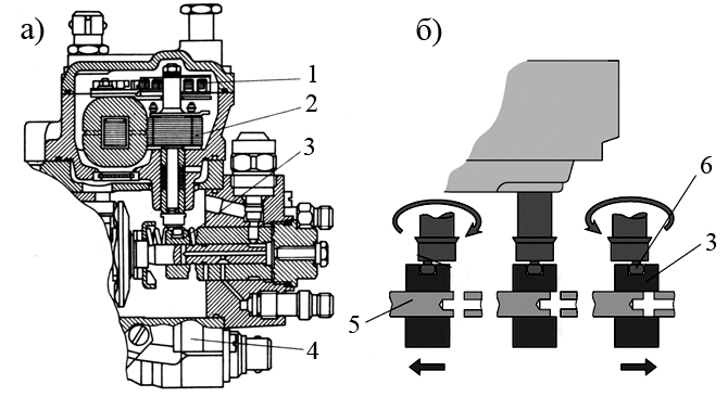
In most cases, for single-plunger pumps of the distribution type, as an actuator that regulates the cycle flow. an electromagnet 6 (Fig. 18) with a rotary core is used, the end of which is connected through an eccentric with a metering clutch 5. When current passes in the electromagnet winding, the core rotates through an angle from 0 to 60 °, respectively moving the metering clutch 5, with the help of which the cyclic filing.
Rice. 18. Detailed diagram of a single-plunger pump with electronic control:
1 - injection pump; 2 - solenoid valve for controlling the injection timing machine; 3 - jet; 4 - cylinder of the automatic injection advance; 5 - dispenser; 6 - electromagnetic device for changing the fuel supply; 7 - electronic control unit; 8 - temperature sensors, boost pressure, fuel supply position; 9 - control pedal; 10 - fuel return; 11 - fuel supply to the injector
The control of the automatic injection advance is carried out by a high-speed solenoid valve 2, which regulates the pressure of the fuel acting on the piston of the automatic machine. The valve operates in an “open-close” pulse mode, modulating the pressure depending on the engine speed. When the valve is open, the pressure decreases and the injection advance angle also decreases. When the valve is closed, the pressure increases, moving the piston of the machine in the direction of increasing the injection advance angle. The ratio of the pulses is determined by the electronic unit, depending on the operating mode and the temperature state of the engine. One of the nozzles is equipped with an induction needle lift sensor to determine the moment of injection start.
Proportional electromagnetic, torque, linear or step electric motors are used as actuators acting on the bodies that control the fuel supply to the high-pressure fuel pump, which serve as a direct drive of the fuel metering device in distribution-type pumps.
As an example, Fig. 19 shows an actuator that controls the fuel supply, which uses an electromagnet 2 with a rotary core, the end of which is connected through an eccentric to a metering clutch 3. When current flows in the electromagnet winding, the core rotates through an angle from 0 to 60 °, correspondingly moving the metering clutch 3. Its movement is monitored using sensor 1.
Rice. 19. Electromagnetic actuator of distribution type injection pump:
1 - dispenser stroke sensor; 2 - executive device (electromagnet); 3 - metering sleeve; 4 - valve for changing the angle of the beginning of injection with an electromagnetic drive; 5 - plunger; 6 - ball tip; a - section of the actuator; b - diagram of the principle of operation
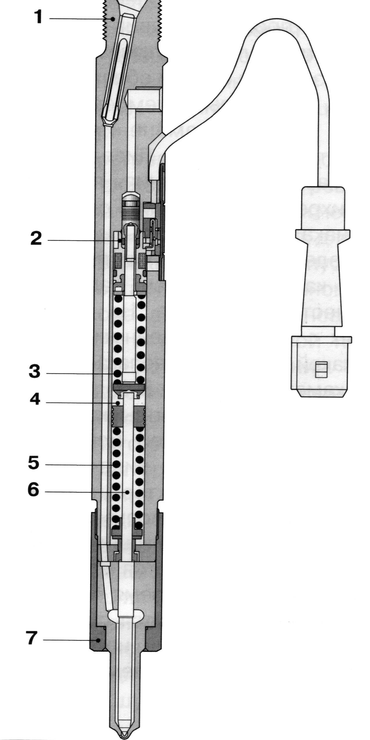
Nozzle. The moment of the start of fuel injection is a very important parameter that determines the optimal operation of a diesel engine. This makes it possible to clarify the value of the injection advance angle depending on the load and speed, to control the exhaust gas recirculation and various actuators. To determine the start of fuel injection in the electronic control systems of a single-plunger injection pump, an injector with a needle lift sensor is used (Fig. 20).
A needle lift sensor is built into the nozzle body, which consists of an excitation coil 2 and a rod (armature) 3. A reference voltage is supplied to the excitation coil by the electronic control unit so that the current in the electric circuit is kept constant, regardless of temperature changes. This current creates a magnetic field around the coil. As soon as the nozzle needle rises, the armature 3 changes the magnetic field, causing a change in the voltage signal.

Rice. 20. Diagram of a nozzle with needle lift sensors:
1 - adjusting screw; 2 - excitation coil; 3 - stock; 4 - wire; 5 - electrical connector
During the movement of the needle, the magnetic flux in the coil changes its value and induces a signal, the voltage of which is proportional to the speed of movement of the needle, but not to the magnitude of the movement. At a certain moment when the needle is raised, a peak impulse occurs, which is sensed by the electronic control unit and used to control the injection advance angle. This signal is compared with the values stored in the memory of the electronic unit for the corresponding operating conditions of the diesel engine. The electronic control unit sends a return signal to the solenoid valve connected to the working chamber of the automatic injection advance and the pressure acting on the piston of the automatic machine changes, as a result of which the piston moves under the action of the spring, changing the injection advance angle.
The conventional standard injectors in electronic injection systems have been replaced by two-spring injectors. The use of such injectors reduces engine noise.
Two-spring nozzles have two springs located one after the other in the nozzle body. At first, only one spring acts on the needle, allowing it to open at the beginning of the overpressure.
In this case, the second spring comes into contact with the thrust sleeve, preventing further needle lift. With a further increase in pressure, the thrust sleeve rises, compressing both springs and thus providing greater needle lift. A diagram of a two-spring nozzle is shown in Fig. 21.
Rice. 21. Dual spring injector with needle lift sensor for engines with direct injection:
1 - nozzle body, 2 - needle lift sensor, 3 - first spring, 4 - guide element, 5 - second spring, 6 - pressure pin, 7 - atomizer mounting nut.
Injector operation. At the beginning of the injection process, the initial lift of the needle occurs, which allows only a small amount of fuel to be fed into the combustion chamber. With a further increase in the injection pressure, the injector needle rises completely, and the main fuel injection occurs. Such a two-stage injection, indicated by the curve in Fig. 22, provides a softer combustion process and leads to a decrease in noise.
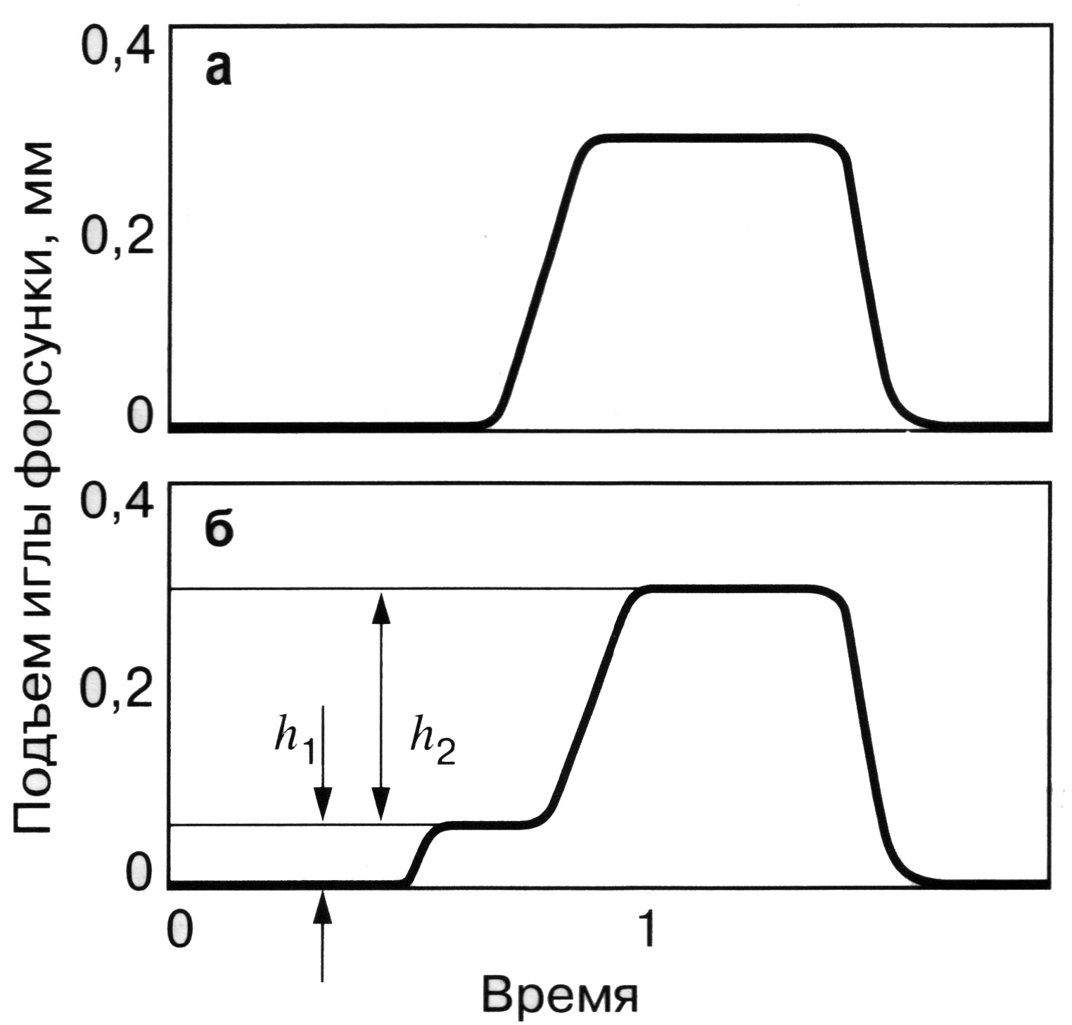
Rice. 22. Comparison of the lift characteristics of the nozzle needle:
a - standard nozzle; b - two-spring nozzle; h 1 - initial move; h 2 is the main move.
The maximum injection pressure achieved by the electronic fuel supply control based on the VE fuel pump is 150 kgf / cm 2. However, the resources of this design scheme for voltages in a complex cam drive are practically exhausted. The next generation injection pump is more advanced - VP-44.
High pressure fuel pump VP-44.
Such pumps are used on Opel Ecotec diesel models, Opel astra, Audi, Ford, BMW, Daimler-Chrysler. The injection pressure developed by pumps of this type reaches 1000 kgf / cm 2.
Scheme fuel system with this injection pump is shown in Fig. 23.
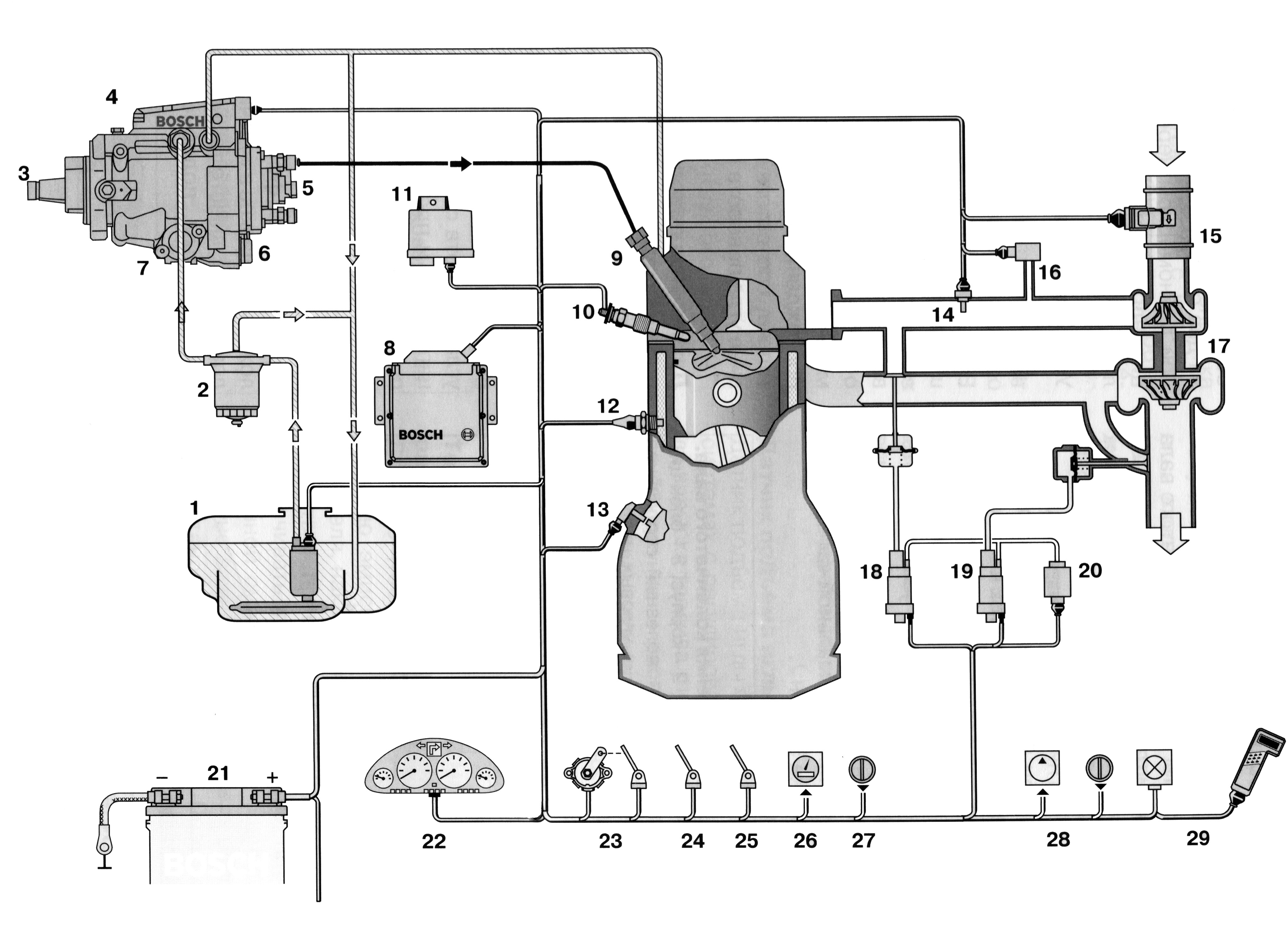
Rice. 23. Direct injection system diesel engine with injection pump VP-44:
1 - fuel tank; 2 - fine fuel filter; 3 - injection pump; 4 - ECU of the injection pump; 5 - solenoid valve for fuel supply control; 6 - solenoid valve of the injection advance angle; 7 - automatic injection advance; 8 - engine ECU; 9 - nozzle with a needle lift sensor; 10 - candle preheating with a closed heating element; 11 - ECU of glow plugs; 12 - coolant temperature sensor; 13 - crankshaft speed sensor; 14 - intake air temperature sensor; 15 - mass air flow meter; 16 - boost pressure sensor; 17 - turbocharger; 18 - exhaust gas recirculation valve drive; 19 - drive of the boost pressure control valve; 20 - vacuum pump; 21 - accumulator battery; 22 - dashboard with fuel consumption indicator, tachometer, etc .; 23 - accelerator pedal position sensor; 24 - limit switch (on the clutch pedal); 25 - brake light contacts; 26 - vehicle speed sensor; 27 - cruise control control unit; 28 - air conditioning compressor; 29 - diagnostic display with outputs for the diagnostic tester.
A feature of the given system is the combined control unit for both the injection pump and other engine systems. The control unit consists of two parts, the final stages of the power supply of the electromagnets of which are located on the body of the injection pump.
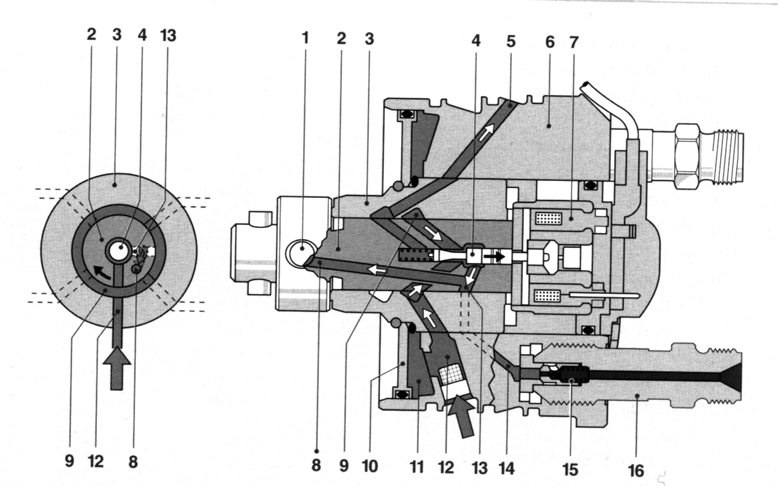
General view of the VP-44 injection pump is shown in Fig. 24.

Rice. 24. Fuel injection pump VP-44:
1 - fuel pump; 2 - sensor of frequency and position of the pump shaft; 3 - cam washer; 4 - control unit; 5 - plug block; 6 - delivery plungers; 7 - distributor rotor; 8 - solenoid valve for feed control; 9 - discharge valve; 10 - solenoid valve for setting the moment of injection start; 11 - injection advance device; 12 - sensor of the angle of rotation of the drive shaft of the injection pump.
Low pressure circuit. The fuel priming pump 17 (Fig. 25) in the VP-44 high-pressure pump of the vane type is similar to those discussed above. The fuel pressure generated by the fuel priming pump on the delivery side depends on the speed of the pump wheel. At the same time, this pressure increases disproportionately with increasing rotational speed. The pressure control valve 2 is located in the immediate vicinity of the fuel pump. The valve changes the discharge pressure generated by the fuel priming pump, depending on the required fuel consumption.
Fuel from the fuel priming pump goes to the pump section of the high-pressure fuel pump and the injection advance device.
Rice. 25. Hydraulic diagram of injection pump VP-44:
1 - diesel engine control unit; 2 - pressure control valve; 3 - piston of the pressure control valve; 4 - bypass throttling valve; 5 - outlet channel; 6 - throttle; 7 control unit for injection pump; 8 - piston damper; 9 - solenoid valve for feed control; 10 - discharge valve; 11 - nozzle; 12 - solenoid valve for setting the moment of injection start; 13 - rotor distributor; 14 - pump section of high pressure fuel pump with radial movement of plungers; 15 - sensor of the angle of rotation of the drive shaft of the injection pump; 16 - injection advance device; 17 - fuel pump.
If the created fuel pressure exceeds a certain value, the end edge of the piston 3 opens the holes located radially, and through them the fuel flow is drained through the pump channels to the inlet groove. If the fuel pressure is too low, these radial holes are closed due to the predominance of the spring forces. The spring preload therefore determines the opening pressure of the valve.
To cool the fuel priming pump and remove air from it, the fuel flows through the bypass throttling valve 4 screwed to the pump housing.
This valve removes fuel through the outlet channel 5. The valve body contains a spring-loaded ball, which allows fuel to flow out only when a certain pressure in the channel is reached.
The throttle 6 of a very small diameter, connected with the return line, is located in the valve body parallel to the main fuel return channel. It provides automatic air removal from the pump. The entire low-pressure circuit of the high-pressure fuel pump is designed so that a certain amount of fuel always flows into the fuel tank through the bypass throttling valve.
High pressure circuit. The high-pressure circuit includes a high-pressure pump, as well as a unit for distributing and regulating the magnitude and moment of the start of supply using only one element - a high-pressure solenoid valve.
The pump section of the high pressure fuel pump with a radial movement of the plungers creates the pressure required for injection up to 1000 kgf / cm 2.
It is driven through a shaft and includes (Fig. 26):
Connecting washer;
Shoes 4 with rollers 2;
Cam washer 1;
Discharge plungers 5;
Front part (head) of the distributor shaft 6.
Rice. 26. Examples of plunger arrangement:
a - for four or six cylinders; b - for six cylinders; c - for four cylinders; 1- cam washer; 2 - roller; 3 - guide grooves of the drive shaft; 4 - roller shoe; 5 - pumping plunger; 6 - distributor shaft; 7 - high pressure chamber
The torque from the drive shaft is transmitted through the connecting washer and the splined connection directly to the distributor shaft. The guide grooves 3 serve to ensure the operation of the pumping plungers 5 through the shoes 4 and the rollers 2 sitting in them in accordance with the inner profile of the cam washer 1. The number of cams on the washer corresponds to the number of engine cylinders.
In the housing of the distributor shaft, the discharge plungers are located radially, which gave the name to this type of injection pump. On the ascending cam profile, the plungers jointly squeeze the fuel into the central high-pressure chamber 7. Depending on the number of engine cylinders and the conditions of its use, there are high-pressure fuel pump options with two, three or four pumping plungers.
Distribution housing (fig. 27) consists of:
Flange 6;
Tightly inserted into the flange of the distributor sleeve 3;
Located in the distributor sleeve at the rear of the distributor shaft 2;
Locking needle 4 of the high pressure solenoid valve 7;
Accumulating membrane 10, separating the pumping and draining cavities;
High pressure line connection 16 with discharge valve 15.
Rice. 27. Housing-distributor:
1 - plunger; 2 - distributor shaft; 3 - distribution sleeve; 4 - locking needle of the high pressure solenoid valve; 5 - fuel backflow channel; 6 - flange; 7 - high pressure solenoid valve; 8 - channel of the high-pressure chamber; 9 - annular fuel inlet channel; 10 - accumulating membrane separating the pumping and draining cavities; 11 - cavity behind the membrane; 12 - low pressure chamber; 13 - distribution groove; 14 - outlet channel; 15 - discharge valve; 16 - union of the high pressure line
In the filling phase (Fig., 28, a) on the downward profile of the cams, the radially moving plungers 1 move outward, towards the surface of the cam washer. At the same time, the locking needle 4 is in a free state, opening the fuel inlet channel. Through the annular channel 9 of the low-pressure chamber and the needle channel, the fuel is directed from the fuel pump through the channel 8 of the distributor shaft and fills the high-pressure chamber. The surplus fuel flows out through the drain back channel.

Rice. 28. Schematic diagram fuel supply (positions in fig. correspond to positions in fig. 27)
In the injection phase (Fig. 28, b), the plungers 1 with the closed needle 4 move on the ascending profile of the cams to the distributor shaft axis, increasing the pressure in the high-pressure chamber.
Due to this, the high-pressure fuel moves through the channel 8 of the high-pressure chamber. Then the fuel through the distribution groove 13 (Fig. 27), which in this phase connects the distributor shaft 2 with the exhaust channel 14, the fitting 16 with the discharge valve, the high pressure line and the nozzle enters the combustion chamber of the engine ...
Fuel metering with high pressure solenoid valve.
A high-pressure solenoid valve 7 is built into the high-pressure circuit of the high-pressure pump for dosing of the cyclic feed.
At the signal of the high pressure pump control unit, voltage is applied to the solenoid coil of the electromagnet, and the armature moves the needle 4, pressing it to the saddle. If the needle is pressed against the seat, fuel enters only the high-pressure outlet channel 14 connected to the discharge valve, where the pressure rises sharply, and from there to the nozzle. The dosing of the fuel supply is determined by the interval between the moment of the beginning of the supply and the moment of opening of the solenoid valve and is called the duration of the supply.
The duration of the closing of the solenoid valve, determined by the control unit, thus regulates the value of the cyclic fuel supply. After the end of injection, the solenoid of the valve is de-energized, while the solenoid valve of the high pressure opens, and the pressure in the circuit decreases, stopping the supply of fuel to the injector.
Excess fuel, which is pumped up until the plunger roller passes the upper point of the cam profile, is directed through a special channel into the space behind the accumulating membrane. The high pressure surges that occur in the low pressure circuit are damped by an accumulation diaphragm. In addition, this space retains the stored fuel for the filling process before subsequent injection.
To stop the engine, the high pressure injection is completely shut off by the solenoid valve. Consequently, an additional stop valve is not required, as is the case in distributor injection pumps with control of the regulating edge.
Damping of pressure waves by means of a discharge valve with throttling of the return flow. The delivery valve 15 with throttling of the reverse flow at the end of the next injection of fuel prevents a new opening of the injector nozzle, which excludes the occurrence of post-injection, which is possible as a result of the appearance of pressure waves or their reflections. Injection has a negative effect on the exhaust gas toxicity.
When the flow starts, the valve cone opens the valve. The fuel is now pumped through the union and the high pressure line to the injector. At the end of the injection, the fuel pressure drops sharply, and the return spring presses the valve cone against its seat. The back pressure waves arising when the injector is closed are damped by the throttle of the discharge valve, which prevents fuel injection into the combustion chamber.
Fuel injection advance device. The combustion process is most favorable, as well as the best power output of the diesel engine, occurs only when the moment of the beginning of combustion corresponds to a certain position of the crankshaft or piston in the cylinder. The task of the injection advance device is to increase the angle of the beginning of the fuel supply when the crankshaft rotational speed increases. This device, consisting of a sensor for the rotation angle of the injection pump drive shaft, a control unit and an electromagnetic valve for setting the injection start time, provides the optimal injection start time in accordance with the engine operating conditions, thereby compensating for the time shift determined by the reduction in the injection and ignition period when increasing the speed.
Injection advance device equipped with hydraulic drive, built into the lower part of the injection pump body across its longitudinal axis (Fig. 29).
Fig. 29. Injection advance device:
1 - cam washer; 2 - ball pin; 3 - plunger for setting the injection advance angle; 4 - underwater / branch channel; 5 - control valve; 6 - vane fuel pump; 7 - fuel outlet; 8 - fuel inlet; 9 - supply from the fuel tank; 10 - spring of the control piston; 11 - returnable spring; 12 - control piston; 13 - annular chamber of the hydraulic stop; 14 - throttle; 15 - solenoid valve for setting the moment of injection start (in the closed position).
The cam washer 1 enters with its ball pin 2 into the transverse hole of the plunger 3 so that the translational movement of the latter turns into a rotation of the cam washer. In the middle of the plunger there is a control valve 5, which opens and closes the control holes in the plunger. Along the axis of the plunger 3 is a control piston 12 loaded with a spring 10, which sets the position of the control valve.
Across the axis of the plunger there is a solenoid valve 15 for setting the start of injection. The injection pump control unit acts on the plunger of the injection advance device with the help of this valve (Fig. 30), to which current pulses of constant frequency and variable duty cycle are continuously supplied. The valve changes the pressure acting on the control piston.
Rice. 30. Solenoid valve for setting the start of injection:
1 - valve seat; 2 - closing direction; 3 - valve needle; 4 - anchor of the electromagnet; 5 - coil; 6 - electromagnet.
Regulation of the start of injection. Depending on the operating conditions of the engine (load, crankshaft speed, coolant temperature), the diesel engine control unit sets the required injection advance angle, which is determined by the corresponding field of characteristics. To provide the required injection advance angle, the cam washer rotates through a certain angle.
The injection start regulator in the injection pump control unit constantly compares the actual value of the injection start moment with the preset one. If the difference between these signals is higher than the allowable value, the regulator changes the injection start moment using the solenoid valve for setting the injection start timing. Information about the actual moment of the start of injection is transmitted by the signal from the angle sensor of the drive shaft of the injection pump or, alternatively, by the signal from the sensor of the needle lift of the injector nozzle.
Setting an early injection advance. When the engine is not running, plunger 3 (Fig. 29) for setting the injection advance angle is set to late injection thanks to the return spring 11. When the engine is running, the fuel pressure inside the injection pump is changed by the pressure control valve depending on the crankshaft speed. The pressure of the fuel passing through the throttle 14 into the annular chamber 13 of the hydraulic stop shifts, with the solenoid valve 15 closed, the control piston 12 in the direction of the "earlier" position, overcoming the force of the piston spring 10. Due to this, the control valve 5, which is connected to the control piston, is also shifted to an earlier injection advance angle, opening channel 4 leading to the chamber behind the plunger 3.
Fuel entering through this channel presses on the plunger, moving it in the direction of the "earlier" position. The axial movement of the plunger 3 is converted through the ball pin 2 into the rotation of the cam washer 1 relative to the injection pump drive shaft, which leads to an earlier run of the rollers onto the cams and provides an earlier start of injection. The possibility of setting an earlier injection advance angle is up to 20 ° of the cam washer rotation angle (respectively, 40 ° of the crankshaft rotation angle).
Setting the late advance of injection. The solenoid valve 15 for setting the start of injection opens if it receives a signal from the injection pump control unit. When it is opened, the control pressure in the annular chamber 13 of the hydraulic stop is reduced.
The control piston 12 is moved by the force of the spring 10 in the direction of the "later" position. When the control valve 5 opens the control hole connected to the channel 4, then the fuel begins to flow out of the cavity behind the plunger 3. The force of the spring 11 and the reactive moment on the cam washer 1 now press on the plunger 3 in the direction of the position " later, ”that is, to the starting position.
Control pressure control. Since the solenoid valve 15 is able to quickly open and close, it works as an adjustable throttle and constantly influences the control pressure so that the plunger 3 can take any position in the working range "earlier - later". In this case, the ratio of the opening time of the solenoid valve to the total duration of the working cycle of movement of the needle of the solenoid valve is determined by the injection pump control unit.
For example, if the control plunger is to be set to the "earlier" position, this ratio is changed by the control unit so that the valve open position is reduced. In this case, a certain amount of fuel passes through the solenoid valve, and the plunger moves towards the "earlier" position.
1. Title of the work.
2. Diagram of the power supply system with single-plunger high-pressure distribution fuel pumps of the high-pressure fuel pump without electronic control from Bosch VE.
3. Diagram of the power supply system with single-plunger high-pressure distribution fuel pumps of the electronically controlled injection pump from Bosch VE.
4. Diagram of the fuel pump Bosch VE.
5. Low pressure fuel pump and control valve.
6. Phases of fuel supply.
7. Scheme of the all-mode regulator.
8. Electronically controlled single-plunger high-pressure fuel distribution pumps.
9. Nozzle with needle lift sensor.
10. Dual-plunger injector with needle-level sensor for engines with direct fuel injection.
11. Injection advance device.
Control questions
1. Advantages and disadvantages of power supply systems with single-plunger high-pressure distribution fuel pumps of high-pressure fuel pumps without electronic control from Bosch VE.
2. Advantages and disadvantages of power supply systems with single-plunger high-pressure fuel distribution pumps, electronically controlled injection pump from Bosch VE.
3. Purpose fuel filter fine fuel cleaning.
4. Purpose and design of the low pressure fuel pump and control valve.
5. Design and principle of operation of the power supply system injector with single-plunger high-pressure distribution fuel pumps of the high-pressure fuel pump without electronic control from Bosch VE.
6. Design and principle of operation of the power supply system injector with single-plunger high-pressure distribution fuel pumps of the electronically controlled injection pump from Bosch VE.
7. Purpose and types of glow plugs. Advantages and disadvantages.
8. Purpose and principle of operation automatic regulator rotation frequency.
9. The device of the nozzle of the power supply systems with single-plunger high-pressure distribution fuel pumps of the electronically controlled injection pump from Bosch VE.