Earbud Selection Chart
On early engines, the upper and lower liners were of the same thickness.
On later engines, the bearing operating clearance was significantly reduced and in order to meet this condition, four different bushings are used, which are indicated by a colored mark on the end. The color of the mark indicates the thickness of the liner. The upper shell on all bearings is the same size, and the working clearance is adjusted by setting the lower shell to the required thickness.
Engines 1500 cm 3, 1761 cm 3 and 1905 cm 3
Engines 1998 cm 3
On most recent engines, new liners can be selected taking into account the marks on the cylinder block. In the absence of marks, the liners can be picked up only by measuring the working gap.
The cylinder block marks are on the left side of the block, and the crankshaft marks are on the end of the crankshaft bridge. These marks can be used to select the required liner thickness as follows.
There are two lines of identification on the crankshaft and cylinder block: the barcode used by Peugeot in production and a series of five designations. The first designation in the sequence refers to the size of the liner number 1. The last designation in the sequence (accompanied by an arrow) refers to the size of number 5 of the insert (see Fig. Location of the mark on the block of cylinders and crankshaft). Determine the designation number from a specific journal of the crankshaft and the bearing bore of the cylinder block.
On the upper axis of the nomogram, the designation of the crankshaft is marked and through this point is drawn vertical line... On the left vertical axis of the nomogram, the designation of the cylinder block is marked and a horizontal line is drawn through this point. The point of intersection of the lines indicates the size of the liner to provide the required clearance (see Fig. Earbud Selection Chart).
For example, the nomogram shows that the crankshaft points to 6, the block points to H, the intersection point within the red area determines that the red (Class D) is the most suitable for obtaining the required clearance.
An article about installing a crankshaft on a VAZ 2107 will be useful for both a beginner and an experienced driver. The guide will be accompanied by photographs and detailed description all actions.
We remove the crankshaft from the VAZ 2107 car to replace it or replace the crankshaft liners.
How to remove a crankshaft from a VAZ 2107
1. First of all, we install the car on a viewing pit or overpass.
2. Remove the sump from the car.
3. Remove the holder with an oil seal from the VAZ 2107 cylinder block.
4. Remove the drive cover camshaft with a gasket and a chain from the crankshaft sprocket.
5. We mark the relative position of the connecting rods relative to their caps and the main bearing caps relative to the VAZ 2107 cylinder block.
6. Using a 14 mm socket wrench, unscrew the two connecting rod cover nuts.

7. Remove the connecting rod cover with the liner.

8. Disconnect the remaining connecting rods from the crankshaft and move them up.

9. We take out the liners from the connecting rods and their caps.
10. Using a 17 mm socket wrench, loosen the bolts of the crankshaft main bearing caps.
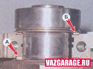
11. After unscrewing the two bolts, remove the rear main bearing cover. Two thrust half rings are installed in the grooves of the rear support of the crankshaft. Front ring A - steel-aluminum, and rear B - metal-ceramic. The rings can be removed by pressing on their ends with a thin screwdriver.
12. Turn off the bolts of the remaining main bearing caps, keeping the crankshaft from falling. We remove the covers one by one and take out the crankshaft from the crankcase of the VAZ 2107 engine. All cover liners (except for the third) installed in the beds of the main bearings have a groove. On the main bearing caps, there are marks corresponding to their serial number (counting from the toe of the crankshaft), facing the left side of the VAZ 2107 cylinder block. On the fifth cover there are two marks spaced along the edges.

Mark on the cover of the first main bearing
13. To replace, remove the crankshaft main bearing shells from the cylinder block and covers.


The main (A) and connecting rod (B) bearings of the crankshaft
Note: If there are any cracks on the necks or cheeks, the crankshaft of the VAZ 2107 car must be replaced.
14. With a micrometer we measure the diameters of the main and connecting rod journals of the crankshaft and compare with the data given in the table.
If the wear or ovality is greater than 0.03 mm, then the crankshaft journals must be ground in a specialized workshop, where the necessary equipment is available (it is also necessary to check the axial runout of the main surfaces of the crankshaft there). After grinding the crankshaft, we re-measure the diameters of the crankshaft journals to determine the repair size of the liners.
Do-it-yourself crankshaft installation on a VAZ 2107
1. We wash the crankshaft in kerosene and blow through its internal cavities with compressed air. We install new crankshaft main bearing shells of nominal or overhaul size. On the outer cylindrical surface of the liners, numbers are stamped indicating the repair size: 025 - the first repair, under the crankshaft neck, reduced in diameter by 0.25 mm. Accordingly, for the second, third and fourth repair sizes, the values will be: 050, 075, 100.
It is easy to distinguish connecting rod bearings from indigenous ones. Annular grooves are made on the upper main bearing shells (except for the middle one). In addition, the center mount crankshaft bushings are wider than the rest. Crankshaft connecting rod bearings are all the same and interchangeable, diameter connecting rod bearings less than the diameter of the root. To increase the contact area, there are no annular grooves on the connecting rod bushings.
2. Install thrust half rings in the grooves of the bed of the fifth main bearing with grooves to the crankshaft. Half rings are made of normal thickness (2.310-2.360 mm) and increased (2.437-2.487 mm).
3. We check the axial clearance between the thrust half rings and the thrust surfaces of the crankshaft, which should be within 0.06-0.26 mm. If the gap exceeds the maximum allowable (0.35 mm), replace the thrust half rings with new ones, increased by 0.127 mm.
4. Lubricate the connecting rod and main journals of the crankshaft engine oil and install the crankshaft into the cylinder block.
5. In accordance with the marks, install the main bearing caps and tighten the bolts of their fastening to a torque of 68.4-84.3 Nm. We check the free rotation of the crankshaft.
6. Install connecting rods with bushings and covers on the crankshaft. We tighten the fastening nuts to a torque of 43.4-53.5 Nm.
7. Install the engine sump on the VAZ 2107.
8. Install the holder with the oil seal on the cylinder block.
9. Installing the rest of the removed parts to the vehicle is carried out in reverse order.
10. Adjust the tension of the timing chain.
11. Adjust the tension of the alternator drive belt.
12. On carburetor engine We check the VAZ 2107 and, if necessary, adjust the ignition timing.
The diameters of the connecting rod and main journals of the crankshaft of the VAZ 2107

).
We shoot fuel pump(cm. ).
Remove the ignition distributor (see).
Having sketched the connection procedure, we disconnect the hoses and wires from the engine, we lighten the cylinder block, for which we remove the block head (see).
We remove the generator (see).
Remove the starter (see).
Remove the coolant pump (see).
We unscrew the upper or lower nuts for securing the engine support cushion (see).
We unscrew the bolts securing the clutch housing to the engine.
We install the cylinder block on the stand.
Remove the clutch (see).
Remove the pulley, camshaft drive cover, chain and oil pump drive gear (see).
Remove the drive roller auxiliary units(cm. ).
Remove the flywheel and the crankshaft rear collar holder (see).
We take out the other three pistons in the same way.
We disassemble the crankshaft (see).
We take out the old main bearing shells. We wash in diesel fuel or kerosene block and crankshaft. We blow out their internal cavities and oil channels with compressed air.
We wipe the main bearing seats with a napkin and install new liners of the corresponding category (nominal or repair).
We lubricate the main and connecting rod journals of the crankshaft with an engine or transmission oil and install the shaft into the block.
We check the rotation of the crankshaft. It should be light and smooth, without jamming and backlash.
We install new steel-aluminum liners in the lower heads and caps of the connecting rods (see).
We put on the connecting rod cover and tighten the bolts with a torque wrench (see).
Further assembly of the engine is carried out in the reverse order of disassembly.
The VAZ 2106 crankshaft is a part of the crank mechanism that plays a very significant role in the car. In order to perform the installation of the crankshaft as efficiently as possible, you will need a wide variety of tools, for the most part sold in any specialized auto store. Please note that when assembling the piston connecting rod motors VAZ 2106 has its own characteristics.
In cars that were assembled before the 90s of the last century, the piston must be aligned with the connecting rod in such a way that the applied mark in the form of the letter P is located on the side of the connecting rod where the oil outlet is located. Engines produced in a later period have no connecting rod bores at all. And this applies not only to connecting rod engines, but also to their liners. Also keep in mind during operation that the piston with the crankshaft connecting rod can be connected in almost any position.
Replacing the crankshaft oil seal
The main sign of the need to replace the oil seal is the contamination of the engine compartment. Breakdown occurs at the moment when the tightness of the assembly is broken, due to which the damaged oil seal will begin to leak lubricant mixed with butter. As a result, hitting rotating parts, the mixture is sprayed all over the engine compartment.
In particular, a signal that an urgent replacement of the front oil seal liners is necessary is the direct ingress of oil on the pulley and its further splashing in the front of the engine. If oil leaks in the rear oil seal, splashing occurs on the flywheel in the clutch housing. Reasons for replacement:
- natural wear and tear;
- skewed installation, due to which cracks may appear on the case;
- mechanical damage;
- violation of the integrity of the surface as a result of severe overheating of the engine;
- marriage.
You can replace the crankshaft oil seals on your own, this will not only significantly save time and money spent on repairs in the workshop, but also gain invaluable experience. Replacing the crankshaft oil seal is a routine procedure to achieve optimum engine performance.
Oil seals are a type of seal that seals on moving parts. The most correct would be to call the crankshaft oil seal a reinforced cuff. Its role in the operation of the engine is very significant, and therefore any failures in the stable operation of the crankshaft oil seal will lead to undesirable consequences. Even if the degree of its displacement from the standard place is insignificant, oil will start to leak in the car.
According to statistics, the installation of a new oil seal should be carried out at least once over a period of 3 years. However, replacement of the packing bushings may be required much earlier. It all depends on the general condition of the parts and the conditions under which the vehicle is used.
Preparation for replacing liners and direct installation of the crankshaft
After the hood and battery are removed from the VAZ 2106, the oil and coolant must be carefully drained. Then remove parts such as radiator, thermostat, carburetor, fuel pump and ignition distributor. For yourself, be sure to note in what order they are filmed. Next, you need to remove all adjacent hoses and wires from the engine along with the cylinder head.
In addition, disconnect parts such as the alternator, starter, coolant pump, upper nuts responsible for securing support cushion engine and the bolts securing the clutch housing to the engine. The order in which the disconnection is made must be strictly followed. During operation, the cables of the lifting device must be fixed to the block and carefully lifted.
Then, placing the jack under the gearbox, begin to gently rock the block in order to gradually disconnect it from the clutch housing. It will be necessary to remove the cylinder block, clutch, pulley, camshaft wire cover, oil pump parts, accessory drive shaft, flywheel and rear crankshaft seal holder.
With a 10 key, you need to unscrew all the bolts that secure the oil pan to the cylinder block, and remove it together with the seal gasket. Disconnect the oil pump. Using the 14 head, unscrew the nuts that secure the connecting rod cover, and then remove it. Then take a hammer, rest against the connecting rod with the handle, push the pistons out of the cylinders. Next, take the head 17 and unscrew the bolts with which the crankshaft is attached to the cover. Keeping score from the toe of the crankshaft, according to the number marks, disconnect all subsequent covers. Keep in mind that on the 5th lid there are two marks at once on both sides.
Only now you can remove the crankshaft itself and remove the two half rings of the crankshaft thrust bearing. When working, it must be remembered that the metal liners installed on the beds of all bearings, with the exception of the 3rd, are equipped with a groove.
We remove the crankshaft to replace it or replace the liners.
1. We install the car on the inspection pit or overpass (see "Preparing the car for TO and repair").
2. Remove the oil pan of the engine (see "Oil pan - removal and installation").
3. Remove the holder with the oil seal from the cylinder block (see "Rear crankshaft oil seal - replacement").
4. Remove the camshaft drive cover with a gasket and the chain from the crankshaft sprocket (see "Timing chain - replacement").
5. We mark the relative position of the connecting rods relative to their caps and the main bearing caps relative to the cylinder block.
6. Socket wrench by 14 mm we unscrew the two nuts securing the connecting rod cover.
7. Remove the connecting rod cover with the liner.

8. Disconnect the remaining connecting rods from the crankshaft and move them up.

We take out the liners from the connecting rods and their caps.
9. Socket wrench by 17 mm we loosen the bolts of the crankshaft main bearing caps.

10. After unscrewing the two bolts, remove the rear main bearing cover. Two thrust half rings are installed in the grooves of the rear support of the crankshaft. Front ring A- steel-aluminum, and the rear B- cermet. The rings can be removed by pressing on their ends with a thin screwdriver.

11. Unscrew the bolts of the remaining main bearing caps, keeping the crankshaft from falling. We remove the covers one by one and remove the crankshaft from the crankcase. All cap shells (except for the third) installed in the main bearing beds have a groove. On the main bearing caps, there are marks corresponding to their serial number (counting from the toe of the crankshaft), facing the left side of the cylinder block. The fifth cover has two marks spaced along the edges.
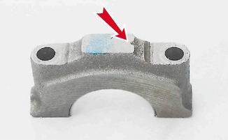
Mark on the cover of the first main bearing
12. To replace, remove the crankshaft main bearing shells from the cylinder block and covers.

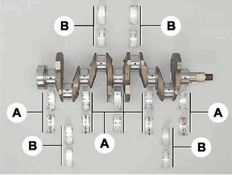
The main (A) and connecting rod (B) bearings of the crankshaft
Note
If there are any cracks in the journals or cheeks, the crankshaft must be replaced.
13. We measure the diameters of the main and connecting rod journals with a micrometer and compare with the data given in table. 8.1.1. If the wear or ovality is more than 0.03 mm, then the journals must be ground in a specialized workshop, where the necessary equipment is available (it is also necessary to check the axial runout of the main surfaces of the crankshaft there). After grinding, we re-measure the diameters of the crankshaft journals to determine the repair size of the liners.
Table 8.1.1. Crankshaft journal diameters
|
Nominal size (mm) |
Repair (reduced) dimensions (mm) |
|||
|
Connecting rod journals |
||||
|
Root necks |
||||
Installation
1. We wash the crankshaft in kerosene and blow through its internal cavities with compressed air. We install new crankshaft main bearing shells of nominal or overhaul size. On the outer cylindrical surface of the liners, numbers are stamped indicating the repair size: 025 - the first repair size, under the crankshaft journal, reduced in diameter by 0.25 mm. Accordingly, with the second, third and fourth repair dimensions, the values will be: 050, 075, 100. It is easy to distinguish the connecting rod bearings from the indigenous ones. Annular grooves are made on the upper main bearing shells (except for the middle one). In addition, the bushings of the middle support are wider than the rest. The connecting rod bearings are all the same and interchangeable, their diameter is less than the diameter of the main ones. To increase the contact area, there are no annular grooves on the connecting rod bushings.
2. Install thrust half rings in the grooves of the bed of the fifth main bearing with grooves to the crankshaft. Half rings are made of normal thickness (2.310-2.360 mm) and increased (2.437-2.487 mm).
3. We check the axial clearance between the thrust half rings and the thrust surfaces of the crankshaft, which should be within 0.06-0.26 mm. If the gap exceeds the maximum allowable (0.35 mm), replace the thrust half rings with new ones, increased by 0.127 mm.
4. Lubricate the connecting rod and main journals of the crankshaft with engine oil and install the shaft in the block.
5. In accordance with the marks, we install the main bearing caps and tighten the bolts of their fastening to a torque of 68.4-84.3 Nm. We check the free rotation of the shaft.
6. Install connecting rods with bushings and covers on the crankshaft. We tighten the fastening nuts to a torque of 43.4-53.5 Nm.
7. Install the sump of the engine crankcase (see "Sump of the engine crankcase - removal and installation").
8. Install the holder with the oil seal on the cylinder block (see "Rear crankshaft oil seal - replacement").
9. Installing the rest of the removed parts is carried out in reverse order.
10. Adjust the chain tension (see "Timing chain - replacement).
11. Adjust the tension of the alternator drive belt (see "Alternator drive belt - tension adjustment and replacement").
12. On a carburetor engine, check and, if necessary, correct the ignition timing (see "Ignition timing - check and adjustment").