Complexity
Tool1 - 3 h
Instruments:
Parts and consumables:
- Oil filter
- Engine oil
- Rags
Tool:
- Open-end spanner 10 mm
- Medium Phillips screwdriver
- Medium flat screwdriver
- Flat screwdriver large
- Set of flat probes
- Micrometer
- Valve adjuster
- Valve tappet retainer
- Tweezers
Parts and consumables:
- Cylinder head cover gasket
- Shims
Note:
We measure and adjust the clearances on a cold engine.
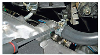
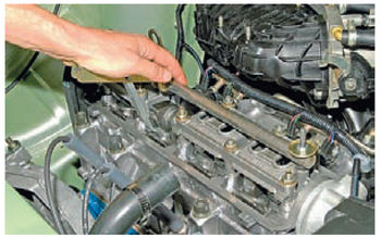
1. Removing the engine screen. Disconnect the throttle valve drive cable from the throttle assembly sector. Having unscrewed the three fastening nuts, we remove the bracket for the throttle valve drive cable and move the bracket with the cable to the side.
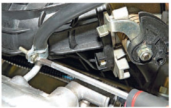
2. Using a Phillips screwdriver, we loosen the tightening of the clamp of the lower crankcase ventilation hose and remove the hose from the branch pipe of the cylinder head cover.

3. Using a Phillips screwdriver, we loosen the tightening of the crankcase ventilation hose clamp (main circuit) and remove the hose from the cylinder head cover nipple.
4. Using a Phillips screwdriver, we loosen the tightening of the crankcase ventilation hose clamp (idle circuit) and disconnect the hose from the cylinder head cover pipe.
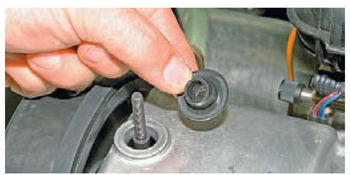
5. Using a 10 key, unscrew the two nuts securing the cylinder head cover and remove the washers.
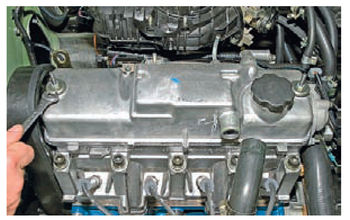
6. Remove the two rubber bushings.
7. Remove the cylinder head cover. Remove the front timing belt cover.

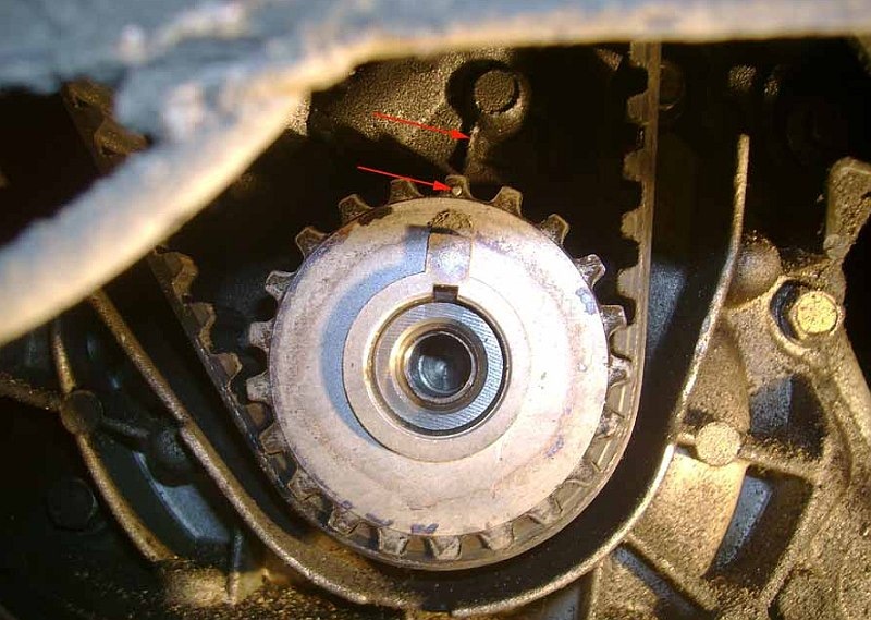
8. We turn crankshaft by the bolt of the generator drive pulley fastening clockwise until the alignment marks on toothed pulley camshaft and rear timing belt cover.
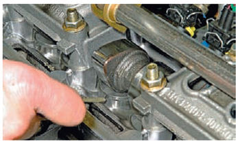
9. Then we turn the crankshaft clockwise another 40-50 ° (2.5-3 teeth on the camshaft pulley). In this position of the shafts, we check the clearances at the first and third cams of the camshaft with a set of feelers.
10. The gap between the camshaft cams and the shims should be 0.20 mm for the intake valves and 0.35 mm for the exhaust valves. Clearance tolerance for all cams is ± 0.05 mm. If the clearance differs from the norm, then on the studs of the bearing housings of the camshaft we install a device for adjusting the valves.
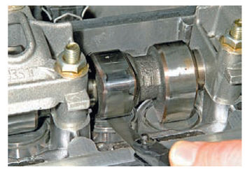
11. We unfold the pusher so that the slot in its upper part is facing forward (in the direction of the car).
12. We introduce the "canine" of the device between the cam and the pusher.
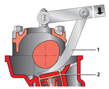
Fixture installation diagram:
1 - device;
2 - pusher.
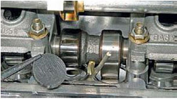
13. Pressing down on the lever of the device, we sink the pusher with a "fang".
14. We install between the edge of the pusher and camshaft a lock that holds the pusher in the lower position. We transfer the device lever to the upper position.
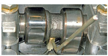

Fixing the valve pushers when replacing the adjusting washer:
1 - retainer;
2 - adjusting washer.
15. With tweezers, pry through the slot and remove the adjusting washer.

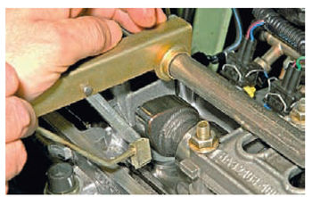
16. If there is no device for adjusting the valves, you can use two screwdrivers. Using a powerful screwdriver, leaning on the cam, we squeeze the pusher down. Insert the edge of another screwdriver (with a blade width of at least 10 mm) between the edge of the pusher and the camshaft, fix the pusher and remove the adjusting washer with tweezers.
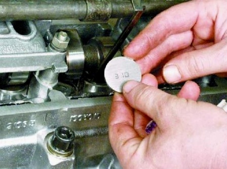
17. The gap is regulated by the selection of an adjusting washer with the required thickness.
18. For this, we measure the thickness of the removed washer with a micrometer. The thickness of the new adjusting washer is determined by the formula:
H = B + (A-C), mm
"A" - measured clearance;
"B" is the thickness of the removed washer;
"C" - nominal clearance;
"H" is the thickness of the new washer.

19. The thickness of the new washer is marked on its surface with an electrograph. We install a new washer in the pusher with the marking down and remove the retainer.
![]()
20. Check the gap again. When properly adjusted, the 0.20 or 0.35 mm stylus should fit into the gap with a slight pinch. Sequentially turning the crankshaft half a turn, we check and, if necessary, adjust the clearances of other valves in the sequence indicated in the table.
![]()
21. We assemble the engine in the reverse order. Before installing the cylinder head cover, replace its gasket with a new one.

The article is missing:
- Photo of the instrument
- Photos of parts and consumables
- High-quality photos of the repair
For normal operation of the engine, there is a gap between the valve stem and the adjusting bolt of the tappet or rocker arm, which guarantees a tight fit of the valve in its seat. The provided clearance compensates for linear deformations of the parts of the gas distribution mechanism that occur under the influence of temperature changes during the engine's working process. Because of this, the gap is called thermal. The value of the thermal gap changes with the operation of the engine due to wear of the parts of the gas distribution mechanism. Wear of the rubbing surfaces of parts transmitting force to the valve from the camshaft cam (pushers, rods, rocker arms, and adjusting bolts) leads to an increase in the previously installed clearance. At the same time, wear of the working chamfer and valve seat leads to a decrease in this clearance. The specified change in the clearance in the valves requires their systematic check and timely adjustment.
The size of the thermal gap is determined by design features and for each type of engine is stipulated by the technical conditions. Work on checking and adjusting the thermal clearances of the valves should be carried out every 6000 km of run, as well as at the first signs of malfunctions in the operation of the valve mechanism. During the running-in period of a new engine or after its repair, adjustment work should be carried out in a shorter time, the first adjustment after 300 km, the second after 1000 km of run.
Adjusting the thermal clearances of the 407 engine. The thermal clearance between the valve tip and the rocker arm adjusting bolt depends on the temperature of the engine components, especially the cylinder head. So, when the engine warms up and increases its temperature regime by 60 - 700 the thermal gap is increased by 0.1 - 0.12 mm. When operating a car in winter, this temperature difference of engine parts can reach a large value, the thermal gap can be significantly reduced in comparison with the established gap. Therefore, adjustment work should be carried out at an engine temperature in the range of 15 - 200 above zero. At this temperature, thermal. the clearance should have the following values: for exhaust valves - 0.20 mm; for inlet valves - 0.15 mm. To carry out the adjustment work, you must have the following tools: double-sided wrench 11 X 14 mm; tubular socket wrench 14 mm; special socket wrench 5 mm; screwdriver and starting handle. The order of work is as follows.
1. For the convenience of approach with the adjusting keys to the bolts of the third and fourth rocker arms, remove the air pipe of the carburetor and set aside the supply fuel pipe.
2. Unscrew the two thumbs and remove the covers of the hatches of the cylinder head casing, taking care not to damage the cork gasket.
3. Loosen the screw securing the inspection window cover on the clutch housing (Fig. 1) and move the cover 3 aside.
4. Turning the engine crankshaft with the starting handle, set the piston of the first cylinder to the uppermost position during the compression stroke. This position can be determined by the following features:
a) if the engine was not disassembled before adjustment and was in working condition, then during the compression stroke in the first cylinder, the current-carrying plate of the rotor should be facing towards the low voltage wire terminal, fixed on the body of the breaker-distributor;
b) the compression stroke can be determined by observing the sequence of the rocker arms or pusher rods during slow rotation of the crankshaft. Immediately after the inlet valve of the first cylinder is closed, the compression stroke begins. In this case, the outlet valve is also closed. When the valves of the first cylinder are closed, the rocker arms remain stationary as the crankshaft rotates, therefore, the nearest mark on the flywheel will correspond to the position of the piston at the end of the compression stroke in the first cylinder.
5. Turning the crankshaft slowly, align mark 2 with designation - c. m. t. on the rim of the flywheel with the tip of the pin 1, fixed in the clutch housing. The mark is visible through an open hatch in the clutch housing.
b. Check with a flat feeler the value of the thermal gap in successive valves: the first outlet. Second and third intake and fifth exhaust. In this case, it is necessary to select the gaps in the chain of connections pusher - rod - rocker arm, pulling up the rocker arm by the adjusting bolt. Check the condition of the valve tip surface before adjusting. In the process of wear, a dimple is formed in the center of this surface, the size of which the flat probe does not catch, and, therefore, the measured value of the gap will be inaccurate. If worn, the valve tip should be replaced or ground before adjusting.
7. Adjust the clearance in the following order (Fig. 2). Use a 14 mm socket wrench to loosen the lock nut 2 of the adjusting bolt. Checking the clearance with a flat feeler, turn the adjusting bolt with a 5 mm wrench, loosening or tightening it until the nominal clearance is obtained. While holding the adjusting bolt in the installed position with a 5 mm wrench, tighten the locknuts and check the gap again with a feeler gauge. Tighten the lock nut more securely and finally check the clearance. In this position of the crankshaft, adjust all indicated valves.
8. Turn the engine crankshaft exactly one revolution until the mark on the flywheel rim is again aligned with the pin, as previously done. In this position, the piston of the fourth cylinder should be in the uppermost position during the compression stroke. Turn and adjust the remaining four valves, i.e. the fourth outlet, sixth and seventh inlet and eighth outlet.
Adjustment of thermal clearances on the engine model 402. The value of thermal clearances between the valve stem and the adjusting bolt of the pusher must be kept within the following limits: for the inlet valve - 0.13 - 0.15 mm. for the exhaust valve - 0.18 - 0.20 mm. The measurement of the gap size should be carried out on a cold engine at an average cylinder block temperature of + 18 ". 11 X 14 mm, flat feeler The clearances are adjusted in the following order.
1. Remove the carburetor by first disconnecting the carburetor fuel supply pipe and the air filter pipe.
2. Remove the fine oil filter by disconnecting the drain and delivery pipes.
3. Remove the inlet and outlet pipes, having previously disconnected from the exhaust pipe of the muffler.
4. Disconnect the fine oil filter drain pipe from the valve box cover.
5. Open the valve box cover, taking care not to damage the plug gasket.
6. Turning the engine crankshaft with the starting handle, set the piston of the first cylinder to the uppermost position during the compression stroke (performed in the same way as described above for the 407 engine).
7. Adjust the thermal clearance between the adjusting bolt and the valve stem for the first exhaust valve, the second and third intake valve, and the fifth exhaust valve.
Adjust the clearance in the following order. Loosen the adjusting bolt locknut with a 15 mm wrench, while holding the pusher against rotation with a 17 mm wrench. Then, checking the gap with a flat feeler. with a 12 mm wrench, rotate the head of the adjusting bolt, holding the pusher with a 17 mm wrench, until the required clearance is obtained.
8. In the installed position of the adjusting bolt, tighten the lock nut, holding the adjusting bolt from rotation, and re-check the clearance.
9. Without turning the crankshaft, adjust the indicated valves (first, second, third and fifth).
10. Turn the crankshaft exactly one turn until the mark on the flywheel is again aligned with the clutch housing pin and adjust the remaining valves: the fourth exhaust, sixth and seventh intake and eighth exhaust. Adjustment of the thermal clearance in the valve mechanism.
Over time, a knock appears in the valve mechanism of the ZAZ car engines, which is not eliminated by adjusting the thermal clearances. It is caused by an increased axial clearance of the rocker arms of the exhaust valves (unlike the rocker arms of the intake valves, they do not have spacer springs that automatically eliminate the clearances). The gaps can be eliminated by installing washers on the roller between the spacers and the rocker arms. In this case, you can use the adjusting washers designed for the pins of the front suspension strut of the ZAZ-965A car, since they have high wear resistance (made of manganese steel) and are suitable in size for the MoMZ-966A engine (30 hp). For MoMZ-968 engines, the inner diameter of the washers must be increased with a file to 18 mm.
The thickness of the washers can be adjusted by grinding on an abrasive wheel so that, after assembly, the rocker arm wobbles without binding or noticeable axial play.
REFERENCES
Zhiguli cars VAZ 2104, 2105, 2107. Device. Repair. Moscow transpot 1992.
VAZ 2106 Repair manual. Moscow. Livre 1996.
Za Rulem magazine 1997. Moscow.
The size of the clearances on a cold engine should be:
For inlet valves - 0.25 ... 0.30 mm;
For exhaust valves - 0.35 ... 0.40 mm.
For the 1st, 2nd, 3rd and 4th cylinders, the front valve is the intake valve, and for the 5th, 6th, 7th and 8th cylinders - the exhaust valve.
Adjust the clearances on a cold engine. Before adjusting the thermal clearances, check the tightening torques of the cylinder head bolts and the rocker arm nuts. Thermal clearances regulate simultaneously in two cylinders with closed valves. When adjusting, the crankshaft should be sequentially set in positions I ... IV, which are determined by its rotation relative to the position of the beginning of fuel injection in the first cylinder by the angle indicated below:
Crankshaft position - I II III IV;
Turning angle - 60º 240º 420º 600º;
The cylinder numbers of the variable valves are 1, 5 4, 2 6, 3 7, 8.
The sequence of operations when adjusting the gaps is as follows:
1 Remove the cylinder head covers.
2 Check the tightness of the cylinder head mounting bolts.
3 Pull back the catch mounted on the flywheel housing, turn it 90 ° and set it to the lower position.
4 Remove the hatch cover at the bottom of the flywheel housing (to turn the flywheel with a crowbar).
5 Turning the crankshaft in the direction of rotation, set it to a position in which the retainer, under the action of the spring, enters the groove on the flywheel, while both valves of the fifth cylinder must be closed (the rocker arms on the fifth cylinder must be in the same position).
This position of the crankshaft corresponds to the start of fuel delivery in the 1st cylinder.
If in this position of the flywheel and the retainer, the exhaust valve of the fifth cylinder is open (the exhaust valve rocker is tilted relative to the inlet valve rocker, and its rod does not rotate by hand), it is necessary to remove the lock from the groove on the flywheel and turn the crankshaft one turn until the moment when the retainer will go into the groove. Check the position of the valves of the fifth cylinder
You need to turn the crankshaft with a lever, inserting it into the holes located on the side of the flywheel. Turning the flywheel through an angle equal to the distance between two adjacent holes corresponds to a turn of the crankshaft by 30º. Pull back the lock, overcoming the spring force, turn it 90º and set it to the upper position.
6 Turn the crankshaft in the direction of rotation through an angle of 60º, thereby setting it to position I.
In this position, the valves of the first and fifth cylinders must be closed (the rods of these cylinders must be easily turned by hand).
7 Check the tightening torque of the nuts securing the rocker arms of the adjustable cylinders with a torque wrench, tighten if necessary. Tightening torques are given in Appendix A.
8 Check the gap between the toes of the rocker arms and the ends of the valves of the adjustable cylinders with a feeler gauge. If they do not fit within the above limits, they need to be adjusted.
9 To adjust the gap, it is necessary to loosen the lock nut of the adjusting screw, insert a feeler gauge of the required thickness into the gap and, turning the screw with a screwdriver, set the required gap.
Hold the screw with a screwdriver, tighten the nut and check the clearance. The stylus should be 0.25 mm thick for the inlet valve and 0.35 mm for the outlet valve, and 0.30 mm thick for the inlet and 0.40 mm for the outlet with force.
Adjust the remaining valves.
10 Reinstall the flywheel housing and cylinder head covers. Set the flywheel lock to the upper position.
11 Start the engine and listen to its operation. With correctly adjusted gaps, there should be no knocking in the valve mechanism.