Four-stroke engine internal combustion- the most common power unit used in modern automotive industry. It got its name from the number of phases required to carry out one cycle of work, or turn crankshaft 720 degrees.
The phase of injection of fuel or fuel-air mixture, compression of the working medium by the piston, working stroke and release of exhaust gases. In the model of an ideal engine, all phases are spaced in time, there is no overlap between them, which, in turn, ensures that the maximum possible operating values of power, torque and engine speed are obtained.
In practice, unfortunately, things are a little worse. The device of the gas distribution mechanism responsible for the execution of the fuel injection phase and removal exhaust gases, its scheme and principle of operation are the main topic of this article.
General scheme and interaction of parts
Timely opening of the intake and exhaust valves in the cylinders of the internal combustion engine is ensured by the operation of the gas distribution mechanism or timing.
This device consists of a camshaft with cams, the required number of rocker arms or valve tappets, springs and the actual valves. The camshaft gear, belt or chain used to transmit rotation from the crankshaft, and the chain tensioner are also part of the timing.
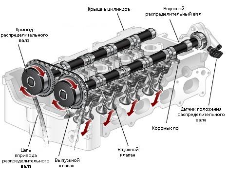
To achieve this accuracy in timing of opening of the intake and exhaust valves, the gas distribution mechanism is synchronized with the engine crankshaft speed. The belt or chain transmits rotation to the camshaft, the cams of which, pressing the rocker arms, alternately open the intake and exhaust timing valves.
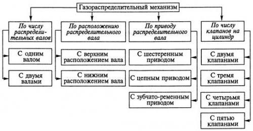
Timing classification
Low valve engines
The gas distribution mechanism of the internal combustion engine passed long way from the 1900s to the present day.
Low valve engines with a camshaft in the cylinder block were used everywhere, until the middle of the twentieth century. The scheme and arrangement of the intake and exhaust valves arranged in a row with the plates facing up, ensured the simplicity of manufacture and low noise of the engine. The main disadvantage of this design was the difficult path of the fuel-air mixture, the suboptimal cylinder filling mode, and, as a result, the lower power power unit.
A gas distribution mechanism of this type was used until the 90s of the twentieth century in trucks. An example of this is GAZ 52, the release of which ended in 1991.
Mixed valve arrangement
Attempts to increase power ICE characteristics led to the creation of an engine with a mixed valve arrangement. The intake ones were in the cylinder head, and the exhaust ones were in the block, like in a conventional "lower valve".
The camshaft is one, also located in the cylinder block. The valves responsible for the intake of the fuel-air mixture were controlled by means of rods - pushers, through which force was transmitted from the camshaft, exhaust - using the usual rocker arm.
Such a layout provided a lower fuel assembly temperature, and, as a consequence, a higher power, in comparison with low-valve internal combustion engines.
Overhead valve engines
The gas distribution mechanism, the intake valves and which are located in the cylinder head, and the camshaft in the block itself, was designed by David Buick at the very beginning of the twentieth century. The valves were controlled by means of rods - pushers, acting on the rocker arms.
Such a layout scheme is highly reliable due to the transmission of rotation from the crankshaft to the camshaft using a gear. A toothed belt worn out during operation can break off, causing serious damage valve mechanism of the timing, a worn out transmission gear will only slightly shift the valve timing, which an experienced driver will notice from changes in engine operation.
The downside is some inertia of such a design, which imposes restrictions on the engine speed, and, consequently, on the torque and the degree of boost. The use of more than two valves per cylinder leads to a more complex gas distribution mechanism and an increase in overall dimensions engine. Four-valve engines of this arrangement are used in KamAZ trucks and diesel locomotive engines.
The gas distribution mechanism of the 21st model Volga car was arranged according to the overhead valve scheme.

- Engines in which the camshaft and timing valves are located in the cylinder head are designated SOHC. The principle of operation and the device of the timing valve control mechanism is very diverse. There is a scheme for opening valves using rocker arms, levers and pushers. Such a device of engines was most widespread in the period from the mid-60s to the end of the 80s of the twentieth century. At the moment, such engines are installed in inexpensive cars.
- Engines with a gas distribution mechanism that includes two camshafts are designated by the abbreviation DOHC. When using two valves per cylinder, each camshaft opens its own series of valves. Such a timing device allows you to reduce the inertia of the crankshaft, and thereby significantly increases the speed and internal combustion engine power... The principle of operation of an engine that uses four or more valves per cylinder is no different from the above. Such power units demonstrate more power than their two-valve counterparts and are installed on most modern cars.

In engines with this type of gas distribution mechanism, the camshaft drive device plays an important role. The transmission element is a chain located in a hermetically sealed volume and washed with oil, or a toothed belt located on the outside of the engine.
Timing drive failure often leads to dire consequences. A broken belt, worn out during operation, causes an instantaneous stop of the camshaft, as a result of which some valves remain open. The piston hitting the protruding plate causes serious damage to the cylinder head. In especially severe cases, repair is impossible and replacement of this engine element is required.
The device of the desmodromic gas distribution mechanism
For engines whose timing design allows the use of springs to close the valves, there is a limitation on the maximum number of revolutions per minute. When the value reaches 9000 rpm, the springs will not be able to provide the desired response speed, which will inevitably lead to engine damage.
The principle of the desmodromic timing is to use two camshafts, one of which opens and the other closes the valves. In such an engine there is no restriction on the developed speed, because the speed of the mechanism's response directly depends on the speed of rotation of the crankshaft.
The creation of a variable-phase gas distribution mechanism became possible relatively recently, with the beginning of its use in engine building. on-board computers and electronic control units. The system of solenoid valves, which changes the operating mode according to the commands of the microprocessor, allows the power to be removed from the engine, approaching the design one, with a minimum fuel consumption.
Do-it-yourself timing belt replacement
Removing the worn out belt and installing a new one in its place, it is easy to change the relative position of the crankshaft and camshafts. In this case, the valve timing of the engine will shift, which will lead to malfunctions, up to and including breakdown. The marks on the gears of the drive mechanism are used for visual control of the timing setting.
Having removed the unusable belt, it is necessary to align the marks of the crankshaft and camshaft gears with the slots in the drive mechanism casing. The purpose of this operation is to set a conditional "zero", from which the engine will start working. Next, you should carefully install the spare belt, being careful not to displace the marks on the gears.
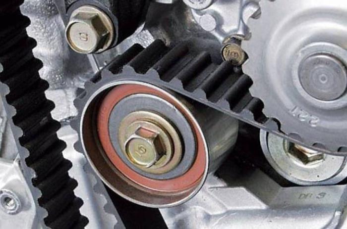
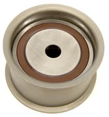
The next step is to inspect and adjust the tension of the idler roller. The purpose of this assembly is to hold the belt on the gears of the drive mechanism. Correct roller adjustment can be checked by turning tensioned belt fingers. If you can crank it ninety degrees, the tensioning mechanism is well adjusted. If the belt turns at an angle less than 90 degrees, then it will be overtightened, if by a larger one, then it will not be tight.
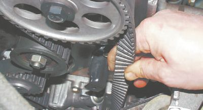
It is very important not to grip the timing belt with oiled hands during installation. This can lead to overshoot on the gears of the drive mechanism.
A belt purchased at a roadside gas station should be carefully inspected. If the storage conditions are violated, even a new timing belt will crack and cannot be used for its intended purpose.
Video illustrating the work of the timing
The gas distribution mechanism is designed for the timely admission of air (diesel engines) or a combustible mixture (carburetor and gas engines) into the cylinders and the release of exhaust gases from them. The gas distribution mechanism can have an upper valve arrangement (in the cylinder head) or a lower one (in the cylinder block). In modern car engines they use a gas distribution mechanism with an overhead valve arrangement, which makes it possible to obtain a compact combustion chamber, to provide better filling of the cylinders with a combustible mixture and to facilitate the adjustment of thermal clearances.
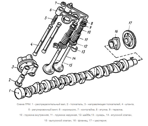
Gas distribution mechanism:
1 - camshaft gear, 2 - thrust flange, 3 - spacer ring, 4 - bearing journals,
5 - drive eccentric fuel pump, 6 - exhaust cams, 7 - intake cams,
8 - bushings, 9 - inlet valve, 10 - guide bush, 11 - thrust washer, 12 - spring,
13 - rocker arm axis, 14 - rocker arm, 15 - adjusting screw, 16 - rocker arm axis,
17 - exhaust valve turning mechanism, I8 - exhaust valve, 19 - rod, 20 - pushers,
21 - gear wheel of the drive of the oil pump and the breaker-distributor
Overhead valve timing.
The figure shows the gas distribution mechanism of the ZIL-130 engine. The force from the cams 6 and 7 of the camshaft through pushers 20, rods 19 and rocker arms 14 is transmitted to the valves, which open by compressing the springs 12. The valves are closed by the action of compressed springs. Common to both banks of cylinders camshaft there are also gears 21 of the drive of the oil pump and the interrupter-distributor, as well as the eccentric 5 of the drive of the fuel supply pump. The camshaft is located in the cylinder block and gear 1 is driven from the crankshaft; the camshaft speed must be half the crankshaft speed.
To limit the axial movements of the camshaft between the gear 1 and the front support journal 4, a spacer ring 3 is installed, which provides a gap (0.1 - 0.2 mm) between the thrust flange 2 and the gear 1.
The gas distribution mechanism of the KamAZ-740 diesel also has one camshaft 1 with a drive gear 17 mounted at the rear end of the shaft.

1 - camshaft, 2 - pusher, 3 - guide pushers, 4 - rod,
5 - adjusting screw, 6 - rocker arm, 7 - lock nut, 8 - bushing, 9 - plate,
10 - inner spring, 11 - outer spring, 12 - washer, 13 - cracker, 14 - inlet valve,
15 - outlet valve, 16 - flange, 17 - gear.
The steel camshaft is mounted in the camber of the cylinder block on five plain bearings.
The axial movement of the shaft is limited by the housing of the rear bearing, against the ends of which the hub of the gear 17 abuts on one side, and on the other - the thrust bead of the rear bearing journal of the shaft.
Steel pushers 2 mushroom type hollow with a cylindrical guide part. The pusher plate has a bleached cast iron cladding.
The guide of the 3 pushers is removable, common for the 4 pushers, which makes it easier to repair. The inlet 14 and outlet 15 valves are made of heat-resistant steel. The valve stems are coated with graphite at a length of 120 mm from the upper end for better running-in. During engine operation, the valves rotate relative to the seat due to the special design of the detachable connection (sleeve 8 - plate 9), which increases the duration of their operation without repair.
In modern high-speed VAZ and Moskvich passenger car engines, the camshaft is mounted on the cylinder head, which simplifies the kinematic connection between cams and valves. This arrangement of the camshaft is called the upper one, it allows to simplify the cylinder block and reduce the noise during the operation of the gas distribution mechanism. On top, the camshaft is driven by a chain or a toothed belt.
Overhead camshaft timing drive:
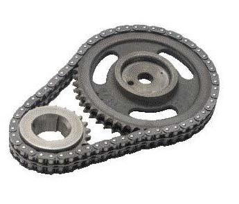
a - chain, b - toothed belt; 1 - crankshaft, 2 - drive sprocket, 3 - chain,
4 - tensioner shoe, 5 - tensioner, 6 - driven sprocket,
7 - camshaft, 8 - valve drive lever, 9 - valves,
10 - adjusting bolt bushing, 11 - adjusting bolt, 12 - chain damper,
13 - sprocket of the drive of the oil pump and the breaker-distributor,
14, 16, 17 - toothed pulleys, 15 - toothed belt, 18 - bolt
For example, on the engines of VAZ-2101 "Zhiguli" cars (Fig. A), the cast-iron camshaft 7 is located in five supports, the aluminum body of which is mounted on studs and is attracted from above to the cylinder head with nuts.
The camshaft cams act on the levers 8, which, turning on the spherical head of the adjusting bolt 11, press the other end on the valve stem and open it. The adjusting bolt is screwed into the cylinder head bushing 10 and locked with a lock nut. The valve is closed by two springs. Rotation from the crankshaft 1 to the camshaft 7 is transmitted by the sleeve-roller chain 3. The same chain drives the driven sprocket 13 of the oil pump drive and the ignition distributor. To reduce the vibrations of the chain, a damper 12, fixed at the end of the engine, serves. To tension the chain, a tensioner 5 with a shoe 4 is provided.
The camshaft drive in the engine of the VAZ-2105 car is carried out by a toothed belt. To do this, on the crankshaft and camshafts(Fig. b) pulleys 14 and 16 with external teeth of a special profile are installed. The pulleys 14 and 16 are enclosed by a belt 15, on the inner surface of which there are also teeth. The belt also covers toothed pulley 17 drive oil pump. The belt is made of special rubber reinforced with a glass cord, and its working toothed surface is covered with a special elastic fabric.
In the design of the drive, a tensioning device is provided, which consists of a smooth roller fixed on the swivel plate, which is pressed against the outer surface of the belt 15 by a spring. To make the belt tension normal, it is enough to loosen the bolt 18 passing through the slot in the plate. This will allow the spring to tighten the plate along with the roller 5, after which the bolt 18 should be tightened.
The entire camshaft drive does not need lubrication; protected from dust and dirt with light plastic covers. The drive by a toothed belt allows (in comparison with a chain one) to reduce the metal consumption and the noise of the gas distribution mechanism.
Cam and bearing journal surfaces camshaft diesel engines KamAZ-740 are cemented and hardened by high-frequency currents. The bearing bushings are made of bimetallic tape and are pressed into the block baffles. The camshaft drive gears are located at the rear end of the cylinder block.
There are four cams between each pair of bearing journals of the shaft - for the valves of one cylinder in the right row and one cylinder in the left row. The angles of the relative position of the cams depend on the order of operation of the cylinders and the valve timing.
Each cylinder has one intake valve and one exhaust valve. For some engines, the camshafts are made of cast iron, in which case their cams and journals are bleached.
Camshaft gears carburetor engines made of cast iron or PCB. The teeth of the gears are oblique, which causes the appearance of a force that tends to move the camshaft in the axial direction.
Pushers made of steel or cast iron. Steel pushers have a welded cast-iron heel in contact with the cam. Pushers are cylindrical, mushroom or roller. The pushers have recesses into which the lower ends of the rods enter. The pushers move in the guides made in the cylinder block, or in the guide housings screwed to it.
Barbells made of hollow steel or duralumin with steel spherical tips, with which the rod rests on one side of the pusher, and on the other, on the spherical surface of the adjusting screw.
Rocker made of steel or cast iron. The rocker arm is longer on the valve side than on the push rod side. This allows the lifting height of the pusher and boom to be reduced. A bronze bushing is pressed into the rocker arm hole. The rocker arms are installed on hollow axes, which are common to all cylinders or are performed separately for each cylinder.
Valves open and close the inlet and outlet ports. The valve consists of a flat poppet head and a stem. The diameter of the intake valve head is larger than that of the exhaust valve. The intake valves are made of chromium steel; exhaust valves (or their heads) are made of heat-resistant steel. Plug-in valve seats, pressed into the cylinder head or block, are made of heat-resistant cast iron. A heat-resistant alloy is sometimes deposited on the working surface of the exhaust valve head. For better cooling, the inner cavity of some exhaust valves is filled with metallic sodium, which has a high thermal conductivity and a melting point of 98 ° C. When the valve moves, molten sodium, moving inside the rod, removes heat from the head to the rod, which is then transferred to the guide sleeve 10.
The working surface of the valve head (chamfer) usually has an angle of 45 °; only for the intake valves of the ZIL-130 engine, this angle is 30 °. The chamfer of the valve head is carefully machined and rubbed against the seat.
The valve stem has a groove into which crackers 7 are inserted to fasten the thrust washer 6 of the valve spring. Valve stems move in guide bushings 10 - cast iron or sintered metal.
The valve is pressed against the seat by one or two springs. With two springs, the direction of their coils must be different so that if one of them breaks, its coils cannot get between the coils of the other.

a - outlet valve, b - valve closed, c - valve open, d - mechanism parts;
1 - body of the turning mechanism, 2 - balls, 3 - support washer, 4 - lock ring, 5 - valve spring,
6 - spring thrust washer, 7 - crackers, 8 - disc spring, 9 - return spring,
10 - guide sleeve, 11 - metallic sodium
The exhaust valves of the engines are forced to turn during operation, which prevents them from sticking and burning. The swing mechanism consists of a stationary body 1 (Fig. A-d), five balls 2 with return springs 9, a disk spring 8 and a support washer 3 with a lock ring 4. The body 1 is installed on the valve guide sleeve 10 in the recess of the cylinder head and has sector grooves for balls 2. Support washer 3 and disk spring 8 with a gap are put on the body protrusion. With the valve closed (Fig. B), when the force of its spring 5 is small, the disk spring 8 is bent with its outer edge upwards, and with its inner edge rests on the shoulder of the body /. When the valve is opened, the force of its spring 5 increases, the disc spring 8 straightens and rests on the balls 2 (Fig. C). The force of the spring 8 is transmitted to the balls 2, and they, rolling along the sector grooves of the housing, turn the disk spring and the support washer, and, consequently, the valve spring and the valve.
When the valve is closed, the force of its spring decreases, the disc spring 8 bends and abuts against the shoulder of the body, releasing the balls 2, which, under the action of the spring 9, return to their original position.
To prevent oil from entering the cylinder along the gap between the valve stem and the guide sleeve 2, a rubber seal in the form of a cap 1 or an oil seal 3 is installed on it or the valve stem.

a - ZMZ-24, b - VAZ-2105;
1 - cap, 2 - guide bush, 3 - oil seal, 4 - labyrinth seal
At present, the so-called four-valve design is increasingly being used abroad (primarily for passenger car engines), that is, the installation of two intake and two exhaust valves in each cylinder. This makes it possible to improve the filling of the cylinders with a fresh mixture, which means to increase the liter engine power (up to 50 kW / l). The spark plug in four-valve carburetor engines is located in the center of the chamber, which shortens the combustion time of the mixture and improves the fuel efficiency of the engine.
Valve timing and cylinder operation
Gas distribution phases.
The valve timing is understood to mean the moments of the beginning of the opening and the end of the closing of the valves, expressed in degrees of the angle of rotation of the crankshaft relative to the dead points. For better cleaning of cylinders from exhaust gases, the exhaust valve should open before the piston reaches BDC, and close after TDC. In order to better fill the cylinders with the mixture, the inlet valve should open before the piston reaches TDC, and close after passing the BDC. The period during which both valves (intake and exhaust) are simultaneously open is called valve overlap.
The valve timing is selected in factories empirically, depending on the speed of the engine and the design of its intake and exhaust systems. At the same time, they tend to use the oscillatory motion of gases in the intake and exhaust systems in such a way that by the end of the closing of the intake valve, there would be a pressure wave in front of it, and by the end of the closing of the exhaust valve, there would be a vacuum wave behind it. With such a selection of valve timing, it is possible to simultaneously improve the filling of the cylinders with a fresh mixture and cleaning them from exhaust gases.
Plants indicate the valve timing for their engines or in the form of diagrams. The diagram shows that the inlet valve starts to open 10 ° before TDC and stops closing 46 ° after BDC. The outlet valve begins to open 66 ° before TDC and stops closing 10 ° after TDC. The overlap of the valves in this case is 20 °.

1 - inlet, 2 - outlet
The correctness of the installation of the TDC timing mechanism is determined by the engagement of the timing gears with the marks on them. A deviation in the installation of the valve timing by at least two teeth of the gear or camshaft sprocket leads to the impact of the valve on the piston, loss of compression, failure of the valve or engine.
The constancy of the valve timing is maintained only if the thermal gap in the valve mechanism. An increase in this clearance leads to a decrease in the duration of the valve opening, and vice versa.
The order of the cylinders.
The sequence of alternating strokes of the same name in different cylinders is called the order of operation of the engine cylinders. The order of work depends on the location of the cylinders, the location of the crankshaft journals and camshaft cams.
In a four-stroke four-cylinder in-line engine, the strokes alternate at 180 °, the operating order can be 1-3-4-2 (Moskvich-2140, VAZ-2106 Zhiguli) or 1-2-4-3 (GAZ-24 Volga ").
In V-shaped eight-cylinder four-stroke engines, the connecting rod journals are located at a 90 ° angle. The angle between the two cylinder banks is also 90 °. When the piston of one cylinder is at any dead center, the piston of the adjacent cylinder is approximately in the middle of its stroke. Therefore, the strokes occurring in the left row of cylinders are displaced relative to the corresponding strokes occurring in the cylinders of the right row by 90 °, or 1/4 of a revolution, of the crankshaft.
- to the begining -
V passenger car the engine will not be able to function properly without a clear and well-coordinated timing. He is responsible for the timely injection of fuel into the cylinders, and also removes the exhaust gas from the system. Another one important feature- timing marks. It is necessary to strictly observe them, otherwise the injection and release of gases will go astray.
This device has a complex design. The timing belt consists of the following parts and mechanisms: drive elements, a camshaft and a timing gear, valve drive elements, the valve itself and springs, as well as guide bushings. The gas distribution mechanism is synchronized with ignition and injection.
Camshaft
The job of the camshaft is to open the valves in the order required for the engine to function properly. For the production of these parts, cast iron or special steel is used. To reduce wear on the part, its surfaces are hardened using high frequency current, while they are heated.
 There are two places where the camshaft can be located. This is either the crankcase or the cylinder head. There are also engine options when there are two camshafts in the head at once (multi-valve internal combustion engines). The camshaft rotates on special bearing journals.
Classification of engines depending on the number of camshafts
Depending on the number of camshafts, engines are divided into double (DOHC - Double Overhead Camshaft) and single (SOHC - Single Overhead Camshaft). If we consider a DOHC type engine, then there one camshaft controls the intake valves, and the other controls the exhaust valves. At SOHC, these functions are performed by a single camshaft.
The valves are driven by cams that are attached to the camshaft. Their number directly depends on the number of valves. Depending on the design of the engine, it can vary from two to five per cylinder. There are various valve configurations: two inlet and one outlet, two of each type, three inlet and two outlet. The shape of the cams is responsible for how exactly the valve will open and close, the time of its opening and the lift height.
Camshaft drive: general information
The camshaft can be driven from the crankshaft in three different ways: by a belt (belt drive), a chain (chain drive), and if the engine is configured with a lower camshaft, then by means of toothed gears. It is the chain drive that is rightfully considered the most reliable, but it is distinguished by its complex design and high price. The belt drive is much simpler, but the service life of its belt is lower, and if it breaks, the consequences can be dire.
If the belt breaks, then the camshaft stops, and the crankshaft continues to run. What does this threaten? If the engine is multi-valve, then during operation the pistons will hit the valves, which remain open. This can not only damage the rods, but also the guide bushings. The piston itself may even collapse. In simple two-valve engines, there is no such problem, so repairs there are limited to just replacing the belt.
If the timing belt breaks by diesel engine, then the consequences will be even more severe than on gasoline. Since the combustion chamber is located in the pistons, there is very little room for the valves. So if the valve hangs in the open position, then only the rods and bushings are destroyed, but also the camshaft, bearings, pushers, there is a high chance of deformation of the connecting rods. And if the belt breaks off at high revs you could even damage the cylinder block.
Gas distribution mechanism drive: varieties
Depending on the location of the camshaft, there are several types of timing drive. If the camshaft has a bottom position, then the force is transmitted to the valves using pushers, rods and rocker arms. If the camshaft is at the top, there are three options for the drive: rocker arms, pushers and levers.
Rocker arms are also called rockers or roller levers, they are made of steel, mounted on an axle that is mounted on the racks in the cylinder head. The rocker arms rest against the camshaft cams, and also act on the end of the valve stem. In order to reduce friction during their operation, a special sleeve is pressed into the hole.
If the camshaft is located above the valves, then they are driven by means of levers. The camshaft cams act on the valve stem. There are varieties of timing, in which a hydraulic compensator is placed between the lever and the valve. Such instances do not require clearance adjustment.
In the third version, the camshaft acts directly on the valve tappet itself. Pushers are mechanical, hydraulic and roller. The former are practically not used, since they are too noisy, and also require adjustment of the gap. The most popular is the second type, since the hydraulic pushers do not require such adjustment and are much quieter. They operate on the basis of engine oil, it constantly fills the internal cavities and thus displaces the piston when a gap appears.
Roller tappets are often used in uprated engines because they improve dynamics by reducing friction. The thing is that when interacting, the cam rolls along the pusher, and does not rub, since the roller is located in that place.
Valves
Valve distribution is most widely used due to its simplicity and high reliability. It allows you to most effectively implement the purpose of the gas distribution mechanism.
The valve's job is to open the intake and exhaust ports at a specific time. The valve itself has a fairly simple structure - a head and a stem. The valve heads have different diameters for intake and exhaust valves. Since the exhaust heats up much more during operation (since they come into contact with heated exhaust gases), they are made of heat-resistant steel.
On the rods in the upper part there is a groove for fixing the valve spring parts. They themselves are made hollow, filled with sodium (better cooling is provided). The rods are fixed in bushings, which are made of cermet or cast iron. The bushings, in turn, are pressed into the cylinder heads.
Possible faults in the timing
Since the gas distribution mechanism consists of a large number of parts, it would be logical to assume that there is a high risk of breakage. Among the most common reasons are the following:
Wear of bearings or valve tappets - can be determined by increased motor noise;
Problems with hydraulic lifters - manifested in the form of a knock when the engine is running;
Burnout of valves or formation of carbon deposits in the system;
Worn valve seals - oil enters the system and begins to burn in the cylinders;
Wear of the timing belt or chain - the engine power drops, it makes noise, there are malfunctions in the phases of operation.

It is worth saying that on modern cars the timing is made quite high quality, this significantly increases its operational life. After all, if, for example, you take the VAZ 2106 gas distribution mechanism, you can see that it needed constant maintenance, valve adjustment and replacement of certain parts.
Signs by which you can determine that the gas distribution mechanism is faulty are extraneous sounds in the exhaust and intake pipes (pops or noise), a decrease in compression, a metallic knock, or a drop in engine power. The appearance of these signs signals that the timing belt is faulty and needs to be repaired.
Duty cycle of the engine and timing
According to the standard, the working cycle of the internal combustion engine is carried out in 2 crankshaft turns. During this period of time, the valves of each cylinder must open and close in a certain sequence. Therefore, the camshaft always rotates slower than the crankshaft. Accordingly, the sizes of the gears of these shafts are different (the camshaft has a larger one). The valves open depending on the direction and movement of the cylinders in the engine. That is, during the intake stroke, the intake valves are open, and vice versa - during exhaust, they are closed. It is for this purpose that timing marks are applied to the gears.
Gas distribution phases
The theory says that the valves should open when the cylinders pass through the dead center. But since the process is inertial, and also when taking into account the increased crankshaft speed, this time is clearly not enough for the injection of the mixture and the release of exhaust gases. Therefore, the intake valve opens even before the cylinder reaches the top dead center position (with a lead of approximately 9-24 degrees of crankshaft rotation), and closes while the cylinder passes the bottom dead center (51-64 degrees lead).
The exhaust valve opens approximately 44-57 degrees before the cylinder reaches the bottom dead center position. It closes at about 13-27 degrees of its passage by the cylinder.
During engine operation, there are times when both valves are open. This position is intended for purging the cylinders with a fresh combustible mixture in order to clean them of excess combustion products. This is called valve overlap.
The moments when the valve opens or closes relative to the dead points are called valve timing, they are calculated in degrees of crankshaft rotation.
Naturally, such an important part of the car as the timing belt simply will not tolerate careless handling. Of course, the engine's gas distribution mechanism is a fairly reliable unit, but even it can be completely broken. Poor-quality repairs can be one of the reasons for breakdowns. Therefore, you should pay close attention to this.
What do you need to know?
The first thing you need to know before repairing the gas distribution mechanism with your own hands is that it is very difficult to perform it. This requires technical skills that the average motorist is unlikely to have. Also, certain tools will be needed, which can not be found in every garage. And any careless movement can cause consequences that will turn out to be much worse than the initial breakdown. Therefore, you should always entrust the repair of your car's timing belt only to trusted specialists.
The design of the gas distribution mechanism is such that most often during its operation moving parts fail: valves, cams, camshaft. If the damage or malfunction is not critical, it is quite possible to do without replacing any parts. But if they are serious, you need to be ready to spend money on buying and installing new parts. A certain amount will also have to be paid for the repair procedure itself.
Like any other technique, a car can work for a long time and trouble-free if it is used correctly. Conversely, careless handling will only increase the chance of breakage.
The gas distribution mechanism is one of the most important parts, without which the engine cannot function. Therefore, taking care of him is a factor that should not be overlooked.
How to protect the timing from damage?
First, you should always use only high quality fuel. If it is with foreign impurities, the valve outlets may become clogged, the engine will interrupt. The same applies to components - defective parts will not work for a long time and will only cause harm. So you should always choose only the best parts and consumables for your car.
An equally important factor is correct operation... You should not expose the car to overloads that will be harmful to it. Overheating of the engine, work with faulty components, long-term operation without maintenance will reduce the life of the machine and destroy its components and assemblies. Therefore, the rules for operating a car should not be neglected either.
The camshaft is an axle with cams machined on it. The cams are located along the shaft so that in the process of rotation, in contact with the valve pushers, they are pressed exactly in accordance with.
There are engines with two camshafts (DOHC) and a large number of valves. As in the first case, the pulleys are driven by one timing belt and chain. Each camshaft closes one type of intake or exhaust valve.
The valve is pressed by a rocker arm (early versions of engines) or a pusher. Distinguish two types of pushers... The first is the pushers, where the gap is adjusted by the calibration washers, the second is the hydraulic pushers. The hydraulic pusher softens the impact on the valve thanks to the oil in it. No cam-to-follower clearance adjustment is required.
The principle of operation of the timing
The whole gas distribution process is reduced to the synchronous rotation of the crankshaft and camshaft. As well as opening the intake and exhaust valves at a certain point in the position of the pistons.
To accurately position the camshaft relative to the crankshaft, alignment marks... Before putting on the belt gas distribution mechanism the marks are combined and fixed. Then the belt is put on, the pulleys are "freed", after which the belt is tensioned with tension (s) rollers.
When the valve is opened with the rocker arm, the following occurs: the camshaft with a cam "runs over" the rocker arm, which presses the valve, after passing the cam, the valve closes under the action of a spring. The valves in this case are arranged in a v-shape.
If pushers are used in the engine, then the camshaft is located directly above the pushers, when rotating, pressing with its cams on them. The advantage of such a timing belt is low noise, low price, maintainability.
In a chain engine, the entire timing process is the same, only when assembling the mechanism, the chain is put on the shaft together with the pulley.
In other words, at the moment of pressing the gas pedal, the driver opens throttle, which means more air flow into the intake manifold. More air results in more air / fuel mixture. The task of the timing belt is to immediately increase the throughput for better filling of the combustion chamber and further release of exhaust gases. This requires an increase in the frequency of opening and closing.
The timing drive is directly implemented from the engine. The engine valves are actuated camshaft... It turns out that an increase in the crankshaft speed makes it rotate faster, which increases the frequency of opening and closing the valves. The result is an increase in engine speed and an increase in the return from the power unit. The interrelation of the camshaft and crankshaft allows the internal combustion engine to efficiently obtain and burn the fuel-air mixture in the amount necessary for a particular mode of engine operation.
Evolution: upper and lower valve arrangement
The internal combustion engine in the process of evolution received a low-valve and an overhead valve arrangement of valves. The lower valve engine is an internal combustion engine with a lower valve arrangement. The bottom valve design of the engine is with the valve disc pointing upwards. The valves are inverted and are not located on top of the engine cylinder, but on the side. Motors with a low-valve circuit received the abbreviation SV (English side-valve), which means "side valve".
The main difference between SV type motors is the relative simplicity of the lower valve engine compared to OHV, SOHC, DOHC, etc. The disadvantages include the low efficiency of filling the combustion chamber with a fuel-air mixture. This means that the LV engine is less efficient and potentially has less boost. The second serious drawback was the obvious tendency of motors of this type to overheat.
Low-valve engines were widespread on civil cars and other equipment until the middle of the 20th century, although from the very beginning of the era of engine building they were highly accelerated racing cars received more advanced schemes for the device of the gas distribution mechanism.
Today, the vast majority of ICEs are equipped with overhead valve timing mechanisms. This layout quickly supplanted the under-valve design in the 60s, when engine power became a priority for engineers. The overhead valve timing made it possible to get rid of many additional parts that are structurally necessary for the implementation of the lower valve circuit. The overhead arrangement allowed the camshaft cams to directly and without loss press on the valve stems. Sustainable ICE operation at maximum revs, efficient cylinder filling and increased power are the result of the use of an overhead valve circuit.
The overhead valve arrangement significantly simplified the repair and maintenance of the power unit. Placing the camshaft on top of the engine made it possible to reduce the total weight, noise and vibration levels during the operation of the power unit. Moreover, the overhead valve design allowed the timing and the engine to evolve further, since it became possible to increase the number of valves per cylinder (today, motors can have 8.16, 24 or more valves). It also became possible to implement the installation of not one, but two camshafts at once (one shaft for the intake, and the other shaft for the exhaust valves). The main disadvantage of the overhead valve design is considered to be a chain or belt valve drive system.
Gas distribution mechanism device
The gas distribution mechanism consists of a number constituent elements that perform the following functions:
- the camshaft drive mechanism rotates the shaft at the desired speed;
- the camshaft opens and closes the valves;
- valves open and close the inlet and outlet channels;
The basis of the entire timing is the valves and the camshaft (camshaft). The camshaft is an element on which so-called cams are made. The camshaft rotates freely on bearings. During the rotation of the camshaft, these cams press on the valve lifters at the very moment when an intake or exhaust stroke occurs in the engine cylinder.
The gas distribution mechanism is partially located in the upper area of the engine block. The place of installation has become. The head contains the camshaft and its bearings, the valves themselves, rocker arms or valve lifters. The top of the head is covered by a valve cover. This valve cover is fitted to the cylinder head using a special gasket.
Timing belt and chain: drive features
The camshaft drive pulley is removed from the cylinder head. To prevent oil leaks, the camshaft journal has an oil seal. The timing mechanism is driven by a belt or chain. The timing chain or timing belt slides over the camshaft pulley or driven sprocket on one side, and on the other side, the force is transmitted from the crankshaft gear.
The chain or belt drive of the valves provides the most important requirement - the constant position of the crankshaft and camshaft (or several shafts) in relation to each other. Even the slightest deviation will lead to a lack of synchronization and engine malfunctions. More serious violations immediately manifest themselves in the form of serious damage to the internal combustion engine.
Chain transmission using a roller chain is considered more reliable, but there are certain difficulties in ensuring the required tension. The main disadvantage of the timing belt is the potential risk of breaking it, which in some cases leads to bending of the valves.
The list of additional elements also contains tensioning rollers for tensioning the timing belt; for the chain, a timing chain tensioner (chain "shoe") is used. The disadvantages of the timing chain drive also include increased noise during operation. The disadvantage of the timing belt is the need to replace it every 50-60 thousand km, as well as monitoring the condition of the belt and rollers at regular intervals.
Valve mechanism
 As for the valve train, this includes guide bushings, valve seats, return springs, valve rotation mechanism, and other parts. The camshaft at the right time transfers the force directly to the valve stem (stem) or through an intermediate link - a rocker (valve rocker).
Structurally, there are timing, which require periodic adjustment. The design includes special adjusting bolts and washers for setting permissible clearances... There is also a solution where the required clearance is automatically maintained at all times. The gap adjustment in such mechanisms is carried out by means of hydraulic lifters.
Camshaft timing control
In construction modern engine major changes have taken place in recent years. We are talking about the emergence of control systems based on microprocessors (ECU). Against the background of the constant rise in fuel prices and the tightening of environmental standards, the priority task of engine building has become not only the power of the units, but also the efficiency.
It was possible to reduce fuel consumption and improve the performance of the internal combustion engine without loss of power thanks to the advent of distributed injection and timing control systems. Such variable valve timing systems (English Variable Valve Timing, VVT) have received international recognition and are actively used by leading car manufacturers around the world.
Changing the valve timing (among auto mechanics, this system has received the common name "phase shifter") will make it possible to realize optimal synchronization of intake and exhaust in relation to specific conditions of engine operation at different modes.
The operation of this system is that it controls the speed of rotation of the timing camshafts. The system turns the camshaft slightly in the direction of rotation, allowing the valves to open earlier when needed. This means that in modern motor the camshaft no longer rotates at a constant speed relative to the crankshaft.
The main task is the most efficient filling of the cylinders, depending on the operating mode of the engine. Imagine a car that is moving almost by inertia, although the driver continues to press the accelerator lightly. The system dynamically detects that there is no load on the engine at such moments and adjusts the valve timing. For mode idle move fuel consumption should be minimized, since it makes no sense to supply the working air-fuel mixture in full. VVT system constantly monitors the operation of the power unit and actively controls the rotation of the camshafts.
Further development of such systems led to the emergence of solutions in which the use of camshaft cams of various shapes was noted. Such a scheme made it possible to stepwise change the duration of the opening and the height of the valve lift. This system variable valve timing is the most advanced and is actively developing today, based on the dynamic adjustment of the intake valve lift.