Since AvtoVAZ products are very popular in the vastness of Russia, each domestic manufacturer of on-board computers paid attention to these cars. Moreover, let's face it, it is VAZ that is so "smart" technical tuning will be especially appropriate. You can buy a model VAZ on-board computer, and the fret on-board computer looks especially good on the “tenth” family - computer 2114, computer 2110, computer 2115 (both “Multitronics” and “Gamma” are installed in these models in a regular place). You can pick up trip computer Vaz from universal BC. For example, a computer on Grant can be installed instead of a button. By the way, side vaz appropriate even where there is an analogue of such a device. For example, a computer for Kalina and a computer for Prioru not only shows fuel consumption, like standard devices, but also reminds when to change pads, renew insurance, explain why the "cheсk" light came on and performs dozens of other useful functions that significantly save the car owner's costs in the end. who put the computer on the WHA.
How to choose a VAZ on-board computer
To understand which VAZ on-board computer to buy, you first need to look into your wallet. After all, the section in which you will need to look for your bortovik depends on how much you are ready to spend on the trip computer of the VAZ. Of course, the price of the device varies depending on the type of screen, the number of functions, the ability to work with different types of fuel (gas / petrol). But in general, devices made for a specific model, for example, computer 2114, computer 2110, computer 2115 will be the most economical option. These devices, of course, will fulfill all their main tasks, like an on-board computer. But these computers were developed for VAZ several years ago, and since then they have not been particularly modernized (like the car models themselves). A computer for Grant, a computer for Kalina and an on-board computer for Priora look more presentable and perform more functions. To find the best BC for you, use the section "Selection by car" on our website, indicating the model of your car.
An on-board computer is a special device that provides information useful to the driver and controls the executive systems of the car. The on-board computer is of several types, which should be taken into account in the process of selecting and installing a device. To get the information you need, look at the label (it contains all the data).
When choosing a device, consider the type of engine on the car. This is due to the fact that different types on-board computers, as a rule, are "sharpened" for certain motors. Most in demand today injection engines, therefore, the range of models for them is the widest. Among the existing devices, Multitronics is considered the most versatile and reliable.
Appointment
- the opportunity for the car enthusiast to take control of many of the car's options. At the same time, the functionality and capabilities of modern models meet the needs of the most demanding car owners.At first glance, the on-board computer duplicates the indicators that are already reflected in dashboard car VAZ-2114. For example, the car owner has access to information from the speedometer, which displays the speed of movement, clock and tachometer (shows the crankshaft speed). In addition, the odometer information about the distance traveled is in front of your eyes.
The devices mentioned above are located on the dashboard, and the data they give out is easy to read. But even that is not all. The car owner also receives other information - the amount of fuel remaining in the tank, the air temperature (inside and outside) and others. Manufacturers are attentive to the organization of the functional part, so the driver has access to all the data necessary during the driving process.
Why then do you need to connect an on-board computer?
The purpose of the device is to expand the capabilities of the car owner and provide additional information... At the same time, the indicators are not only collected and transmitted to the screen - they are processed, which guarantees an accurate assessment of the condition of the car, at a specific point in time.
What is the difference between an on-board computer and an already installed control panel?
Experienced car owners know that the standard speedometer can be easily fooled. When issuing information, the device takes into account the crankshaft speed and wheel revolutions. If you put large discs or rubber, thereby increasing the diameter, then the speed will rise. In this case, the indicator will continue in the same mode.
Installation of an on-board computer - the ability to obtain accurate data, eliminate problems with the traffic police and fines due to incorrect display of speed. An additional device also records a number of other useful parameters - averaged and real expense fuel, total and current mileage, the amount of fuel consumed in one trip (from the moment the engine was started), and so on. Most of the parameters, as a rule, can be calculated in the head using information from a classic dashboard. The downside is that it will take time. And on the road, you need to engage in driving, not calculations.
Connecting an on-board computer to the VAZ-2114 opens up many possibilities:
- The device monitors the temperature of the engine and warns of possible overheating.
- More advanced devices signal ice formation and advise you to take your time.
- Many models inform about the voltage level in on-board network, engine operating parameters, travel speed and give out a number of other important information.
All that remains for the car owner is to listen to the signals of the on-board computer and respond to them in a timely manner.
On the one hand, a powerful indicator appears in the car that collects and provides the most important data to the driver. On the other hand, a lot of information is already known, but the only difference is that it is not displayed to the driver. Why then install an on-board computer? In a practical sense, this device is irreplaceable. It collects as much information as possible from the sensors, then processes it, decrypts and submits it in a form convenient for the driver. At the same time, the car owner does not need to make independent calculations - everything is monitored by a special on-board computer, which warns about the problem in time.
How to connect the device?
The manufacturers of the VAZ-2114 car have provided a special block to which the on-board computer is connected. This feature speeds up and simplifies the process. So, to the provided connector, you can connect devices from the manufacturers "State" or "Multitronics". Drivers who have already tried the capabilities of on-board computers, as well as experts in this field, recommend these particular devices.

Optionally, you can choose a model with a color display. But this option is more "for an amateur". The presence of such an option does not affect the functionality, and the add-on itself is made "for beauty".
On-board computer installation process
- Connect the device to power. This will require a voltage of +12 Volts of the on-board network of the VAZ-2114.
- To automatically start the device (together with turning on the ignition), use the wire used to start the engine. If you connect the on-board computer to a "size" power supply, then, when darkness falls, the screen brightness will decrease.
- Connect the ground wire.
If desired, you can bring in information from a sensor that monitors the fuel level. But here a lot depends on the device model. In some on-board computers, when setting the correct parameters (mileage and fuel consumption), the calculation is carried out automatically. This process is called calibration.
At the end of the work, switch the diagnostic line of the "K-Line" controller.
How to connect when there is no shoe?
The situation is more complicated when a special shoe is not provided in the car. As a rule, it is enough to connect a special 4-pin connector with adapters (often provided for cars).
If there is no such block, then connecting the on-board computer should also not cause problems. +12 Volt power can be taken from the cigarette lighter socket, and to ensure self-start - from the ignition switch. To ensure dimming, when turning on the dimensions, take the wire from the backlight of the cigarette lighter. There are no problems with the "mass" - take it from the casing or all the same cigarette lighter socket.
To exclude problems during the installation of the on-board computer and its settings, it is advisable to disconnect the "ground" with the battery in advance.
The signal from the sensor that monitors the fuel level is easy to find after examining the electrical wiring of the VAZ car. At the same stage, find the K-line of the diagnosis. In addition, all the necessary information is already available in the instructions for the on-board computer, so there should be no problems with the connection.
If the device was inherited from the previous owner or as a gift, and there is no information for it, then the necessary data is easy to find on the Internet - just go to the search engine and enter the model name into the search line. Most often, the models sold on the market are standard, and the instructions for them are identical.
The presence of an on-board computer is an opportunity for the car owner to always be aware of the events taking place in the electrical and power parts of the car. At the same time, unpleasant surprises are excluded. If you do not want to spend money on an additional device, you can go the other way - periodically monitor the state of the car systems yourself or contact the specialists at the service station.
A little dream came true, I bought myself a bortovik that I dreamed of from the first car) Now find it so rare with us, I saw the ad and took it on the same day) How happy the child was when he installed it)) And so that he would sit straight, not hang out I glued it with an antiskrip, there is just a bunch of it left)) For one thing, and there will be no noise)
I also throw in the diagram for connecting the bortovik state 2114:
Bortovik functions:
How I was tortured to turn off the alarm clock on it, which was always beeping, but then I figured it out, it turned out to be difficult to find instructions, but I will provide you in this post :) In the future I plan to overexpose the bortovik, otherwise an annoying green light))
Instructions
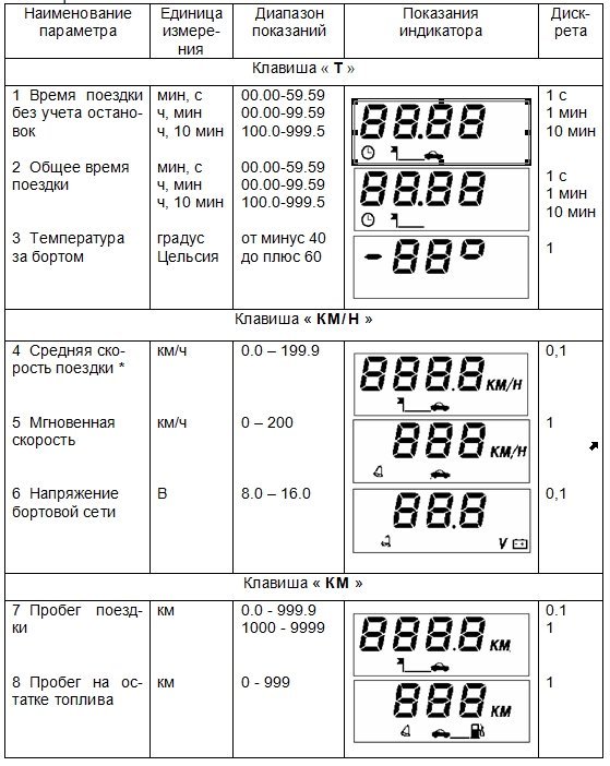
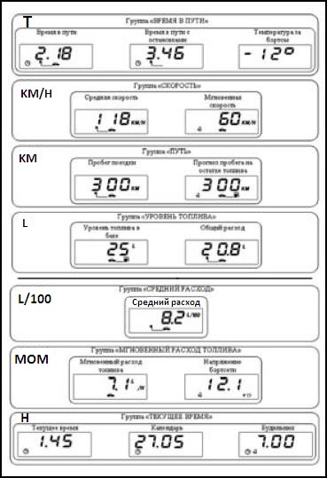
Trip computer (MC), installed on some of the manufactured LADA cars SAMARA. MK has
15 functions divided into 7 groups. Seven control buttons are used to select the desired group of functions and
selection of functions within the group and have the following designation: “T”, “KM / N”, “KM”, “L”, “L / 100”, “MOM”, “N”.
Functions within the group are looped over. When the ignition is off, the computer is always in the “Timekeeping” mode, and the button control functions are locked.
Pressing any button, with the ignition off, turns on the night illumination of the indicator, and the “START” button turns off the sound signal of the alarm clock. To reset all accumulated parameters: “Time at
travel ”,“ Travel time with stops ”,“ Total consumption ”,“ Trip mileage ”, press and hold the“ START ”button for more than 4 s until a two-tone sound signal appears.
Indication of the following parameters: “Average speed”, “Average fuel consumption”, “Forecast of mileage on the remaining fuel” is carried out if the following conditions are met: the trip mileage is more than 1 km and the trip time, excluding stops, is more than 1 min; until these conditions are met, “----” appears on the display.
The computer has 3 signaling devices: “Overspeed”, “Mileage on remaining fuel” and “On-board network voltage”. When the monitored parameter goes beyond the set value: maximum speed (20-200) km / h, depending on the setting; mileage on the remaining fuel is less than 50 km; stresses
the on-board network is below 10.8 V or above 14.8 V, the bell symbol starts flashing and a sound signal is generated, while the value of the monitored parameter is displayed on the indicator.
The sound signal is reset with the “START” button. After the sound signal has been reset, the indication of the parameter outside the set value is accompanied by a flashing bell symbol. When the parameter returns to its normal value, the alarm stops.
To set or remove the monitoring mode, select the monitored function and use the “START” button to set or reset the bell symbol. Resetting or setting the sound signal of confirmation of pressing the keys is performed in the mode of the “Travel time” function by pressing the “START” button.
In the “Instantaneous (average) fuel consumption” mode, when the instantaneous (average) speed is less than 5 km / h, the readings are displayed in l / h and in l / 100 km, when more. readings are displayed in minutes, seconds at a time less than an hour, in hours, minutes at a time more than an hour
and in hours at a time of more than 99 hours 59 minutes.
At removed battery the clock rate and all accumulated parameters are saved for at least 1 month.
Adjusting computer functions
Clock drift correction
Press the "START" button in the "Current time" mode. On the sixth signal of the exact time, press the "H" button, while the digits of minutes are reset to zero, the digits of the hours are corrected to the nearest value,
seconds must start at zero.
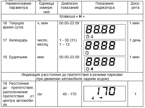
Setting the current time (calendar)
Press the "START" button in the "Current time" ("Calendar") mode. Use the “+”, “-” buttons to set the required hour (day) value. Press the “START” button. Use buttons “+”, “-” to set the required value of minutes (month). Press the “START” button to finish setting the time (calendar).
Setting the alarm
Press the "START" button in the "Alarm" mode. Use the “+”, “-” buttons to set the required hour value. Press the “START” button. Use the “+”, “-” buttons to set the desired value of minutes. Press the “START” button to finish setting the alarm. In the “Time of day” mode, the alarm symbol will light up (the alarm clock is on).
Turn off the alarm
Press the "START" button in the "Alarm" mode. Press the "H" button to turn off the alarm. In digital
digits, “--.--” appears, and in the “Time of day” mode the alarm symbol will not light up (the alarm is turned off).
Adjusting the brightness of the indicator backlight
When the side lights are on, the illumination level is adjusted with the dimmer on the instrument scale. When the side lights are off, the backlight level is adjusted programmatically: Press the “START” button in the “Travel time with stops” mode. The indicator will light up all single segments (pictograms), which is a sign of the level adjustment mode
backlight, and in digital digits the number corresponding to the backlight level as a percentage of the maximum value will be displayed. Use the “+”, “-” buttons to set the required backlight brightness level.
Press the “START” button to end the brightness adjustment mode.
Fuel level sensor calibration
To carry out the correction, it is necessary to drain all the gasoline from the tank. Press and hold the “START” button for more than 2 s in the “Fuel level” mode. A blinking number “0” will appear on the display. Press and hold the "L" button
within 1s until the confirmation beep appears. After that, the indicator will show a blinking number “3”. Pour 3 liters of gasoline into the gas tank using a measuring container, wait the time required for the fuel level sensor to calm down, press and hold the “L” button for 1s until a confirmation beep appears. Continue this procedure to a maximum value of 39 liters, after which the computer automatically exits the mode.
Overspeed alarm installation
Press the “START” button in the “Medium speed” mode. By buttons “+”, “-” set the required speed threshold.
Press the “START” button to exit the overspeed alarm setting.
Accuracy and Limits of Certain Functions
Range of indications of hours. ... ... ... ... ... ... ... ... ... ... ... ... ... ... ... 0 h 00 m – 23 h 59 m
Leaving hours per day at (25 ± 10) ° С, no more. ρ 3 s
Outside temperature reading range. –40 ° С ... + 60 ° С
The maximum travel time. ... ... ... ☺ 999 h 50 m
The maximum travel time with stops. ... ... ... ... ... ☺ 999 h 50 m
The maximum value for the total consumption. ... ... ☺ 9999 l
Maximum value total mileage... ... ... ... ☺ 9999 km
If one of these parameters overflows, all accumulated parameters are reset: “Travel time”, “Travel time with stops”, “Total consumption”, “Trip mileage” with a two-tone sound signal.
AUTOMOTIVE ROUTE COMPUTER AMK-211501 Passport РЮИБ.402253.507-01 PS Automobile route computer АМК-211501 (hereinafter referred to as the computer) is designed to process sensor signals and display vehicle movement parameters, fuel consumption, ambient temperature, on-board network voltage, time parameters, diagnostics electronic systems engine management (hereinafter referred to as ECM), as well as for detecting obstacles and indicating the distance to them when the car is moving in reverse (with a connected car parking device).
We ask you to carefully read this passport, which will allow you to fully use the performance of your computer. When buying, it is necessary to check the absence of external mechanical damage, the completeness, the presence and integrity of the factory seal, the correspondence of the serial number of the computer to the number indicated in this passport, as well as the passport, signed and stamped by the seller. The manufacturer may make minor design changes to the computer that do not impair its quality and reliability, which are not reflected in this passport. on-board computer for vaz 2114 operating instructions Legal address of the manufacturer: Russia, 305038, Kursk, st. 2nd Rabochaya, 23, OJSC "Schetmash".
ATTENTION: THE COMPUTER IS DELIVERED TO THE CONSUMER WITH A PROTECTIVE FILM ON THE GLASS OF THE COMPUTER PANEL, WHICH CAN BE REMOVED AT THE DESIRE OF THE CONSUMER.
1 Product basics and technical data
1.1 The computer is installed on cars VAZ 2108, VAZ 2109, VAZ-21099, VAZ-2115 (hereinafter - VAZ cars) with a carburetor type engine or equipped with an ECM with an electronic control unit (hereinafter - ECU) М1.5.4, М1.5.4N, МР7 .0 or January-5.1, cars GAZ-3110, GAZ-3102 with engines equipped with ECM with ECU: MIKAS 5.4, MIKAS 7.1, 301.3763 000 01. Operating instructions for the on-board computer VAZ 2114 The computer can be installed on other types of cars, providing the receipt of vehicle speed and fuel consumption signals to the computer with the signal parameters given in Appendix A. To ensure the performance of all computer functions, a car with a carburetor type engine must have the following equipment manufactured by OJSC "Schetmash": - fuel consumption sensor TU 4213-001-00225331 -95 (hereinafter referred to as DRT), - vehicle speed sensor TU 4228-001-00225331-95 (hereinafter referred to as DSA), - external temperature sensor TU 4573-028-00225331-00 (hereinafter referred to as DVT), - a set of mounting parts RYUIB.402921.501 LLP (RYUIB.402921.501-02) (hereinafter - KMCH), purchased by the consumer (if necessary) separately. standard on-board computer VAZ 2114 A car with an engine equipped with an ECM must be equipped with a set of mounting parts RYUIB.402921.501 LLP (RYUIB.402921.501-03) (hereinafter referred to as KMCH1) and DVT produced by JSC "Schetmash", to be purchased by the consumer separately. GAZ-3110 car with ECU MIKAS 5.4, MIKAS 7.1, 301.3763 000 01 must be equipped with a set of mounting parts RYUIB.402921.501 LLP (RYUIB.402921.501-06) (hereinafter - KMCH2) produced by OJSC "Schetmash", purchased by the consumer separately. To use the "Parking" function, the car must be additionally equipped with a car parking device RYUIB.453688.501 manufactured by OJSC "Schetmash", purchased by the consumer separately. on-board computer for vaz 2115 instructions
1.2 The computer displays the parameters: - the current time of day; - travel time excluding stops; - total travel time; - calendar; - alarm; - current fuel consumption; - average fuel consumption per trip; - total fuel consumption for the trip; - mileage on the remaining fuel; - fuel level in the tank; - trip mileage; - average travel speed; - temperature overboard; - instantaneous speed; - voltage of the on-board network; - the presence of an obstacle and the distance to it when the vehicle is reversing. The parameters and sequence of switching the display modes of the computer are given in Appendix B. The computer receives and displays diagnostic information from the ECM and performs the following ECU diagnostic functions: - reading fault codes; - reset of all accumulated ECU codes of malfunctions; - reading a set of parameters of the ECU; - reading the identification data of the ECU (the function is not available when selecting ECUs of the type MIKAS 5.4, MIKAS 7.1, 301.3763 000-01). The computer receives information about the distance to an obstacle from the car parking device. The computer provides reception of signals from sensors installed in the car: DSA, DRT, DVT and fuel level sensor (hereinafter FLS). The parameters of the output signals of the sensors are given in Appendix A. The computer is designed to work in a circuit direct current with a rated supply voltage of 12 V DC in accordance with GOST 3940 84. The operating range of the supply voltage is from 10.8 to 15.0 V. The standard on-board computer VAZ 2115 instruction Maximum current consumption of the computer at a supply voltage of 13.5 V and there is no sound signal in the range operating temperatures, A, not more than: - with the ignition off and no backlight voltage at contact "6" ……. ……. …………………………………………………………. 0.015; - when the "backlight" mode is turned on ………. ……………….… ... 0.160. The operating range of the ambient temperature is from minus 40 to plus 60 ° C. dimensions, mm, no more ... ... ... ... ... ... ... ... ... ...... 238х50х56. Weight, kg, not more than ……………………………………… .. …………… ... 0.4.
2 COMPLETE SET
Trip computer AMK 211501 - 1 pc. Route computer AMK 211501. Passport - 1 copy. Packing - 1 pc.
3 DEVICE AND MODES OF OPERATION
3.1 Computer structure
A general view of the front panel of the computer is shown in Figure 1. The computer has a case, on the front of which there is a panel with a liquid crystal indicator (hereinafter referred to as the indicator) and ten keys for controlling the computer. On the rear wall of the case there is a connector for connecting the car's wiring harness. Seven keys are used to select the desired group of functions and select functions within the group and have the following designation: "T", "KM / N", "KM", "L", "L / 100", "ECU", "H". The "START" key is intended to determine the beginning of the trip and reset the accumulated parameters, to fix the parameter value in the correction mode and to set or remove the parameter control mode. The "+" and "-" keys are used to increase or decrease the parameter value in the parameter correction mode and to view diagnostic information. A map of switching display modes is given in Appendix B. When the ignition is off, the indicator displays the current time of day, the previously set alarm clock will sound a signal at the appointed time. To reset the alarm sound, press the "START" key. Pressing any key other than the "-" and "+" keys turns on the indicator backlight. The type and combination of pictograms displayed on the indicator, as well as the symbols of the parameter units, determine the selected function. The indication of the parameters: "Current time of day", "Travel time excluding stops", "Total travel time" is accompanied by a blinking dot. When the alarm is set, the indication of the current time is accompanied by a bell symbol. The computer monitors the following parameters: - the maximum speed of the vehicle; - voltage of the on-board network; - vehicle mileage on the remaining fuel in the tank.
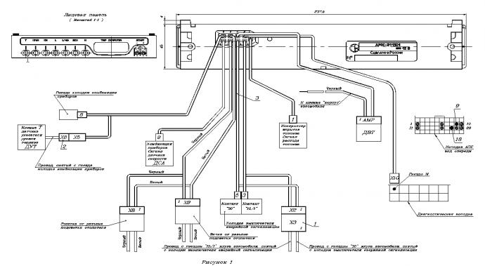
Figure 1 When the monitored parameter goes beyond the set value: maximum speed from 20 to 200 km / h, depending on the installation, mileage on the remaining fuel is less than 50 km, the voltage of the on-board network is below 10.8 V or above 14.8 V, the bell symbol »Starts blinking and a sound signal is generated: for the first two parameters with a duration of 3 s and 15 s, there is a pause, the sound signal is repeated two times. When the on-board network voltage deviates, the sound signal is generated with a 10 s delay and has a duration of 5 s and a 5 s pause, the sound signal is repeated three times. The sound signal is accompanied by the output on the indicator of the value of the controlled parameter. The sound signal is reset by pressing the "START" key. After the sound signal has been reset, the indication of the parameter exceeding the set value is accompanied by a flashing bell symbol. When the parameter returns to its normal value, the alarm stops. To set or remove the parameter control mode, it is necessary to set or clear the “bell” symbol by pressing the “START” key in the monitored parameter display mode. For example, to set the overspeed control mode, use the "KM / H" key to enter the "Instantaneous speed" mode and use the "START" key to set the "bell" symbol on the indicator. Resetting or setting the sound signal of confirmation of pressing the keys is carried out in the mode of indication of the parameter "Travel time without taking into account stops" by pressing the "START" key. Indication of the parameters: "Average travel speed", "Average fuel consumption per trip", "Mileage on the remaining fuel" is carried out when the following conditions are met: the parameter "Trip mileage" is more than 1 km and the parameter "Travel time excluding stops" is more than 1 min, up to if these conditions are met, the indicator displays the symbols "- - - -". To reset all accumulated parameters: "Travel time excluding stops", "Total travel time", "Total fuel consumption per trip", "Trip mileage", in the display mode of one of these parameters, press and hold the "START" button for more than 4 s until a two-tone beep appears. After resetting, it is necessary to check the state of the mode indicator (presence or absence of the "bell" symbol), in which the reset was performed, since it can change its state. If there is no DVT or a malfunction in its circuit in the "Temperature overboard" parameter indication mode, the "Co" symbols are displayed on the indicator.
3.2 Setting time parameters
The mode of correction of the readings of the parameters: "Current time of day", "Calendar", "Alarm" is switched on and off by pressing the "START" key. The corrected digits of the parameter are indicated by blinking. The "+" or "-" keys set the required parameter value. If the "+" or "-" keys are held down for more than 0.5 s, the autorepeat mode is activated. The clock is set according to the exact time signals as follows: in the indication mode of the “Current time of day” parameter, press and release the “START” key and, according to the sixth signal of the exact time, the “H” key is pressed, while the digits of minutes and seconds are reset to zero. If the value of the parameter "Current time of day" coincides with the set value of the alarm clock, three melodic sound signals are issued, each 30 s long with a period of 1 min. Resetting the alarm clock setting is carried out as follows: in the “Alarm” parameter display mode, press and release the “START” key and then press the “H” key. In this case, the symbols “” appear in the digital digits, and the “bell” symbol is absent in the display mode of the “Current time of day” parameter.
3.3 Clock drift correction
To reduce the error of the watch, it is possible to introduce a correction factor. To do this, in the “Current time of day” parameter display mode, press and hold the “START” key for 2 s - the “C” symbol and the flashing value of the correction factor will appear on the indicator. Use the "+" or "-" keys to enter the required value of the coefficient and, by pressing the "START" key, exit the correction mode. Are the maximum values of the correction factor equal? 31. One unit of the correction factor is equal to the change in the clock rate by 0.35 s per day for positive values and 0.18 s per day for negative values.
3.4 Setting the speed limit
The entry into the mode of setting the maximum speed is made by pressing the "START" key in the display mode of the "Average travel speed" parameter. In this case, a blinking value of the maximum speed appears on the indicator, when exceeded, an audible warning signal is generated. Changing the value of the maximum speed is carried out using the "+" or "-" keys with a step of 5 km / h from 20 to 200 km / h. The exit from the installation mode is made by pressing the "START" key.
3.5 Modes of operation of the indicator backlight
When the instrument lighting is on, the backlight level is adjusted with the backlight control on the vehicle instrument scale. With the instrument lighting off and the ignition on, the backlight level is adjusted in the following sequence: in the “Total travel time” parameter display mode, press and release the “START” button. In this case, all single segments (icons) will be displayed on the indicator, which is a sign of the backlight level adjustment mode, and in digital digits a number will be displayed corresponding to the backlight level as a percentage of the maximum value. Use the "+" or "-" keys to set the required backlight level. Each time you press the keys, the backlight level changes by 5%. If the keys are held for more than 0.5 s, the auto-repeat mode is activated. The set backlight level is retained until the next correction. To exit the adjustment mode, press the "START" key.
3.6 Setting the fuel level table
The computer memory contains tables of FLS readings with a discreteness of 3 liters (the fuel level values at intermediate points are calculated by interpolation). Depending on the type of car and the type of instrument cluster installed on the car, for the computer to display the fuel level in the tank correctly, one of the fuel level tables stored in the computer memory must be installed. Electromechanical instrument combinations can be installed on the car - they form an output signal of the fuel level with a maximum voltage of more than 5 V, or electronic instrument combinations that generate an output signal of the fuel level with a maximum voltage of up to 5 V (a distinctive feature of these instrument combinations is the presence of a liquid crystal odometer indicator) ... The procedure for setting the type of instrument cluster and the corresponding fuel level table is as follows: a) disconnect the "Battery" circuit (remove the "-" terminal battery or disconnect the harness connector from the computer); b) press one of the following keys to select the type of instrument cluster: - "L" instrument cluster of electromechanical type; - "L / 100" - electronic type instrument cluster; - "KM" instrument cluster of the car GAZ-3110; c) while holding the selected key, connect the "Battery" circuit (connect the harness connector to the computer) and after a time interval of 2 s release the key.
3.7 Calibrating the FLS
Due to the fact that a car's FLS has a large technological spread of parameters, to increase the accuracy of the fuel level readings, the computer provides a mode for correcting the FLS readings table (calibration). ATTENTION! BEFORE STARTING TARING, MAKE SURE THE FUEL LEVEL SIGNAL IS CORRECTLY CONNECTED TO THE COMPUTER AND SET THE CORRECT TYPE OF INSTRUMENT COMBINATION. The calibration procedure can be carried out at the request of the owner independently. To do this, it is necessary to drain the gasoline from the tank, leaving the minimum volume of fuel required for the operation of the gas pump (for VAZ cars it is 3 liters) - this volume is then taken as a zero level. Then enter the indication mode of the "Fuel level in the tank" parameter, press and hold the "START" key for 2 s, and a blinking number "0" will appear on the indicator. Press and hold the "L" key for 1 s until a sound signal appears to confirm the memorization of information. After that, the indicator will show a blinking number "3". Pour 3 liters of gasoline into the gas tank using a measuring container, wait the time required to set a constant fuel level, press and hold the "L" key for 1 s until a confirmation beep appears. The indicator will show a blinking number "6". Further, to continue taring, it is necessary to repeat the above procedure, each time adding 3 liters and then pressing the "L" key. In this case, it is necessary to ensure that the total amount of fuel in the tank corresponds to the value on the indicator for a particular calibration stage. To end the calibration mode after recording the last value of the fuel level, press the "START" button, turn the ignition off and on. Note - The maximum possible value of the fuel level during calibration is 72 liters.
3.8 Computer operation in diagnostic mode
3.8.1 Reading fault codes Entering the mode by first pressing the "ECU" key. The computer display will show the symbols "En.NN", where NN is the total number of fault codes accumulated in the ECU memory. The "+" and "-" keys select the malfunction number. For an ECU installed on a car of the VAZ family, the malfunction number is displayed on the indicator as a combination of symbols "EX.NN", where EX is the malfunction status, NN is the malfunction number. An example is E0. 1. Values of the status of the code of malfunctions for ECU MP7.0 are shown in Table D.3.2. For an ECU installed on a car of the GAZ family, the malfunction number is displayed on the indicator as a combination of symbols "ENNN", where NNN is the malfunction number. If the total number of faults is 0, then the fault numbers are not displayed. Switching the indication to view the malfunction code and back (to view the malfunction number) is carried out by short (less than 1 s) pressing the "START" key. Using the "+" and "-" keys, you can view all fault codes. Possible values of fault codes are given in Appendix D. 3.8.2 Resetting fault codes All fault codes stored in the ECU memory are reset by pressing and holding for 2 s the "START" button in the mode of indication of codes or numbers of faults. 3.8.3 Selecting the ECU type The computer can be installed on vehicles with engines equipped with different types ECU. To select the type of ECU, enter the ECU parameters display mode (in the absence of communication with the ECU, the computer display will display the symbols "Ps.-" and the blinking "bell" symbol), press and hold the "START" key for 2 seconds until the indicator of the symbol "ECU" (ECU) and a flashing digit, which determines the type of ECU. Use the "+" or "-" keys to select the required type of ECU and exit the mode by pressing the "START" key. To establish communication with a new type of ECU - turn off and then turn on the ignition. When choosing the type of ECU, the indicator displays: - "ECU.0" - M1.5.4; - "ECU.1" - M1.5.4N or January-5.1; - "ECU.2" - MP7.0; - "ECU.3" - MIKAS 5.4, MIKAS 7.1, 301.3763 000-01. 3.8.4 Reading ECU parameters The mode is entered by pressing the "ECU" key. The indicator displays the symbols “Ps. 1 ", where Рс is the indication of the ECU parameter number, and 1 is the parameter number. Use the "+" and "-" keys to select the parameter number. Switching the display to view the parameter value and back (to view the parameter number) is carried out by short (less than 1 s) pressing the "START" key. The keys "+" and "-" are used to view all parameters. The list of the ECU parameters displayed on the computer indicator is given in Appendix D. 3.8.5 Reading the ECU identification data (the function is not available if the ECU type MIKAS 5.4, MIKAS 7.1, 301.3763 000-01 is selected) The mode is entered by pressing the "ECU" key. The display shows the symbols “Cu. 3 ", where Cu is the indication of the identification data number, and 3 is the data number. Switching the indication to view the data value and back (to view the data number) is carried out by short (less than 1 s) pressing the "START" key. The keys "+" and "-" are used to view all data. The list of ECU identification data displayed on the computer indicator is given in Appendix D.
3.9 "Parking" function
3.9.1 The "Parking" function is performed only when a car parking device is connected to the computer. After switching on the transmission on the vehicle reverse and the ignition is switched on on the indicator for 1 s the inscription "rdy" (abbreviation from the English ready - "ready") appears and three short beeps sound. This means that the car parking device is intact and ready to work. If the obstacle is not detected, then the symbols "----" are displayed in digital digits on the indicator. If the distance to the obstacle is in the range from 40 to 170 cm, then the indicator shows the distance in centimeters. The direction to the obstacle is shown by the indicator symbols located below the digital digits: “< » - препятствие расположено слева от автомобиля; « >»- the obstacle is located to the right of the vehicle. If the obstacle is located in the center of the vehicle, both symbols are displayed.
3.9.2 The indication of the distance to the obstacle is accompanied by sound signals (when the “bell” symbol is set on the indicator), which become more frequent as the obstacle approaches. When the distance to the obstacle is from 170 to 90 cm, the frequency of occurrence of sound signals is 3 signals / s, from 90 to 60 cm - 5 signals / s, from 60 to 40 cm - 8 signals / s. When the distance to the obstacle is less than 40 cm, the sound signal becomes continuous and the display shows the inscription "StOP". Sound signaling when indicating the distance to an obstacle can be enabled (the indicator has a bell symbol blinking at a frequency of 1 Hz) or disabled (there is no bell symbol). The “bell” symbol is reset and installed by long pressing (more than 2 s) of the “START” button. When the "bell" symbol is set, the sound signal can be turned off until the end of the car's reverse mode by short (no more than 1 s and no less than 0.3 s) by pressing the "START" button - the "bell stops flashing" symbol.
3.10 Auxiliary computer operation modes 3.10.1 Correction of fuel consumption readings
The computer readings of the fuel consumption parameters may differ from the actual values for various reasons: carburetor engine, deviation of pressure in the fuel rail or clogged injectors in vehicles with an engine equipped with an ECM. To correct the fuel consumption readings, enter the “Current fuel consumption” display mode, press and hold the “START” button for 2 s until the flashing value of the correction factor appears on the indicator. The nominal value of the correction factor is 100 (in percent). The change in the value of the coefficient is made with the "+" or "-" buttons, while the larger value of the coefficient corresponds to an increase in the fuel consumption readings, and to the lower one - a decrease in the fuel consumption readings. To exit the correction mode, press the "START" key. The correction factor can be determined as follows. Generate fuel up to a certain value of the fuel level reading by the computer. Pour a measured amount of fuel into the tank - for example, 20 liters. Reset the total fuel consumption readings in the computer, for which, in the "Total fuel consumption" display mode, press and hold the "START" button for 4 seconds until a two-tone sound signal appears. Develop all the fuel filled up to the initial value of the fuel level reading. Note the total fuel consumption reading - e.g. 25 liters. Calculate the value of the correction factor: (20/25)? 100 = 80 Enter the calculated value of the correction factor into the computer. The range of values of the correction factor is from 50 to 255. After that, reset the fuel consumption readings.
3.10.2 Correction of the voltage readings of the on-board network
The voltage readings of the on-board network are adjusted during the manufacture of the computer and after the repair of the computer associated with the replacement of the lithium battery. To carry out the correction, it is necessary to press and hold the START button in the "On-board network voltage" display mode for 2 s until the blinking voltage value appears. Use the "+" or "-" keys to set the voltage value equal to that measured by a digital voltmeter on contact "3" of the computer block. Exit the correction mode by pressing the "START" key.
3.10.3 Checking the software version number
To control the version number of the computer software, press the "-" key and hold it to turn on the ignition. The display will show the symbols "ПР55" - where the first digit 5 defines the type of computer (AMK-211501), and the second digit 5 - the number of the current software version (may differ upwards).
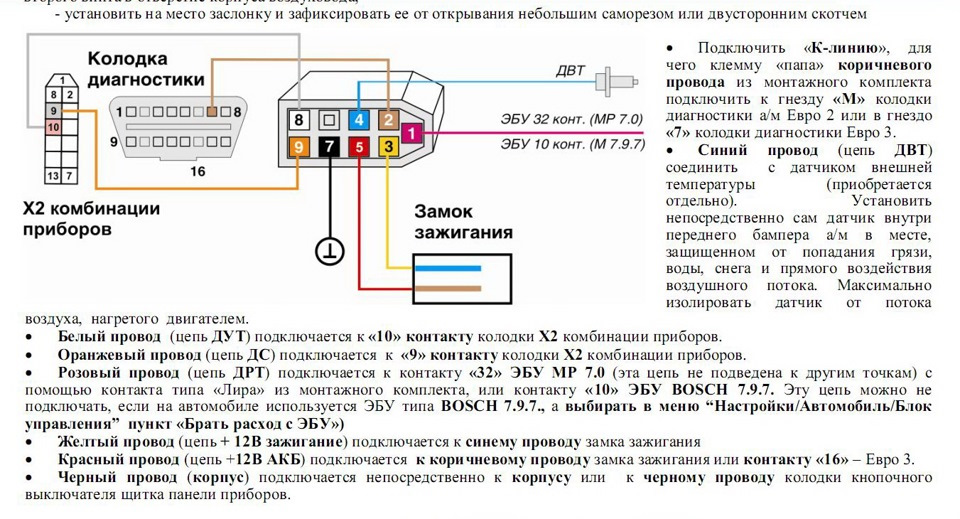
4 Installing the computer on the car
The names of signals and numbers of contacts of the computer plug are shown in Table 1. Table 1
|
Signal name |
Signal designation |
Plug contact number |
| DRT output signal | ||
| Diagnostic bus "K-line" | ||
| Powering the computer through the ignition switch | ||
| DVT output signal | ||
| Powering the computer from a rechargeable battery | ||
| Switching on the backlight mode | ||
| Frame | ||
| FLS output signal | ||
| DSA output signal |
Description of computer pins is given in Table 2 Table 2
| Fuel consumption signal input... Pulse signal of rectangular shape with a frequency proportional to fuel consumption. Signal source - contact "2" DRT or contact "54" ECU (fuel injection controller) type M1.5.4 (January-5.1) or contact "32" ECU type MP7.0. | |
| Line "K" diagnostics... The contact is connected to the contact " M"Pads for diagnostics of VAZ cars or contact" 11 »Pads for diagnostics of GAZ vehicles. On this line, the computer exchanges information with the ECU. The data is transmitted as a series of pulses with an amplitude of low level(0 V) to the voltage of the on-board network. The line goes through the contacts " 9 " and " 18 »Of the control unit of the car anti-theft system (hereinafter - APS), which must be closed when it is absent or when the APS is not activated. The signal" K-line "from the car parking device is connected to this contact. | |
| Voltage signal input from ignition switch... The signal from the ignition switch does not power the computer, it informs the computer that the ignition is on. Used to measure the voltage of the on-board network. | |
Continuation of table 2
| DVT signal input... The computer sends along this circuit through an internal resistor a voltage of +5 V to the DVT, which is a thermistor, the second terminal is connected to ground. The sensor changes resistance depending on the temperature. | |
| Non-disconnectable voltage input... Constant power supply of the computer from the vehicle's on-board network. The voltage is supplied through a fuse. | |
| Voltage input of the car instrument scale illumination circuit... The signal controls the brightness of the computer indicator backlight. | |
| Frame... The contact is connected to the vehicle body (ground). Contact voltage should be close to zero. | |
| Fuel level input... The contact is connected in parallel to the signal circuit of the car's FLS. The place of connection is the connector of the instrument cluster of the car. The signal voltage value is used to calculate the fuel level depending on the type of instrument cluster and the installed fuel level table. | |
| DSA signal input... A square-wave pulse signal with a frequency proportional to the vehicle speed. The signal comes from the contact "2" of the DSA of the car or from the output of the instrument cluster (speed signal for the computer) or from the contact "9" of the ECU type М1.5.4, January-5.1, МР7.0. |
4.1 Installing the computer on a car with a carburetor type engine
The computer is installed in the car interior in a special socket of the instrument panel (Figure 2) or in any place convenient for observation, taking into account the optimal viewing angle of the indicator corresponding to the position of the clock hand at 10 hours 30 minutes (to the left and above from the perpendicular to the indicator plane), using bracket included in the KMCH. Connect the computer and sensors to the car according to Figure 2 using the KMCH (the positions indicate the elements of the KMCH): 1 - Screw V.M6-6g x14.58.016 GOST 1491-80 - 2 pcs. 2 - Nut М6.58.016 GOST 5927-70 - 2 pcs.
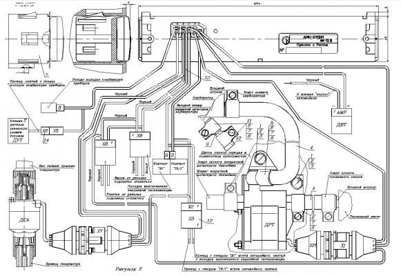
Figure 2 3 - Washer 6.01.10.016 GOST 11371-78 - 4 pcs. 4 - Hose (outer diameter 14.5 mm) - 2 pcs. 5 - Clamp (inner diameter 14.5 mm) - 2 pcs. 6 - Nut (square) - 4 pcs. 7 - Screw V.M4-6g х12.58.016 GOST 1491-80 - 4 pcs. 8 - Washer 4.01.10.016 GOST 11371-78 - 8 pcs. 9 - Hose (outer diameter 10 mm) - 1 pc. 10 - Plug - 1 pc. 11 - Clamp (inner diameter 10.5 mm) - 2 pcs. 12 - Block X3 - 1 pc. 13 - Harness - 1 pc. 14 - Block X6 - 1 pc. 15 - Bracket - 1 pc. 4.1.1 Installing the DSA To install the DSA, it is necessary to perform the following operations: - disconnect the flexible shaft of the speedometer cable from the gearbox speedometer drive; - connect to the speedometer drive of the DSA gearbox with a tightening torque of 6 to 8 Nm; - connect the flexible shaft of the speedometer cable to the output shaft of the DSA, having previously twisted the protective cap from the DSA. 4.1.2 Installing the DRT To install the DRT, it is necessary to perform the following operations: - fix the DRT with the fasteners pos. 1, 2, 3 on the car body in the engine compartment so that the “Exit” branch pipe of the DRT is located horizontally and below the fuel supply pipe of the carburetor at a distance of 10 to 20 mm; - remove the hose connecting fuel pump and a carburetor; - install the hoses pos. 4, connecting the fuel pump with the “Inlet” branch pipe of the DRT and the “Outlet” branch pipe of the DRT with the inlet union of the carburetor using fasteners pos. 5, 6, 7, 8; - remove the hose from the outlet fitting of the carburetor return line and install it on the “Return” branch pipe of the DRT; - put the hose pos. 9 with plug pos. 10, fixing it with fasteners pos. 6, 7, 8, 11, to the outlet fitting of the carburetor return line. Note - When installing DRT on cars, in fuel system which there is no return line, the plug pos. 10 install DRT on the “Return” branch pipe. 4.1.3 Installing DVT DVT should be installed inside the front bumper in a hole with a diameter of 12 mm on its lower plane on the left in the direction of the vehicle. 4.1.4 Connecting the computer to the car circuits
Connect the computer and sensors to each other and to the electrical equipment of a car such as VAZ 2108, VAZ 2109 in the following sequence: - open the hood of the car. Disconnect the wire from the "-" terminal of the storage battery; - remove the handles from the levers of the ventilation and heating system control panel. Unscrew the four self-tapping screws securing the instrument panel console overlay and take it away from the instrument panel; - remove the socket contacts of the red-black and orange wires from the block of the alarm switch (circuits "15/1" and "30") and connect them using the block pos. 12 ("X3") to the plug "X2" of the harness pos. 13. In place of the socket contacts removed from the block of the alarm switch, connect the socket contacts "5" (circuit "30"), "3" (circuit "15/1") of the harness pos. 13; - disconnect the two-terminal block of the car's wiring harness, white and black, suitable for the backlight lamp of the levers of the ventilation and heating system control panel, and connect the corresponding two-terminal blocks "X8", "X9" of the harness pos. 13 with white and black wires; - disconnect from the instrument cluster block the wire with the socket contact coming from the FLS in accordance with the car's electrical circuit and connect it using the block pos. 14 ("X6") to the block "X5" of the harness pos. 13. In the socket of the block of the instrument cluster, instead of the removed wire, install the socket contact "8" of the harness pos. 13; - unscrew the two nuts securing the mounting block and lift it up until a gap is formed between its body and the rubber gasket, into which wires with two three-terminal blocks "X1" DRT and "X7" DSA should be drawn from the passenger compartment into the air supply box. Replace and secure mounting block; - squeeze the rubber seal out of the hole in the center of the bulkhead of the air intake box and the engine compartment. Pass the sensor wires through the hole. Cut the rubber seal from edge to center, insert the sensor wire into the cut and install the seal in place; - connect the pads of the wiring harness pos. 13 to sensors: block "X1" to DRT, and "X7" to DSA. Connect DVT to the AMR block of the harness pos. 13. Connect the nine-terminal block "XS" of the harness pos. 13. Insert the computer into the socket of the instrument panel. Depending on the type of instrument cluster, install the fuel level table in accordance with 3.6.
4.2 Installing a computer on a VAZ car with an engine equipped with an ECM
Connect the computer to a VAZ car with an engine equipped with an ECM, according to Figure 1 using KMCH1 (the positions indicate the KMCH1 elements): 1 - Block X3 - 1 pc. 2 - Block X6 - 1 pc. 3 - Harness - 1 pc. 4 - Bracket - 1 pc. Socket contact "1" of the harness pos. 3 (fuel consumption signal circuit) connect to the vehicle's ECM harness block in accordance with the vehicle's electrical wiring diagram. Socket contact "9" of the harness pos. 3 (a circuit with a signal from the DSA), connect to the instrument cluster (if there is an output for connecting a computer) or to the car's harness block connected to the ECM. Plug "X10" harness pos. 3 is connected to the contact "M" of the vehicle diagnostic pads. Note - If the APS is not installed in the car, then in the block of the APS control unit it is necessary to install a jumper between the contacts "9" and "18". Connect DVT, FLS, as well as power and backlight circuits in the same way as in 4.1.4 or in accordance with the car's electrical circuit and the purpose of the signals given in Table 1. Connect the nine-terminal block "XS" of the harness, pos. 3, to the computer. Insert the computer into the socket of the instrument panel. Depending on the type of instrument cluster, install the fuel level table in accordance with 3.6. On a VAZ-2115 car, produced after January 1, 2002, with an engine equipped with an ECM, the computer is installed in its regular place without using the KMCH1. The connection to the car's circuits is made to the car's harness block located in the niche for installing the computer. Note - DVT installed in VAZ 2115 cars can only be used in conjunction with one of the devices: a combination of devices or a computer, while the DVT circuit from a device in which this DVT is not used must be disconnected.
4.3 Installing a computer on a GAZ-3110 car
Install the computer on a GAZ-3110 car with MIKAS 5.4, MIKAS 7.1, 301.3763 000-01 ECUs using KMCH2, which includes RYUIB6.640.786 harness and RYUIB6.133.502-01 Bracket. The computer is installed using a bracket in the passenger compartment in a place convenient for observation, taking into account the optimal viewing angle of the indicator, corresponding to the position of the arrow at 10 h 30 min (to the left and above from the perpendicular to the plane of the indicator).
4.3.1 Installation work on connecting the computer to the circuits of the GAZ-3110, GAZ-3102 vehicles using the KMCH2 should be carried out in accordance with Figure 3 as follows. Unscrew the four fastening screws and remove the instrument cluster trim by pulling it out towards you. Mark and disconnect connectors for center light switch and headlight range control. Remove the four screws securing the instrument cluster. Turn the instrument cluster 90? and remove from the dashboard. Disconnect the vehicle harness connectors from the instrument cluster. Remove the socket contact "7" from the block of the harness of the vehicle "XP2", insert it into the block "X7", which is included in the KMCH2 and connect it to the block "X6" of the harness of the KMCH2. Insert the socket contact "6" into the socket "7" of the socket "XP2". Remove the socket contact "5" from the block of the vehicle harness "XP1", insert it into the block "X8" and connect it to the block "X5" of the harness KMCH2. Insert the socket contact "8" into socket "5" of the block "XP1". Remove the socket contact "2" from the block of the vehicle harness "XP3", insert it into the block "X3" and connect it to the block "X10" of the harness KMCH2. Insert the socket contact "3" into socket "2" of the socket "XP3". Remove the socket contact "10" from the block of the vehicle harness "XP3", insert it into the block "X11" and connect it to the block "X9" of the harness KMCH2. Insert the socket contact "9" into the socket "10" of the block "XP3". Pull the wire from the contact "2" of the block "XS" of the KMCH2 harness through the rubber seal into the engine compartment of the car to the diagnostic block located on the front panel to the right of the driver. Strip the insulation off a 5 mm long section of the wire (gray with red stripes) connected to the contact "11" of the diagnostic block at a distance of 3 cm from the contact. Using the wrapping method, connect the wire to the stripped area and insulate it with PVC tape. Install DVT into a 12 mm hole on front bumper car on the left in the direction of travel. Pull the "X4" connector with the wires through the rubber seal into the engine compartment and then connect to the connector

click to enlarge
Figure 3 DVT. Connect the short wire from the "X4" connector to the car body under one of the screws. Remove the two lower screws securing the front ashtray panel. Open the ashtray and remove the two upper screws securing the front ashtray panel. Pull out the front ashtray panel towards you. Disconnect the cigarette lighter plugs. Connect the X2 pin block of the KMCH2 wiring harness to the cigarette lighter socket included in the car wiring harness. Connect the cigarette lighter plug to the "X1" socket of the KMCH2 wiring harness. Connect the “XS” block of the KMCH2 harness with the computer block. Install the cigarette lighter panel and instrument cluster in place. 4.3.2 Set the type of instrument cluster for GAZ-3110 vehicles in accordance with 3.6. 4.3.3 Select the type of ECU-3 controller (ECU.3) in accordance with 3.8.3.
4.4 Installing the car parking device
The car parking device consists of a control unit to which the impulse sensor R (right), the impulse sensor L (left) and the X1 harness are connected, as well as a bracket for attaching the sensors to the car (at the discretion of the consumer). Install the control unit in the passenger compartment or in the luggage compartment; install the sensors on the rear bumper of the vehicle. Detailed recommendations on options for installing sensors are available in the accompanying documentation for the car parking device РЮИБ.453688.501 ET. Connect the car parking device to the car circuits in accordance with Figure 4. Lay the wires of the power harness of the car parking device from the control unit to the place where the computer is installed. Remove the socket contact of socket "7" from the block "C" of the harness for connecting the computer to the car circuits, remove the housing "X6" from the socket contact of the black wire of the power harness of the car parking device and put it on the socket contact removed from the socket "C", connect the socket contact in the housing "X6" with plug "X5". Insert the female contact of the black wire of the power harness of the car parking device into the socket "7" of the block "C". Connect the short red wire to the power circuit of the reversing lights, leave the red wire with a female contact in the “X8” housing unconnected. Remove the socket contact of socket "2" from the block "C" (if it is there), remove the housing "X7" from the socket contact of the green wire of the power harness of the car parking device and put it on the socket contact removed from the block "C", connect the socket contact in the housing "X7" with plug "X9". Insert the socket contact of the green wire of the power supply harness of the car parking device into the socket "2" of the block "C". After completing the installation operations, connect the plug-in connectors to the control unit in accordance with Figure 4.
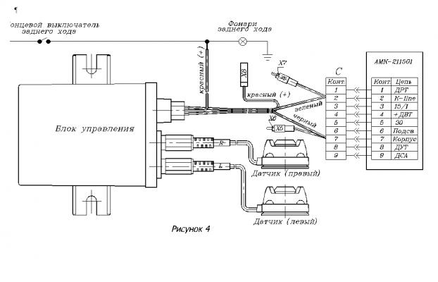
Figure 4
5 List of possible malfunctions and methods of their elimination
Scroll possible malfunctions and methods of their elimination are shown in Table 3. Table 3
|
Malfunction name, external manifestation and additional symptoms |
Probable cause of malfunction |
Troubleshooting method |
| No indication of the "Current time of day" parameter when the voltage of the "Battery" circuit is connected ("thirty") | "5" computer pads | |
| After turning on the ignition switch, only the indication mode of the "Current time of day" parameter works | Malfunction in the contact circuit "3" computer pads | Check wires and their connections, replace damaged wires or contacts |
| Computer readings glitches | Unreliable contact in the computer wiring circuits | Check and restore reliable contact in the wire connection circuit |
| Flashing numbers on the indicator | The mode of correction of one of the parameters is on | Press the " START» |
| There is no indication of the "Current fuel consumption" parameter, and the readings of the "Total fuel consumption per trip" parameter do not increase | Malfunction in the contact circuit "1" computer pads, no signals from DRT or fuel injection controller | Check wires and their connections, replace damaged wires or contacts and, if necessary, sensors |
| There is no indication of the "Instantaneous speed" parameter, the indication of the "Current fuel consumption" parameter is only in l / h at a speed of more than 20 km / h | Malfunction in the contact circuit "nine" computer pads, no signal from DSA | Check wires and their connections, replace damaged wires, contacts or DSA |
| The voltage readings of the on-board network differ significantly (downward) from the voltage on the battery | Large voltage drop at the contacts of the ignition switch | Clean the ignition switch contacts |
6 Transport and storage
Transportation of the computer is carried out by any type of transport that ensures its safety from mechanical damage and atmospheric precipitation, in accordance with the rules for the carriage of goods in force for this type of transport. The transportation conditions for the computer correspond to group C GOST 23216 78 in terms of mechanical influences and group 2 C GOST 15150 69 in terms of the impact of climatic factors. The computer should be stored in the manufacturer's packaging under the conditions of 2 C in accordance with GOST 15150 69. The period of transportation of the computer from the manufacturer to the consumer should not exceed 9 months from the date of manufacture of the product. The count is based on the product labeling.
7 Manufacturer's warranty
The manufacturer guarantees the compliance of the computer with the requirements of TU 4573 043 00225331 01 provided that the consumer observes the conditions of transportation, storage and operation established by this passport. The warranty period for the computer is 12 months from the date of sale. The warranty period for storing a computer in the manufacturer's packaging, subject to the requirements established by this passport, must be at least three years from the date of manufacture.
8 Disposal
All assemblies and case parts of the computer are made of materials that have passed the environmental examination, and their disposal does not harm the environment.
9 Certificate of packing
Route computer AMK-211501 serial number ________________ is packed at Kursk JSC "Schetmash" in accordance with the requirements stipulated in the current technical documentation. ______________ ___________________ personal signature transcript of signature _______________ year, month, day
10 Certificate of acceptance and sale
The route computer AMK-211501, serial number ________________ was manufactured and adopted in accordance with the current technical documentation, complies with TU 4573 043 00225331 01 and is recognized as suitable for operation. OTK stamp ______________ ___________________ personal signature signature decryption _______________ year, month, date Sold ___________________________________________________________ name of the trade enterprise Date of sale "____" _______________________200___ Store stamp Signature of the seller
Appendix A (informative) Parameters of sensor output signals
А.1 The computer provides reception of a signal from the DSA with the following parameters: - conversion factor (number of pulses per one meter of distance traveled) ………………………………………………………………………………………………………………………………… ….…. ………. …… .... 6; - input voltage of low level, V, no more ………. …….… 0.8; - high-level input voltage, V, not less. …… .. …….… 4.0; - fill factor Q = (50 ± 30)%; - the duration of the leading (trailing) edge of the pulse, μs, no more ... 50. Electrical diagram connecting DSA to a computer - an open collector of an n-p-n transistor. A.2 The computer provides reception of a signal from the DRT or the fuel injection controller with the following parameters: - conversion factor (number of pulses per liter of flowing fuel) …………. ……………… ........... ............. ……… .. 16,000; - input voltage of low level, V, not more ……………… ..... 1.0; - high-level input voltage, V, not less ……………… .... 9.6 (or 0.8 UА, where UА is the voltage on the + 12 V bus of the fuel injection controller); - fill factor from 30 to 70%. The electrical connection diagram is an open collector of an n-p-n transistor with a load resistor on the + 12V bus of the fuel injection controller. А.3 Parameters of DVT are given in Table А.1. Table A.1
Continuation of table A.1
A.4 The signal parameters of the FLS of the electromechanical instrument cluster for VAZ vehicles at a supply voltage of 13.5 V are given in Table A.2. Table A.2
A.5 The dependence of the FLS resistance on the fuel level in the tank of a vehicle with an electronic instrument cluster is shown in Table A.3. Table A.3
|
Fuel volume in the tank, l |
FLS resistance, Ohm |
A.6 The parameters of the FLS signal of the instrument cluster for GAZ-3110 vehicles at a supply voltage of 13.5 V are shown in Table A.4. Table A.4
|
Fuel volume in the tank, l |
FLS voltage, V |
Appendix B (reference) Parameters and sequence of switching computer display modes