Nowadays, many car owners are striving to install an on-board computer in their cars. And this desire is quite justified, since this useful and convenient multidimensional device provides many demanded functions. For example, the on-board computer VAZ 2109 allows not only to increase the comfort of being in the car, but also to choose the most optimal driving mode in any conditions.
In order to install a VAZ carburetor on-board computer, you will need the previously purchased device itself, the corresponding adapter and cable-wire. When integrating functional unit in Kalina and Priora, which clearly do not represent a Zhiguli concept car, you first need to remove the radio tape recorder from the installation place and remove the cover with the OPEN inscription. Then, in the back wall of the lid compartment, a round 17 mm hole for the cable or its rectangular analogue with a dimension of 17 × 10 mm is drilled. Special care should be taken during this process to avoid damaging extraneous wires.
Then the cable is passed through the resulting hole, the compartment for small items is removed, instead of which a connection adapter is installed, a loop is threaded and the adapter is fixed with the screws remaining from the compartment for small items. After that, the signal loop connector is connected to the tap located on the diagnostic block, the previously removed parts are integrated and secured with a standard mount. As a result, it remains only to install the on-board computer itself, the VAZ carburetor.
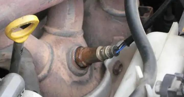
In the front-wheel drive Lada Samara 1 and 2 families, the device is installed instead of the plug located on the console. Removing it, you can find a 9-pin standard connector for its connection. The brown wire is commutated with the M socket of the diagnostic block in Euro2 cars and with analogue 7 - in Euro3 cars. The other end of this wiring is plugged into socket 2 of the functional unit connector, which is located at the bottom of the dashboard. The blue wire connects to socket 4 of the device, and the internal temperature sensor is led out under the hood.

To install an on-board computer or model 2108 for a VAZ 2109, the following connections are additionally made. The white cable of the fuel level sensor circuit is connected to pin 11 of the instrument cluster or to the pink wire with a red stripe. Orange cable - to output 2 of the ECU block located under the passenger compartment trim next to the driver's left foot. Pink analogue - to the 3rd output of the same block.

In VAZ 2110-12 models, an on-board computer can be installed, and later, instead of a clock on the dashboard, for which they are removed, and the above process is implemented. The temperature sensor is installed in front bumper with the expectation of its protection from water, snow, dirt and air flow. In VAZ cars manufactured earlier than 2001, there is often no connection with the fuel sensor. In this situation, pin 8 of the device connector is connected to the pink cable 20 of the output of the red instrument cluster panel.

On-board computers are used to identify visible and hidden vehicle malfunctions. They allow the car enthusiast to carry out repair operations in a timely manner. Thanks to on-board computers, you can significantly save money on diagnostics in car services.
Preparing for installation
So, you have decided to equip your car with such a device. Let's consider how to install an on-board computer. If the specialists do not want to pay money, then you need to install it yourself. Let's move on to exploring the installation process.
- First, we need to remove the negative terminal from the battery by opening the trunk. We go into the salon and remove the stove adjustment knobs.
- Next, we need to unscrew two screws. In the glove box, we see two black screws, it is them that need to be unscrewed, and then we take out this box.
- Now we need to remove the front panel by pulling it towards ourselves.
- Remove the panel very carefully, as there is a possibility of breaking it. Disconnect the wires carefully in advance.
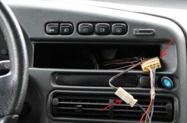
- The green wire of the fuel quantity sensor is connected to the wires that are intended for connection to the on-board computer.
- Look, maybe you have a separate connector for the BC. If so, then there should be no connection problems. But if this is not the case, or you cut it off, then you have to tinker with the wires.
- V domestic cars there is a white data bus wire, we will connect it to the connector in the car. How to do this is written in the instructions. Now we can connect the on-board computer.
Find out if it is possible to install an on-board computer on your car, preferably in a store.
Installing the on-board computer
We put the mass of the battery back, turn on the ignition and wait until the on-board computer determines which electronic control unit to work on.
After all this, we do everything according to the instructions:
- We set the correct date and time;
- We indicate how much gas tank we have;
- We indicate the boundaries of warnings (this may be a warning "Engine is warmed up", etc.);
- We need to make sure that the on-board computer correctly detects the speed of movement, because if it is incorrectly displayed, the fuel consumption will be shocking;
- Now we adjust the tank calibration. At the time when the yellow lamp lights up - there are 15 liters in the tank, we indicate this in the settings. Refuel at full tank and this is also indicated in the settings.
Everything. With basic installation steps on-board computer we got acquainted with the car. It remains only to check, test the device, whether everything works. Also look at the computer settings yourself, because on-board computers have a lot of possibilities. We hope that this manual will help everyone who has bought and wants to install an on-board computer on their car on their own.
› Installation of the on-board computer MultitronicsIn principle, everything is quite simple, and if you are in no hurry, the process takes only a couple of hours.
Go!
When installing this Trip Computer (MC), we will have to disconnect the chips from the engine control unit, as well as from the dashboard, so first you need to disconnect the ground from the battery. Do not forget that after this head unit When turned on, it will ask for an unlock code!
First of all, you need to decide on the place of installation of the MK. I decided that it would be optimal for me to install it under a small glove compartment near the rearview mirror. The view to it does not obscure anything, when parking it is convenient that the numbers before the obstacle are near the mirror, which you constantly look at, and in my Toyota Celica I have similar devices under the ceiling, and I am already quite used to them.
Since I did not want to glue the MK stand on the double-sided tape (it is not very reliable, and the tape leaves marks when peeled off), I had to cut four longitudinal holes in the stand, which is intended for mounting on the windshield, using a thin drill with a dremel.
And then with a pair of black cable ties, this stand is attached to the glove compartment mesh. Strong and neat!

I connect the data cable to the connectors on the back of the MK, as well as the signal wires of the parking sensors. Damn, I have never met that the connector is inserted not from the first marked contact, but from the second! That is, the three-pin connector must be connected to the second-third-fourth pins according to the instructions! Engineers are harnessing!
We screw the device to the gray body, and the body to the fixed holder. Gray plastic fits well into the interior of the Element.
I neatly folded the flat cables into a tube and tucked them into a thin corrugation so that the wiring would not be conspicuous.

Remove the rack trim. It rests on two caps, to remove it we put a flat screwdriver on top, and then pull it with our fingers towards passenger seat... At the bottom, turn off the chip leading to the squeaker and remove the plastic.
We stretch the loops under the casing, after which you can put the casing in place.
We finished with parking sensors, everything should work. We stretch the main cable, securing it along the way with clamps, to the OBD2 connector, and insert it into the connector. In principle, the installation could be completed at this point, the computer will not calculate only the remaining fuel in the tank, but we will go further.

We open the glove compartment. Using a flat screwdriver, we pry on the travel stops at the edges, and when they snap off, we pull them out.
The brains are already close. We remove the large flat chip from the clip so that it does not get in the way (I just pressed the chip from top to bottom, and it jumped off) and move it to the side.
From the brains we take out the following chips from the top in the account: the first (chip E) and the fourth (chip B).
Next is the most difficult moment. On chip B, wires 2 (yellow), 3 (blue), 4 (red) and 5 (brown) are responsible for the action from 1 to 4 injectors, you can connect to any wire, I chose brown, since it was on the edge. The wiring of the chip is short, and it itself is located in the depths of the glove compartment, so in order to remove two millimeters of insulation from the wire with a knife, I had to sweat a little. We wind here the blue wire from the MK block, which is responsible for connecting to the injector, after which we isolate the junction.
With chip E, everything is much easier, since here the wiring is an order of magnitude longer. In the bottom row, the third wire (blue) is responsible for the tachometer signal (in some MK models it is involved, but not in mine), and the fourth wire (blue with a white stripe) is responsible for the signal from the speed sensor, we connect the purple wire from the MK pad to it ... In principle, the computer can take data on the operation of the injectors and the current speed from the OBD2 connector, but connecting directly to the brain gives much more accurate measurements, as stated in the instructions. We put the chips back into the brains, attach the flat chip in place, fasten our two wires with clamps so that they do not dangle - and that's it, the glove compartment limiters can be put in place!
Of all the wires present on the trip computer block, only the following were needed:
Blue (nozzle)
Purple (speed sensor)
Green (gas tank sensor, about it later)
DO NOT NEED, since the voltage and data are taken from the OBD2 connector:
Red with yellow (plus from the battery and plus from the ignition switch)
Black (mass)
White (K-Line, OBD2 data)
Brown (the size seems to automatically dim the brightness of the computer display, but I don't need this chip).
To prevent the wires from interfering, I cut off most of them, after which it is imperative to insulate SEPARATELY the end of each wire, otherwise a short circuit of the OBD2 connector with all the consequences is possible!
It's the turn of the tidy. Use a flat screwdriver to pry the black plastic from the side of the door, pull it towards you (across the body of the car, as if opening the driver's door) - it keeps on latches. We unscrew one screw securing the trim from the end, after that, sitting in the driver's seat, we pull the plastic trim around the dashboard towards ourselves, starting with the air duct - everything there also keeps on latches.
We unscrew the four screws that hold dashboard, and take it out.
On the first (large) dashboard chip, contact number 17 (bottom row, third from the bottom, yellow wire with a black stripe) is responsible for reading the fuel level in the tank. We stretch the green wire from the MK block under the torpedo to the dashboard harness and connect to the yellow-black wire.
We put in place the dashboard and plastic trim.
I wound the three wires that I connected in one bundle and placed them next to the standard wiring chips behind the subwoofer so as not to interfere. Now it's the turn of the outside temperature sensor.
I pack the temperature sensor wire together with my two signal wires in a thin corrugation.
We stretch the corrugation to the headlight, fasten it with clamps along the way.
The temperature sensor wire was just centimeters long enough to attach it under the Honda emblem as shown. From the street it is absolutely invisible, when driving, it shows the exact temperature, when you stand in traffic for a long time - it starts to heat up and lie a little, but this is not critical. In principle, you can find another place for him if you want.
Next, we screw the battery terminal into place and start the engine. MK will be busy for several minutes with autodetection of the protocol, after that, according to the instructions, we perform the following points:
1. Setting the date and time
2. In the settings, we indicate the data sources for the injectors, speed and tank not "ECU", but our connected wires (otherwise the meaning of the connection is lost).
3. We indicate the volume of the tank - 60 liters
4. We indicate the limits of warnings (for example, I set the warning "The engine is warmed up" at a coolant temperature of 55 degrees (when the temperature arrow began to move and crossed the left border of the scale) - the computer will inform you that you can start moving.
5. Make sure that it correctly shows the speed of the car (by default on the first screen of the user) - if the speed is wrong, the flow rate can be fantastic. I needed to set the speed ratio to 140% so that the speedometer and MK began to show the same numbers, and the flow was adequate.
6. We calibrate the tank according to the instructions (when the yellow light comes on - there are 15 liters in the tank, go to the settings and indicate it), then refuel until the pistol is cut off, in the 60 liters tank, again, according to the instructions, go to the settings and indicate this.
The main thing seems to be everything. In general, you have to climb the settings yourself - this computer has a lot of possibilities!
Hope this report helps those looking to install trip computer on one's own! There is nothing complicated about that!
Price tag: 3 000 ₽