|
|
Rice. 7.6. Connection diagram of the mounting block (the outer number in the designation of the wire end is the number of the block, and the inner number is the conditional number of the plug): K1 - washer time relay rear window; K2 - relay-interrupter for direction indicators and alarm; K3 - wiper relay; K4 - relay for monitoring the health of lamps (contact jumpers are shown inside, which are installed instead of the relay); K5 - turn-on relay high beam headlights; K6 - headlamp cleaning relay; K7 - power window relay; K8 - relay for turning on the sound signal; K9 - relay for turning on the electric motor of the fan of the engine cooling system; K10 - relay for turning on the rear window heating; K11 - relay for switching on dipped headlights |
Most of the fuses and auxiliary relays are located in a separate mounting block (Fig. 7.3) installed in the air intake box on the left side of the vehicle. Through the mounting block, the wires of the engine compartment are connected to the wires of the instrument panel and the interior of the car. The location of the blocks and the conditional numbers of the plugs in the connecting blocks of the mounting block are shown in Fig. 7.4 and 7.5. A diagram of the internal connections of the mounting block is shown in Fig. 7.6.
|
|
Rice. 7.6b. Connection diagram of the mounting block (the outer number in the designation of the wire tip is the number of the block, and the inner number is the conditional number of the plug): K1 - relay for turning on the headlight cleaners; K2 - relay-interrupter for direction indicators and alarm; K3 - windshield wiper relay; K4 - relay for monitoring the health of lamps; K5 - power window relay; K6 - relay for turning on sound signals; K7 - relay for turning on the rear window heating; K8 - relay for turning on the high beam headlights; K9 - relay for switching on the dipped headlights; F1 – F20 - fuses |
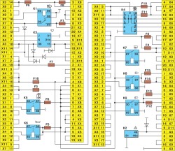
Since 1998, a mounting block 2114-3722010 (in different configurations) with pin headers in different configurations has been installed on VAZ-2108 vehicles. The new mounting block differs from the old one (type 17.3722) in the designation of fuses, relays (see Fig. 7.3b, 7.6b and table 7.1) and connectors (the letter X instead of W), as well as the absence of a rear window washer time relay and an electric motor turn-on relay fan of the engine cooling system. The new mounting block is practically interchangeable with the old one. Specialties are only found in the connection of the headlamp cleaners and the engine cooling fan motor. These features are indicated below in the respective chapters.
Repair of the mounting block consists mainly of replacing printed circuit boards. Soldering of wires is allowed instead of burned-out current-carrying tracks on printed circuit boards, but only if this does not require disconnecting the printed circuit boards.
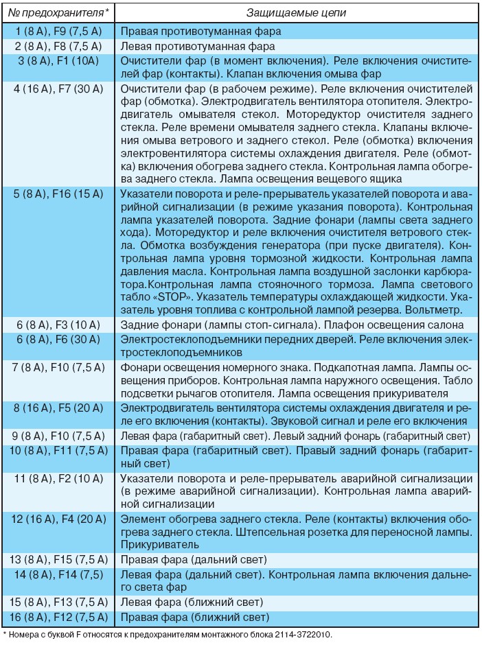
Table 7.1. Fuse-protected circuits
Disassembly and assembly... Disassemble the mounting block for replacement or repair of printed circuit boards in the following order:
Remove the cover and remove the relays, jumpers and fuses from the sockets of the mounting block;
Unscrew the fastening screws and remove the upper half of the mounting block case;
Remove the PCB assembly from the bottom half of the housing.
Assemble the mounting block in the reverse order of disassembly.
The mounting block of a vaz 2109 electrician of the circuit includes all relays and fuses that are responsible for powering the nodes.
It connects the power lines and all the elements of the current distribution circuits are mounted here. The block is a split box, on the inner sides of the covers of which relays, fuses and a board with wiring harness leads are installed.
It should be borne in mind that the ECU for injection engines has a separate wiring.
Basic information about the mounting block
Depending on the year of manufacture and the type of engine, the wiring diagram of the VAZ 2109 is assembled in various versions.
So, on carburetor models, the block layout is presented in a modification of type 17.3722. It contains round fuses that often fail and need to be replaced.
In models with injection engine new equipment was used for the VAZ 2109 wiring block. Now the block has become more reliable due to the installation of new flat-type fuses. Due to their knife design, the flat surface creates a large contact area and they are more reliable.
You can find a new block in the catalog under the marking 2114-3722010-60.
The difference between the VAZ 2109 wiring diagram of these two blocks:
- in the connection of the radiator cooling fan;
- marking of relay connectors and fuses;
- lack of two relays.
Connector and fuse markings
Due to the fact that there is a difference in the marking of the components that make up the wiring diagram of the nodes, you need to know exactly which wiring diagram of the VAZ 2109 is used on the equipment.
- year of manufacture VAZ 2109;
- engine's type;
- type of instrument panel;
- configuration option.
Knowing these initial data, you can find a photo of the circuit on the website of motorists. It is also possible to work with an interactive circuit there, which highlights exactly the desired part of the wiring.
These diagrams indicate the marking of nodes for each type of block. So, if the relay for switching on the cleaners in the old diagram was designated by the number 1, then in the new block it is K1. All nodes are indicated on the diagrams and the specification attached to them. All fuses are marked on the unit body. According to the scheme, the area of responsibility of each product is determined. VAZ 2109 car wiring diagram, the mounting block of which includes plugs for connecting wires, these products are marked with the letter Sh.
How to avoid confusing wires
The multitude of colored wires should not be difficult to troubleshoot with your own hands. The wires have a clear directionality in color:
- yellow - dimensions;
- red - brake light;
- blue - reverse;
- orange-black - anti-fog.
It remains only to select the desired color of the wire and check its serviceability and connect.
Trouble-shooting
The electrical circuit of the mounting block is the main component that ensures the vehicle's performance. If you do not have the necessary skill, it is better to entrust the work of setting up the block to specialists. The cost of repairs will not be commensurate with the cost of transporting a vehicle that has failed along the way. If the repair is done on your own, the repair instructions will help, which can be found on the video in the training programs of the masters.
Dismantling the block
To remove, remove the unit from the installation site, it is necessary to understand that it is an energetic complex unit. Therefore, when disconnecting the electrical wiring, it is necessary to mark the connectors for subsequent collection.

Opening the hood, we find on the left side under the edge windshield a block that is secured with plastic clips. They need to be taken away and the box released. From above it is covered rubber cover that shifts to the side. Having moved the cover, disconnect the block with wires.
After that, the block is freed from the fastening two nuts and rises above the installation site, as far as the wires stretching to it will allow. When disconnecting the wires, mark the connectors so that it is easier to carry out the reverse installation operation later.
Place the removed unit on the work surface and unscrew the lower cover fixing, consisting of 8 bolts. After that, insert a screwdriver into the slot and make a housing connector. The whole scheme will be before your eyes. Examine, compare with the one presented in the instructions and find the place of the malfunction. The help of a specialist is often required at the stage of troubleshooting.
Find:
- violation in payment;
- defective fuse;
- failed relay.
After replacing the part, repairing the damage, the unit is assembled and installed in place in the reverse order. Regardless of the type used in the car electrical circuit blocks are installed the same way.
Typical unit malfunctions
Failure often occurs due to a blown fuse. It is not difficult to find it. You will need to replace it with the same fuse with the same parameters for the current load. It is necessary to find out the reason that led to the operation of the protection. If the problem is not corrected, serious damage may occur.
If the problem occurs in the board, then it may be related to the oxidation of the metal on the circuit. If the contacts are oxidized, they can be cleaned. In this case, the fuses and relays should be removed from the installation sites. The work on cleaning the current leads must be done carefully, and when using a soldering iron to restore the site, all measures are taken to protect the board from accidental damage. Replacing the block will be much easier.
How to work with an electrical block diagram
Using the input data of the VAZ release in the information bases, you should find a diagram of the mounting block of the exact type that is installed on a specific type of car. In this case, two schemes are usually provided. General form the whole block makes it possible to assess the complete similarity of the desired circuit with the existing node.
The second diagram is the wiring inside the block. It is required for detailed study and troubleshooting. At the same time, it is possible to familiarize yourself with an interactive diagram on the site, which will help to track the diagram by elements.
The VAZ 2109 mounting block is designed for combining wiring harnesses, as well as for placing relays and fuses. On the first models, a mounting block of type 17.3722 was used. Consists of a body, consisting of two parts, and a printed circuit board on which leads are soldered to connect to the pads of wiring harnesses, to install relays and fuses. Below is the circuit diagram mounting block VAZ 2109 type 17.3722.
On the latest models, a VAZ 2109 mounting block of type 2114-3722010-60 is used. This unit uses flat blade-type fuses. The contact connection of such fuses is more reliable since they have a large contact area. 
The interchangeability of the connectors of the wiring harness plugs is identical with the block 17.3722. Fuse designations and protected circuits are slightly different. The diagram of the VAZ 2109 mounting block is shown below 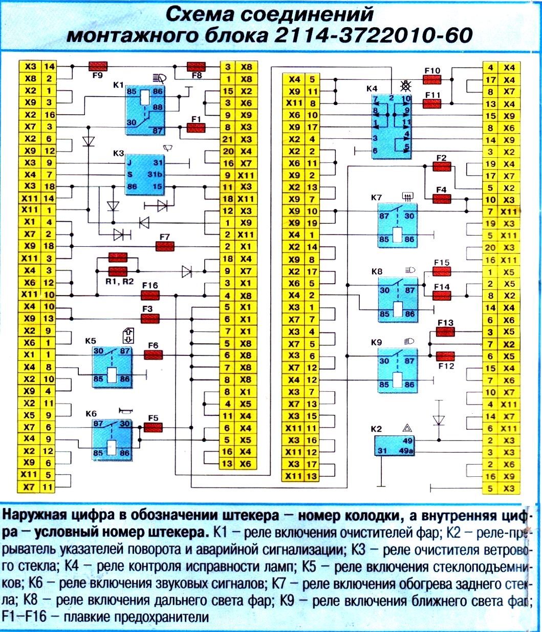
On cars with an injection engine, mounting blocks are used similar to 2114-3722010-60, but they have a different radiator connection.
The location of the mounting block plugs is shown below. 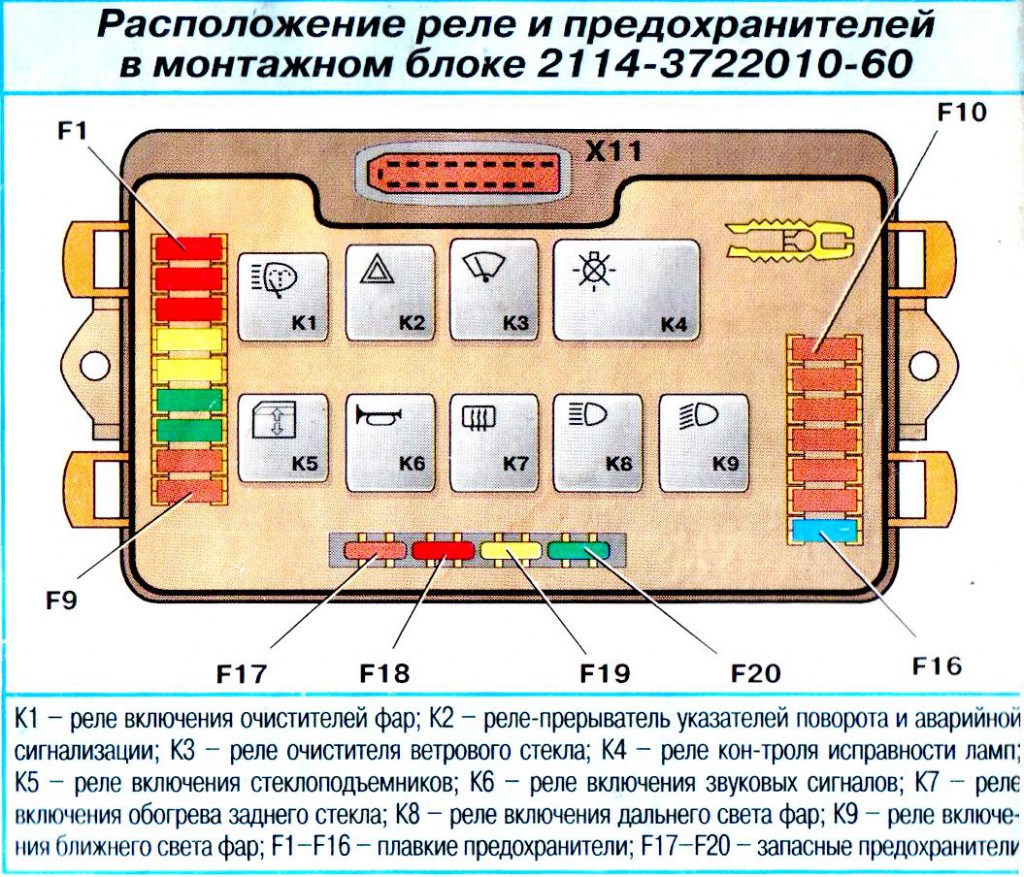
The fuse ratings and circuits to be protected are as follows. * Fuse numbers with the letter F refer to the fuses of the mounting block 2114-3 & 22010-60
| Fuse No. ' | Protected circuits |
| 1 (8 A) F9 (7.5 A) | Right fog lamp |
| 2 (8 A) F8 (7.5 A) | Left fog lamp |
| 3 (8 A) F1 (10 A) | Headlight cleaners (at the moment of switching on). Relay for switching on purifiers headlights (contacts). Headlight washer valve |
| 4 (16 A) F7 (30 A) | Headlight cleaners (in operation). Headlight wiper relay (winding). Heater fan motor. Windshield washer motor. Rear window wiper motor. Rear window washer time relay. Valves for switching on the windscreen and rear window washer. Relay (winding) for turning on the electric fan of the engine cooling system. Relay (winding) for turning on the rear window heating. Control ‘Rear window heating lamp. Glove compartment lamp |
| 5 (8 A) F16 (15 A) | Direction indicators and relay-interrupter for direction indicators and alarm (in direction indication mode). Indicator lamp for direction indicators. Taillights (light bulbs reverse). Gearmotor and relay for switching on the windshield wiper. Excitation winding of the generator (when starting the engine). Level indicator lamp brake fluid... Control lamp for oil pressure. Control lamp for carburetor air damper. Control lamp parking brake... Lamp of the light board "STOR". Coolant temperature gauge. Fuel level indicator with reserve indicator lamp. Voltmeter |
| 6 (8 A) FЗ (10 A) | Rear lights (brake lights). Interior lighting plafond |
| 6 (8 A) F6 (30 A) | Power windows for the front doors. Power window relay |
| 7 (8 A) F10 (7.5 A) | Lanterns of illumination of the license plate. Engine compartment lamp. Instrument lighting lamps. Control lamp for outdoor lighting. Heater levers illumination board. Cigarette lighter lamp |
| 8 (16 A) F5 (20 A) | The electric motor of the fan of the engine cooling system and the relay of its inclusion (contacts). Sound signal and relay to turn it on |
| 9 (8 A) F10 (7.5 A) | Left headlight (side light). Left back light(side light) |
| 10 (8 A) F11 (7.5 A) | Right headlight (side light). Right tail light (side light) |
| 11 (8 A) F2 (10 A) | Direction indicators and alarm relay-interrupter (in alarm mode). Alarm indicator lamp |
| 12 (16 A) F4 (20 A) | Rear window heating element. Relay (contacts) for turning on the rear window heating. Plug socket for portable lamp. Cigarette lighter " |
| 13 (8 A) F15 (7.5 A) | Right headlight (high beam) |
| 14 (8 A) F14 (7.5 A) | Left headlight (high beam). Control lamp of inclusion of a high beam of headlights |
| 15 (8 A) F13 (7.5 A) | Left headlight (low beam) |
| 16 (8 A) F12 (7.5 A) | Right headlight (low beam) |