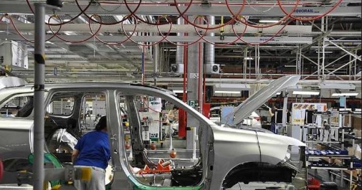
The ZMZ-514 engine and its modifications are intended for installation on passenger cars and utility vehicles. UAZ Patriot, Hunter, Pickup and Cargo. Fuel supply system used Common rail firm "BOSCH", a cooled exhaust gas recirculation system with a throttle pipe, which is also used for soft engine shutdown. To drive the injection pump, water pump and generator, a poly V-belt with an automatic tension mechanism is used.
Diesel engine ZMZ 51432.10 euro 4
Engine characteristics ZMZ-51432.10
| Parameter | Meaning |
|---|---|
| Configuration | L |
| Number of cylinders | 4 |
| Volume, l | 2,235 |
| Cylinder diameter, mm | 87 |
| Piston stroke, mm | 94 |
| Compression ratio | 19 |
| Number of valves per cylinder | 4 (2-inlet; 2-outlet) |
| Gas distribution mechanism | DOHC |
| The order of the cylinders | 1-3-4-2 |
| Engine rated power / at speed crankshaft | 83.5 kW - (113.5 HP) / 3500 rpm |
| Maximum torque / at engine speed | 270 N m / 1300-2800 rpm |
| Supply system | with direct injection, turbocharging and charge air cooling |
| Environmental standards | Euro 4 |
| Weight, kg | 220 |
Engine design
Four-stroke engine with an electronically controlled Common Rail fuel supply system, in-line cylinders and pistons rotating one common crankshaft, with an overhead arrangement of two camshafts... The engine has a closed-type forced circulation liquid cooling system. Combined lubrication system: pressure and spray. Cylinder block The ZMZ-514 cylinder block is made of special cast iron as a monoblock with a crankcase part lowered below the crankshaft axis. Crankshaft The ZMZ-514 crankshaft is forged steel, five-bearing, has eight counterweights for better unloading of the supports.| Parameter | Meaning |
|---|---|
| Diameter of the main journals, mm | 62,00 |
| Diameter of connecting rod journals, mm | 56,00 |
Diesel engine modifications ZMZ 514

ZMZ 5143
ZMZ 514.10 euro 2 with mechanical injection pump Bosch VE. Without intercooler and alternator vacuum pump. They put on the UAZ Hunter and Patriot. Power 98 HP

Engine problems
Early versions of the ZMZ-514 engine suffered from factory miscalculations that "got out" during operation. Forum users collected and classified the failures of the ZMZ-514 diesel engine: 1. Cracked cylinder head. It was noted on engines until 2008. Signs: coolant leaving the engine crankcase, gas breakthrough, emulsion on the dipstick. The reason is casting defect, airing of the cooling system, violation of broaching technology. Since 2008, the cylinder head installed on the conveyor has not been defect. Repair: replacement of the cylinder head with a modern casting. Prevention for the cylinder head from the "risk zone": 1) changing the coolant compensation for a system with valves in the expansion tank plug with its rise above the radiator level. 2) Selection of engine operating modes without long-term loads over 3000 rpm. (If it seems small to anyone, then, for example, on 245/75 tires in 5th gear of daimos at a speed of 110 km / h, rpm 2900). 3) Checking the cylinder head broach on engines 7-8 years of production. links: secret letter from ZMZ to service station Expansion tank, alteration 2. Jump / break of the timing chain. Possible on all motors. Signs: Abrupt stop of the engine. The engine will not start. Timing marks misalignment. Reason: the outdated design of the hydraulic tensioner does not provide reliability. Poor quality third-party part. Repair: Replacing broken valve levers. Correction of timing marks. In the event of an open circuit, troubleshooting and replacement of the failed drive parts. Prevention: 1) control of the condition of the chain tension through the oil filler neck. 2) replacement of hydraulic tensioners with a design that ensures reliability. Links: about hydraulic tensioners replacement of hydraulic tensioners On EURO4 engines: the design has not changed. 3. Failure of the oil pump drive. Typical on Euro3 engines with a vacuum pump on the engine block. Since the end of the 10th year has not been observed. Signs: drop in oil pressure to 0. Cause: poor quality gear material. Increased drive load due to jamming of the vacuum pump. Repair: replacement of oil pump drive gears with revision of oil pump and vacuum pump. In the case of engine operation without oil pressure, detailed troubleshooting and, if necessary, more complex repairs. Prevention: oil pressure control. Check the oil supply hose to the vacuum pump for kinks. Checking the vacuum pump for wedging. If necessary, elimination of found defects. On EURO4 engines: a modified vacuum pump is located on the front cylinder head cover. Vacuum pump drive directly from the top chain. Structurally, there is no additional load on the oil pump drive. 4. Entry of the SROG valve disc into the engine cylinder. Signs: Black smoke, blow / bumps in the engine area, triplet, not starting. Reason: not a high-quality part of a third-party manufacturer, burning of the SROG valve disc from the stem, the passage of the disc through the intake pipe into the engine cylinder. Repair: Replacement of failed parts, depending on the degree of damage: piston, valve, cylinder head. Prevention: Shutdown of the SROG valve with shutdown of the system. On EURO4 motors: srog valve made in germanium with electronic control provisions with a set resource until 80,000 km are replaced. 5. Unscrewing the plug KV. Signs: a decrease in oil pressure, depending on the situation, the breakdown of the block. Reason: KV plugs are not locked or not properly locked. Repair: installation and locking of plugs, depending on the consequences, repair or replacement of the engine block. Prevention: Oil pressure control. Removing the engine sump with monitoring the condition of the plugs, if necessary, broaching and locking by punching. On EURO4 motors: On changing the quality control of work on the conveyor in better side unknown. 6.1 Jumping of the injection pump drive belt. Signs: reduced smoke draft, up to jamming and non-start. Reason: getting dirt on the KV pulley, loosening the belt tension. Repair: setting the belt according to the marks. Prevention: compliance with the regulation of belt tension control and replacement requirements. On EURO4 motors: injection pump drive by poly-V-belt with automatic tensioner. 6.2 Lateral wear of the injection pump drive belt, belt breakage at extreme wear. Marked on Euro2 motors. Signs: Tendency for the belt to slip off the high-pressure pump pulley, wear of the sidewall by the tension roller, grazing the belt over the casing. In the event of a break, spontaneous engine shutdown. Reason: tilting of the roller due to unreliable construction and wear on the roller mounting axis. Repair: replacement of the belt and tension roller, reversal of the roller axis. Replacing the roller with a fixed design. Prevention: at the time of regulation, the replacement of the roller with a fixed structure. On EURO3 motors: modified design tensioner with eccentric tension. On EURO4 motors: poly-V-belt with automatic tensioner. 7. Breakage of the high pressure pipeline from the injection pump to the nozzle. It was noted on engines EURO2 2006-partly 2007. Most often on a 4 cylinder. Sign: sudden tripping of the engine, smell of diesel fuel. Reason: Incorrect choice of tube bending angles when designing non-compensating loads. Incorrect installation in an interference fit. Solution: replacement of tubes with a new sample produced since 2007. Prophylaxis for old pipes (it will not interfere with new ones): when removing and installing pipes, do not allow tightening into an interference fit. First, we press the tube against the nozzle seat, then screw on the nut and stretch it out. Do not allow the pipelines to touch each other. Correctly select the central position of the injection pump before mounting and adjusting the injection. Fuel from the right fuel tank 12 through a coarse fuel filter 11 is supplied by an electric fuel pump 10 under pressure to a fine fuel filter 8 (FTOT). When the pressure of the fuel supplied by the electric pump is more than 60-80 KPa (0.6-0.8 kgf / cm2), the bypass valve 17 opens, diverting excess fuel into the drain line 16. The cleaned fuel from the FTOT enters the high-pressure fuel pump (HPP) 5. Further, the fuel is supplied using the high pressure fuel pump distributor plunger in accordance with the order of operation of the cylinders through the high pressure fuel lines 3 to the injectors 2, with the help of which fuel is injected into the diesel combustion chamber. Excess fuel, as well as air that has entered the system, are discharged from the injectors, high-pressure fuel pump and bypass valve through the fuel lines to drain the fuel into the tanks
Diagram of the power supply system of the ZMZ-514.10 and 5143.10 diesel engine on UAZ vehicles with an electric fuel pump:
1 - engine; 2 - nozzles; 3 - high pressure fuel lines of the engine; 4 - hose for removing cutoff fuel from injectors to high pressure fuel pump; 5 - injection pump; 6 - fuel supply hose from FTOT to high pressure fuel pump; 7 - fuel drain hose from the injection pump to the FTOT fitting; 8 - FTOT; 9 - fuel line for taking fuel from the tanks; 10 - electric fuel pump; 11 - coarse fuel filter; 12 - right fuel tank; 13 - left fuel tank; 14 - fuel tank valve; 15 - jet pump; 16 - fuel line for draining fuel into tanks; 17 - bypass valve. High pressure fuel pump (TNVD) ZMZ-514.10 and 5143.10 distribution type with built-in fuel priming pump, boost corrector and solenoid valve for fuel shut-off. The injection pump is equipped with a two-mode mechanical crankshaft speed controller. The main function of the pump is the supply of fuel to the engine cylinders under high pressure, metered according to the engine load at a certain point in time, depending on the crankshaft speed.

Fuel pump high pressure BOSCH type VE.
1 - solenoid valve for stopping the engine; 2 - screw for adjusting maximum speed idle move; 3 - adjusting screw for maximum fuel supply (sealed and not adjustable during operation); 4 - fitting of the air boost corrector; 5 - air boost corrector; 6 - screw for adjusting the minimum idle speed; 7 - unions of high pressure fuel lines; 8 - high pressure fuel pump mounting bracket; 9 - high pressure fuel pump mounting flange; 10 - opening of the injection pump housing for installing the centralizer pin; 11 - groove in the hub for the centralizer pin of the injection pump; 12 - high-pressure fuel pump pulley hub; 13 - fuel inlet union; 14 - fuel supply lever; 15 - fuel supply lever position sensor; 16 - sensor connector; 17 - connection for supplying cut-off fuel from injectors; 18 - nozzle for fuel outlet to the drain line; 19 - nut for fastening the hub on the injection pump shaft Nozzle closed, with two-stage fuel supply. Injection pressure: - first stage (stage) - 19.7 MPa (197 kgf / cm 2) - second stage (stage) - 30.9 MPa (309 kgf / cm 2) Fine filter fuel (FTOT) is essential for the normal and trouble-free operation of the injection pump and injectors. Since the plunger, sleeve, discharge valve and nozzle elements are precision parts, fuel filter should retain the smallest abrasive particles 3 ... 5 microns in size. An important function of the filter is also the retention and separation of water contained in the fuel. The ingress of moisture into the inner space of the injection pump can lead to the failure of the latter due to the formation of corrosion and wear of the plunger pair. The water trapped by the filter is collected in the filter sump, from where it must be periodically removed through the drain plug. Drain sediment from FTOT every 5,000 km of vehicle mileage. Bypass valve ball type is screwed into the fitting, which is installed on the fine fuel filter. The bypass valve is designed to bypass excess fuel supplied by the electric fuel pump to the fuel drain line to the tanks. The design of the ZMZ-514 engine


crank mechanism
Cylinder block made of special cast iron in a monoblock with a crankcase part lowered below the crankshaft axis. There are coolant passages between the cylinders. In the lower part of the block, there are five main bearing supports. The bearing caps are machined with the cylinder block and are therefore not interchangeable. In the crankcase part of the cylinder block, nozzles are installed to cool the pistons with oil. Cylinder head cast from an aluminum alloy. In the upper part of the cylinder head there is a gas distribution mechanism: camshafts, valve drive levers, hydraulic supports, intake and exhaust valves. The cylinder head has two intake ports and two exhaust ports, flanges for connecting the intake pipe, exhaust manifold, thermostat, covers, seats for injectors and glow plugs, built-in elements of cooling and lubrication systems. Piston cast from a special aluminum alloy, with a combustion chamber made in the piston head. Combustion chamber volume (21.69 ± 0.4) cm3. The piston skirt is barrel-shaped in the longitudinal direction and oval in cross-section, has an anti-friction coating. The major axis of the oval is located in a plane perpendicular to the axis of the piston pin. The largest diameter of the piston skirt in longitudinal section is located at a distance of 13 mm from the lower edge of the piston. A recess is made at the bottom of the skirt, which allows the piston to diverge from the cooling nozzle. Piston rings installed on three on each piston: two compression and one oil scraper. The upper compression ring is made of ductile iron and has an equilateral trapezoidal shape and a wear-resistant anti-friction coating on the surface facing the cylinder bore. The lower compression ring is made of gray cast iron, rectangular profile, with a minute bevel, with a wear-resistant anti-friction coating of the surface facing the cylinder mirror. The oil scraper ring is made of gray cast iron, box-type, with a spring expander, with a wear-resistant anti-friction coating of the working belts of the surface facing the cylinder mirror. Connecting rod- steel forged. The connecting rod cover is machined together with the connecting rod, and therefore, when the engine is overhauled, the covers cannot be rearranged from one connecting rod to another. The connecting rod cover is secured with bolts that are screwed into the connecting rod. A steel-bronze bushing is pressed into the piston head of the connecting rod. Crankshaft- forged steel, five-bearing, has eight counterweights for better unloading of the supports. The wear resistance of the necks is ensured by HFC hardening or gas nitriding. The threaded plugs covering the channel cavities in the connecting rod journals are placed on the sealant and are coined against self-unscrewing. The shaft is dynamically balanced, the permissible unbalance at each end of the shaft is not more than 18 g · cm. Earbuds main bearings of the crankshaft - steel-aluminum. Upper bushings with grooves and holes, lower ones without grooves and holes. The connecting rod bearing shells are steel-bronze, without grooves and holes. Pulley damper consists of two pulleys: toothed 2 - to drive the injection pump and poly-V 3 - to drive the water pump and generator, as well as rotor 4 of the crankshaft position sensor and damper disc 5. The damper serves to damp torsional vibrations of the crankshaft, thereby ensuring the uniformity of the injection pump , the operating conditions of the camshaft chain drive are improved and the timing noise is reduced. The damper disk 5 is vulkonized to the pulley 2. There is a round mark on the surface of the sensor rotor for determining the TDC of the first cylinder. The operation of the crankshaft position sensor consists in the formation and transmission of pulses to the electronic control unit from the grooves located on the outer surface of the rotor. The front end of the crankshaft is sealed with a rubber cuff 7 pressed into the chain cover 6.
Gas distribution mechanism
Camshafts made of low-carbon alloy steel, cemented to a depth of 1.3 ... 1.8 mm and hardened to a hardness of working surfaces of 59 ... 65 HRCE. The engine has two camshafts: to drive the intake and exhaust valves. Shaft cams are multi-profile, asymmetric relative to the cam axis. At the rear ends, the camshafts are marked with branding: inlet - "VP", outlet - "VEP". Each shaft has five bearing journals. The shafts rotate in bearings located in the aluminum cylinder head and covered with covers bored 22 together with the head. For this reason, the camshaft bearing caps are not interchangeable. Each camshaft is held against axial movements by a thrust washer, which is installed in the groove of the front support cover and as a protruding part enters the groove on the first bearing journal of the camshaft. The front end of the camshafts has a tapered surface for the drive sprocket. To accurately set the valve timing, a technological hole is made in the first journal of each camshaft with a precisely defined angular position relative to the cam profile. When assembling the camshaft drive, their exact position is ensured by clips that are installed through the holes in the front cover into the technological holes on the first camshaft journals. Technological holes are also used to control the angular position of the cams (valve timing) during engine operation. The first transition journal of the camshaft has two flats with a wrench size to hold the camshaft when attaching the sprocket. Camshaft drive chain, two-stage. The first stage is from the crankshaft to the intermediate shaft, the second stage is from the intermediate shaft to the camshafts. The drive provides a camshaft speed that is half the speed of the crankshaft. The drive chain of the first stage (lower) has 72 links, the second stage (upper) has 82 links. Bush chain, double row with a pitch of 9.525 mm. At the front end of the crankshaft, a sprocket 1 made of nodular cast iron with 23 teeth is mounted on a key. A driven sprocket 5 of the first stage also made of ductile iron with 38 teeth and a driving steel sprocket 6 of the second stage with 19 teeth are simultaneously fixed on the intermediate shaft with two bolts. On camshafts Installed sprockets 9 and 12 made of nodular cast iron with 23 teeth


Lubrication system
The lubrication system is combined, multifunctional: pressure and spray. It is used to cool the pistons and bearings of the turbocharger, the oil under pressure brings the hydraulic bearings and hydraulic tensioners into working condition.
Crankcase ventilation system
Crankcase ventilation system- closed type, acting due to rarefaction in intake system... Oil baffle 4 is located in the oil separator cover 3.
Cooling system
Cooling system- liquid, closed, with forced circulation of the coolant. The system includes water jackets in the cylinder block and in the cylinder head, water pump, thermostat, radiator, liquid-oil heat exchanger, expansion tank with a special plug, fan with clutch, coolant drain valves on the cylinder block and radiator, sensors: coolant temperature (control system), coolant temperature gauge, coolant overheat indicator. The most advantageous temperature regime of the coolant lies in the range of 80 ... 90 ° C. The indicated temperature is maintained by an automatic thermostat. Maintaining the correct thermostat temperature regime in the cooling system has a decisive effect on the wear of engine parts and the efficiency of its operation. To control the temperature of the coolant in the instrument cluster of the car there is a temperature gauge, the sensor of which is screwed into the thermostat housing. In addition, there is an emergency temperature indicator in the instrument cluster of the car, which lights up in red when the liquid temperature rises above + 102 ... 109 ° С. Water pump centrifugal type is located and fixed on the chain cover. Water pump drive and the generator is carried out by a 6PK 1220 poly V-belt. The belt is tensioned by changing the position of the tension roller / Power steering fan and pump drive it is carried out by a poly-V-belt 6RK 925. The belt is tensioned by changing the position of the power steering pump pulley.

Air intake and exhaust system
The ZMZ-5143.10 engines use a four-valve one-cylinder gas distribution system, which significantly improves the filling and cleaning of cylinders in comparison with a two-valve one, as well as, in conjunction with the screw shape of the inlet channels, to provide a vortex movement of the air charge for better mixture formation. Air intake system includes: air filter, hose, turbocharger inlet pipe, turbocharger 5, turbocharger outlet (discharge) pipe 4, air duct 3, receiver 2, inlet pipe 1, cylinder head inlets, intake valves. The air is supplied at engine start-up by means of a vacuum generated by the pistons and then by a turbocharger with variable charging.

Exhaust Gas Recirculation System (SROG)
The exhaust gas recirculation system is used to reduce the emission of toxic substances (NOx) with the exhaust gases by supplying part of the exhaust gases (exhaust gas) from the exhaust manifold to the engine cylinders. The recirculation of exhaust gases on the engine begins after the coolant has warmed up to a temperature of 20 ... 23 ° C and is carried out in the entire range of partial loads. When the engine is running at full load, the EGR is deactivated.
Engine Management System
The engine control system is designed to start the engine, control it in driving mode vehicle and stops. Main functions of the engine management system ➤ The main functions of this system are:- Glow plug control - to ensure a cold start of the engine and its warming up; - Exhaust gas recirculation control - to reduce the content of nitrogen oxides (NOx) in the exhaust gases; - control of the operation of the electric booster pump (ESP) - to improve the fuel supply; - generating a signal to the car's tachometer - to provide information about the speed of rotation of the engine crankshaft.
Engines ZMZ-514 are designed for installation on UAZ vehicles with 4x4 wheel arrangement and full weight up to 3,500 kg and operation at ambient temperatures from minus 45 ° C to plus 40 ° C, relative air humidity up to 75% at a temperature of plus 15 ° C, dust content up to 1 g / m 3, as well as in areas located on altitude up to 4000 m above sea level.
At the moment (2016) in the line of diesel ZMZ engines there are two models: ZMZ-5143.10 with mechanical injection pump and ZMZ-51432.10 CRS Common Rail fuel supply system
Engine appearance ZMZ-5143.10:
Engine appearance ZMZ-51432.10 CRS
Engine history
The history of the diesel engine at ZMZ began in 1978, when the GAZ plant gave ZMZ an assignment to design a new family of E403.10 engines for the promising Volga. The program also included a 2.3-liter turbodiesel with a cast iron cylinder block. Estimated power - 80–90 liters. with. But then it did not come to a diesel engine.
402.10.
1982 - 1984 work was carried out to create a diesel engine for a Volga passenger car with a working volume of 2.45 dm3, a maximum power of 50 kW (68 hp) at a crankshaft speed of 4500 min-1 with a minimum specific consumption of 251.6 g / kWh (185 g / hp-h). The engine was designed with a die-cast aluminum cylinder block. To obtain a "soft" working process, a vortex chamber combustion process was used; to ensure the reliability of the cylinder-piston group, anchor pins were used, pulling the cylinder head, cylinder block and crankshaft bearings into a single package. The piston is made of an aluminum alloy with a special micro-relief and a barrel-shaped skirt profile. The compression ratio of the engine is 20.5, the fuel pump is driven from the camshaft gear. The design of the engine provided for jet cooling of the pistons, an indicator of clogging of the oil filter, a candle preheating.
The prototype of the engine has passed laboratory and road tests, including at the NAMI auto-range as part of the GAZ-24 "Volga" passenger car.
However, in connection with the decision taken at that time by the Ministry of Automotive Industry to reorient the Ulyanovsk Motor Plant to organize the production of small-displacement diesel engines with the simultaneous development of diesel fuel equipment, further work at ZMZ was stopped.
Diesel engine based on ZMZ406.10.
In 1992, the plant mastered a new gasoline engine ZMZ-406.10. Simultaneously with the introduction of gasoline engines on the carpet, they began to create a turbodiesel based on them.
Based on preliminary studies and the desire to have maximum unification with the base engine ZMZ-406.10, it was decided to reduce the cylinder diameter to 86 mm. This was achieved by installing a dry thin-walled sleeve in a cast-iron monoblock; at the same time, it was possible to maintain the dimensions of the main and connecting rod bearings of the base engine and, accordingly, have almost complete unification in the processing of the cylinder block and the crankshaft.
Provided for the use of turbocharging and charge air cooling
In November 1995, the first sample of a 105-horsepower diesel engine 406D.10 was manufactured and assembled.
Diesel engine prototype ZMZ-406D.10 in the Experimental workshop. December 1995: 
When designing, the following engine indicators were taken:
At the Yaroslavl plant of diesel equipment (YAZDA) according to technical requirements ZMZ developed and manufactured a small-sized multi-nozzle fuel injector, which made it possible to resolve issues of fine-tuning the working process only with domestic manufacturers.
Diesel engine ZMZ-406D.10 in the Experimental workshop of the UGK: 
Tests ZMZ-406D. 10. April 1998: 
Cross section of the ZMZ-406D.10 engine 
External view of ZMZ-406D.10 
Appearance of the first ZMZ-406D.10:

For further refinement, the new engine was sent to England to the specialists of the Ricardo firm.
The British advised to change the design of the cylinder head, which was with a V-shaped valve arrangement. The head was redesigned: the shape of the combustion chamber was changed, the valves were placed vertically.


In 2002, the engine was demonstrated in Moscow at the Moscow Motor Show:


But due to the unstable quality of components and the technological complexity of processing parts at the plant itself, serial production was curtailed by the beginning of 2004.
However, work on the completion of the new engine continued. The design of the head and block has changed, as a result of which their rigidity has increased. To better seal the gas joint, instead of the domestic flexible cylinder head gasket, they began to use imported multilayer metal. The revision and manufacture of pistons was entrusted to the German company Mahle. Changes that increase reliability and service life also affected connecting rods, timing chains and a number of small parts. As a result, in November 2005, the production of diesel engines under the index ZMZ-5143.
Design ZMZ-5143 is that.
The cylinder head is made of aluminum alloy. The vertical valves are driven by two camshafts via single-arm needle-bearing roller levers. Valve mechanism with the German INA hydraulic support.
The camshaft drive is a chain, two-stage, similar to the ZMZ-406. However, the length of the chains is different, and instead of the plastic levers, an asterisk was used for tensioning, which, in the order of reverse unification, was also introduced on gasoline engines... Chain tensioners are hydraulic.
Cylinder block made of special cast iron. The casting is unified with the ZMZ-406 gasoline block. The cylinder diameter is 87 mm, the piston stroke is 94 mm (for the gasoline "406" engine - 92x86 mm). In the crankcase of the block there are special nozzles through which the oil coming from the central line cools the pistons.
The crankshaft is original, forged steel with a crank radius of 47 mm - the forging is made by KamAZ. The shaft is hardened by high frequency quenching or nitriding of the outer surface.
The piston with a combustion chamber in the bottom is made of an aluminum alloy with a ni-resist insert for a compression ring; the skirt is treated with Molikot anti-friction compound. The piston rings are from Götze.
Fuel equipment "Bosch". High pressure fuel pump with mechanical regulator. Especially for the ZMZ-514, Bosch has modified its VE-type distribution pump, which now develops a maximum pressure of 1100 bar and has correctors for boosting and for warming up the engine in winter. The high-pressure fuel pump is driven from the crankshaft by a VAZ 2112 toothed belt, closed with a protective casing.
Bosch injectors - two-spring, allow preliminary injection of fuel. Fine fuel filter with hand pump, heater, water separator - "Boshevsky", high pressure fuel lines - "Guido".
The turbocharger is Czech, manufactured by ČZ-Strakonice AS, also adapted by Garrett, which has a higher efficiency.
Since 2006, these motors have been serially installed on UAZ Hunter.
In 2007, ZMZ-514 was adapted for installation on UAZ commercial vehicles.
In 2012, the production of ZMZ-51432.10 CRS with a Common Rail fuel supply system that meets the environmental requirements of Euro-4 was mastered. These engines are installed on cars and utility vehicles UAZ Patriot, Hunter, Pickup and Cargo.
Engine markings
The ZMZ-514.10 engine family is a 4-cylinder 16-valve diesel engine with a working volume of 2.24 liters.
| Engine designation by CD | VDS-descriptive part of marking | Characteristics completeness and version of the engine | Applicability on a car |
| Complete set with a high pressure fuel pump VE 4 / 11F 2100RV | |||
| 514.1000400 | 51400 | Basic complete set in a single version with a high-pressure fuel pump VE 4 / 11F 2100RV, without power steering and fan drive. | |
| 514.1000400-10 | 51400A | Basic complete set in a single version with clutch housing, SROG, power steering, without fan | cars of OJSC "GAZ" |
| 514.1000400-20 | 51400B | Basic complete set in a single version with a high-pressure fuel pump VE 4 / 11F 2100RV, with a power steering and a fan drive, an oil sump of the ZMZ-5141 engine, with oil filter reduced dimensions. | |
| 5141.1000400 | 514100 | Completeness in a single version with a high-pressure fuel pump VE 4 / 11F 2100RV, power steering, air conditioning, without a fan. | |
| 5143.1000400 | 514300 | Basic complete set in a single version with a high-pressure fuel pump VE 4 / 11F 2100RV, power steering. | |
| 5143.1000400-10 | 51430A | Completeness in a single version with a high-pressure fuel pump VE 4 / 11F 2100RV, power steering, air conditioning. | |
| 5143.1000400-20 | 51430V | Completeness in a single version with a VE 4 / 11F 2100RV high-pressure fuel pump, a fan drive and power steering pump brackets. | |
| 5143.1000400-30 | 51430C | Completeness in a single version with a high-pressure fuel pump VE 4 / 11F 2100RV, a fan drive and power steering brackets, with fuel supply lines changed, compared to basic configuration, long. | |
| 5143.1000400-40 | 51430D | Completeness in a single version with a fan drive, a vacuum pump combined with a generator, clutch housing, SROG, power steering | UAZ-315148 "Hunter" |
| 5143.1000400-41 | 51430G | Completeness in a single version with a fan drive, a vacuum pump on the cylinder block, SROG, power steering, without clutch housing | UAZ-315148 "Hunter" |
| 5143.1000400-42 | 51430H | Completeness in a single version with a fan drive, a vacuum pump on the cylinder block, SROG, a branch pipe for connecting an autonomous heater-heater, power steering, without a clutch housing | UAZ-296608 |
| 5143.1000400-50 | 51430E | Complete set in a single version with a high-pressure fuel pump VE 4 / 11F 2100RV, a fan drive and power steering pump brackets, without a fuel pump, with a bypass valve on the fine fuel filter. | |
| 5143.1000400-80 | 51430L | Completeness in a single version with a fan drive, a vacuum pump on the cylinder block, SROG, a recirculated exhaust gas cooler, power steering, without a clutch housing | |
| 5143.1000400-81 | 51430M | Completeness in a single version with a fan drive, a vacuum pump on the cylinder block, SROG, a recirculated exhaust gas cooler, a branch pipe for connecting an autonomous heater-heater, power steering, without a clutch housing | UAZ-315148 "Hunter" environmental class 3 |
| 5143.1000400-43 | 51430R | Completeness in a single version with a fan drive, a vacuum pump on the cylinder block, a branch pipe for connecting an autonomous heater-heater, power steering, without clutch housing, without SROG | UAZ-315108 "Hunter" for MO) |
| 5143.1000400-60 | 51430S | Completeness in a single design with a fan drive, a vacuum pump on the cylinder block, a branch pipe for connecting an autonomous heater-heater, a clutch housing, a small-sized oil filter, power steering, without SROG | UAZ-396218 ("Loaf" - an off-road ambulance vehicle for the Ministry of Defense) |
| Complete set of diesel engines ZMZ-51432 for UAZ vehicles of environmental class 4 (Euro4) | |||
| 51432.1000400 | 51432A | Without clutch housing for DYMOS gearbox; SANDEN air conditioner compressor; power steering pump Delphi; generator 120A | |
| 51432.1000400-01 | 51432B | Without clutch housing for DYMOS gearbox; SANDEN air conditioner compressor; power steering pump Delphi; generator 120A; branch pipe 40624.1148010 for connecting an autonomous heater. | UAZ-31638 "Patriot", UAZ-31648 "Patriot Sport", UAZ-23638 "Pickup", UAZ-23608 "Cargo" |
| 51432.1000400-10 | 51432C | Without clutch housing for DYMOS gearbox; power steering pump Delphi; alternator 80 A or 90 A. | UAZ-31638 "Patriot", UAZ-31648 "Patriot Sport", UAZ-23638 "Pickup", UAZ-23608 "Cargo" |
| 51432.1000400-20 | 51432D | Without clutch housing for DYMOS gearbox; power steering pump; alternator 80 A or 90 A. | UAZ-315148 "Hunter" |
| 51432.1000400-21 | 51432E | Without clutch housing for DYMOS gearbox; power steering pump; generator 80 A or 90 A; branch pipe 40624.1148010 for connecting an autonomous heater. | UAZ-315148 "Hunter" |
| 51432.1000400-22 | 51432F | with clutch housing under 5 stepped gearbox ADS; power steering pump; alternator 80 A or 90 A. | UAZ-315148 "Hunter" |
| 51432.1000400-23 | 51432G | with clutch housing for 5-speed gearbox ADS; power steering pump; generator 80 A or 90 A; branch pipe 40624.1148010 for connecting an autonomous heater | UAZ-315148 "Hunter" |
"ZMZ-514" is a family of four-cylinder sixteen-valve engines with 4-working volume of 2.24 liters. Initially, these motors were intended for use in passenger cars and commercial vehicles GA3, however, in the end they found their application on the UA3ax. Diesel engines "3M3-514" were installed on "GA3el" only from 2002 to 2004, in a rather limited number. Since 2006, the Ulyanovsk Automobile Plant has become a consumer of these power units: they "took root" first on the UA3 Hunter off-road vehicles, and then on the Patriots, and the UA3 Cargo created on their basis. But - only for a few years: in 2015, the Ulyanovsk Automobile Plant finally abandoned the use of motors of the 3M3-514 family. What are the reasons, and what are the features of this family - read on.
The main reason for the rejection of the diesel modifications of the Patriot and Hunter is the negligible demand for these machines. Not only do UAZs themselves do not shine with gigantic sales volumes, but also the demand for diesel complete sets of Ulyanovsk SUVs turned out to be too small to be considered promising models. According to the company's management, sales of diesel "Patriots" accounted for only 1% (!) Of the total number of cars sold.
It would seem that for such cars as UAZ SUVs, diesel engines are simply "asked for". After all, it promises serious advantages: even more serious and stable off-road cross-country ability, the ability to load the car and the trailer to the maximum, fuel efficiency, high engine efficiency ... , compared to gasoline. The entire torque, equal to 270 N * m, the diesel power unit produces already in the range from 1300 rpm to 2800 rpm; the diesel is lighter and calmer "drags" not the lightest body of the UAZ. All these are the main indicators of utilitarianism. And utility for a jeep or a pickup is above all. Those car enthusiasts who had to drive both gasoline and diesel "Patriots" noted that diesel engines differ significantly for the better from gasoline ones.
However, despite all the alterations and improvements, the "3M3-514" "remained an unreliable and capricious engine. Common, frequently occurring problems with timing drives and high-pressure fuel pumps, short service life of the oil pump, bursts fuel line Injection pump, cases of a sharp decrease in thrust, the entry of the SROG valve plate into the engine cylinder, unscrewing the KV plug, and even such an outrage as the cracks in the cylinder head that formed after 40 thousand kilometers (casting defect), according to the manufacturer, were eliminated. But many "UAZovodov" had a different opinion on this matter.
After equipping new version engine - "3M3-514Z2.10 CRS" - fuel equipment for electronic control of injection Bosch Common Rail The engine has become less maintainable, and if repairable, then only immediately by units that are not cheap, as well as more demanding on the quality of diesel fuel. Problems with direct injection, constant metamorphoses with fuel pressure, were added to the problems indicated earlier.
During the modernization, Bosch nozzles and injection pumps, a ramp, glow plugs were added to the motor; supplemented this with a Chinese turbocharger, and the engine still does not shine with either reliability or durability in use. Of course, this reputation was bad for sales. In addition, the price of the diesel UAZ Patriot was more than 100 thousand more than the gasoline version of this model.

The 3M3-514 family traces its history back to the early 1980s, when the Zavolzhsky Motor Plant began work on the creation of a diesel engine based on a conventional carburetor engine for the Volga - 3M3-402.10. By 1984, a prototype of this power unit laboratory and road tests were created and passed, including at the NAMI auto-range as part of the light car GA3-24 "Volga". Working volume - 2.45 liters, compression ratio - 20.5; with an aluminum block of cylinders, pistons made of aluminum alloy with a special micro-relief and a barrel-shaped skirt profile, jet cooling of the pistons, a clogged oil filter indicator, a glow plug. However, this model was not continued.
Only in the first half of the 90s, the specialists of the Zavolzhsky Motor Plant returned to creating their own diesel engine for cars and light trucks. For some reason, they were given the task of making a diesel engine not just based on the gasoline "3M3-406.10", but also having the maximum unification with this basic power unit.
Based on preliminary developments and the desire to ensure maximum unification with the base engine "3M3-406.10", the cylinder diameter was reduced to 86 mm. This was achieved by installing a dry thin-walled sleeve in a cast-iron monoblock; while maintaining the dimensions of the main and connecting rod bearings of the base engine and, therefore, almost complete unification in the processing of the cylinder block and the crankshaft. From the very beginning, the new diesel engine provided for the use of turbocharging, with charge air cooling.
The first sample of the future "3M3-514", under the name "3M3-406.10", was made in November 1995. At the Yaroslavl Diesel Equipment Plant (YAZDA), according to the technical requirements of the Zavolzhsky Motor Plant, a small-sized, multi-nozzle fuel injector was developed and manufactured. In the end, it was decided to make the cylinder head not from cast iron, but from aluminum.

In December 1999, the first pilot batch of diesel engines "3M3-514" - 10 units was manufactured. In 2002, they made their debut at GAZelles. However, during the first two years, even the very first year of operation, it turned out that there were difficulties with servicing these engines, and their reliability did not stand up to criticism.
According to experts, the archaic production equipment of the Zavolzhsky Motor Company lacked the capacity to ensure the required quality of the metal and maintain the accuracy of machining of auto parts. The diesel engine, unlike the gasoline engine, did not tolerate this. In addition, component suppliers have contributed their "fly in the ointment" to the growth of the substandard flow. And then the unstable quality sharply scared off buyers, who at first cheerfully reacted to the idea of replacing the carburetor engines with a modern economical turbodiesel. As a result, by the beginning of 2004, the serial production of diesel engines for 3M3 was curtailed, in fact, and did not begin.
Nevertheless, the revision and refinement of the "3M3-514" continued. Changed the design of the head and block, with an increase in their rigidity. For a better sealing of the gas joint, instead of the domestic flexible cylinder head gasket, an imported multilayer, metal one was used. The revision and manufacture of pistons was entrusted to the German company "Mahle". Changed, in order to improve reliability and resource, were the connecting rods, timing chains and a number of small parts.
The result of this was the launch of the 3M3-514Z modification into serial production, and since 2006, these motors have been equipped with UAZ Hunter. In 2007, "3M3-514Z" was fitted for installation on the classic cargo family of Ulyanovsk "beskapotnikov". Soon, "3M3-514Z" appeared with the high-pressure fuel pump of the "Bosch" company, which was discussed above, and then with the "Common Rail". These versions consumed up to 10% less diesel fuel and showed better engine throttle response at low revs... However, they did not receive wide distribution.
The 4-stroke diesel engine has an in-line L-shaped arrangement of cylinders and pistons that rotate one common crankshaft, and an overhead arrangement of 2 camshafts. The motor is equipped with a closed-type liquid cooling system with forced circulation. The lubrication system is combined - pressure and spray. Updated motor"3M3-514Z2" has four valves on each cylinder, and the cooling of the air entering the cylinders is performed by an intercooler (its use made it possible to increase the power of the power unit and improve its operation at low speeds. The applied turbine, although not devoid of the characteristic effect of "turbo -pits ", however, it is reliable and does not require maintenance and repair.

Left side of the engine: 1 - branch pipe of the water pump for supplying coolant from the radiator; 2 - water pump; 3 - power steering pump (GUR); 4 - coolant temperature sensor (control system); 5 - coolant temperature gauge sensor; 6 - thermostat housing; 7 - oil pressure alarm sensor; 8 - oil filler cap; 9 - front arm for lifting the engine; 10 - handle of the oil level indicator; 11 - ventilation hose; 12 - recirculation valve; 13 - turbocharger outlet pipe; 14 - exhaust manifold; 15 - heat-insulating screen; 16 - turbocharger; 17 - heater tube; 18 - clutch housing; 19 - plug of the hole for the crankshaft dowel pin; 20 - plug of the oil sump drain hole; 21 - hose for draining oil from the turbocharger; 22 - tube for pumping oil to the turbocharger; 23 - coolant drain cock; 24 - turbocharger inlet pipe
Bosch nozzles are two-spring, allowing preliminary injection of diesel fuel. Fine fuel filter with manual pump, heater, water separator - also produced by Bosch, high pressure fuel lines - from Guido.
The turbocharger "S12-92-02" is made in the Czech Republic, at the plant "ChZ-Strakonice AS". There was also experience with the use of Garrett turbines, which have a higher efficiency.
The cylinder block is made of special cast iron, monoblock with a crankcase part, which is lowered below the crankshaft axis. Special coolant passages are provided between the cylinders. In the lower part of the BC there are 5 main bearing supports. The bearing caps are machined together with the cylinder block and are therefore not interchangeable. In the crankcase part of the cylinder block there are nozzles for cooling the pistons with oil.
The cylinder head is cast from an aluminum alloy. In the upper part of the cylinder head there is a gas distribution mechanism: camshafts, valve drive levers, hydraulic supports, intake and exhaust valves. The cylinder head has two intake ports and two exhaust ports; flanges for connecting inlet pipe, exhaust manifold, thermostat, covers; there are seats for nozzles and glow plugs, built-in elements of lubrication and cooling systems.

Front view: 1 - crankshaft damper pulley; 2 - crankshaft position sensor; 3 - generator; 4 - upper casing of the injection pump drive belt; 5 - high pressure fuel pump; 6 - air duct; 7 - oil filler cap; 8 - oil separator; 9 - ventilation hose; 10 - fan and power steering pump drive belt; 11 - fan pulley; 12 - tensioning bolt of the power steering pump; 13 - power steering pump pulley; 14 - tension bracket for the fan drive belt and the power steering pump; 15 - power steering pump bracket; 16 - guide roller; 17 - water pump pulley; 18 - alternator and water pump drive belt; 19 - indicator of the top dead center (TDC); 20 - TDC mark on the sensor rotor; 21 - lower casing of the injection pump drive belt
The pistons are made of a special aluminum alloy with a combustion chamber located in the piston head. The volume of the combustion chamber is (21.69 ± 0.4) cm3. The piston skirt is barrel-shaped in the longitudinal direction and oval in cross-section, equipped with an anti-friction coating. Piston rings Z on each piston: two compression and one oil scraper.
The connecting rod of the engine is steel forged. The connecting rod cover is machined together with the connecting rod, and therefore, when the engine is overhauled, the covers cannot be rearranged from one connecting rod to another. The connecting rod cover is secured with bolts that are screwed into the connecting rod. A steel-bronze bushing is pressed into the piston head of the connecting rod. The crankshaft is forged steel, 5 support, with a crank radius of 47 mm, having 8 counterweights for better unloading of the supports. The wear resistance of the journals is ensured by HFC hardening or gas nitriding.
The liners of the crankshaft main bearings are made of steel-aluminum. Upper bushings with grooves and holes, lower ones without both. Connecting rod bearing shells - steel-bronze, without grooves and holes. A flywheel is attached to the crankshaft flange at its rear end with eight bolts.

The right side of the engine: 1 - starter; 2 - fine fuel filter (FTOT) (transport position); 3 - starter traction relay; 4 - oil pump drive cover; 5 - rear engine lifting bracket; 6 - receiver; 7 - high pressure fuel lines; 8 - high pressure fuel pump (TNVD); 9 - rear support of the injection pump; 10 - attachment point "-" of the KMSUD wire; 11 - coolant supply hose to the oil-liquid heat exchanger; 12 - vacuum pump fitting; 13 - generator; 14 - vacuum pump; 15 - cover of the lower hydraulic tensioner; 16 - crankshaft position sensor; 17 - hose for supplying oil to the vacuum pump; 18 - oil pressure indicator sensor; 19 - oil filter; 20 - branch pipe of the liquid-oil heat exchanger for the coolant outlet; 21 - hose for draining oil from the vacuum pump; 22 - oil sump; 23 - amplifier of the clutch housing
The camshafts are made of low carbon alloy steel, cemented to a depth of 1.3 ... 1.8 mm and hardened. The engine has 2 camshafts: to drive the intake and exhaust valves. Shaft cams - multi-profile, asymmetric relative to the cam axes. Each shaft has 5 bearing journals. The shafts rotate in bearings that are located in an aluminum cylinder head and are covered with covers. The camshaft drive is chain, two-stage.
Lubrication system
The engine lubrication system is combined, multifunctional. Under pressure, the main and connecting rod bearings of the crankshaft, the bearings of the camshaft and intermediate shafts, the drive parts of the oil pump, the valve drive arm bearings and chain tensioners, the bearings of the turbocharger are lubricated. The rest of the motor is spray lubricated. The pistons are cooled by jets of oil. Hydraulic supports and hydraulic tensioners are brought into working position by oil pressure. The oil pump is installed between the cylinder block and the oil filter. It is gear-type, one-piece.

Cross section of the engine: 1 - receiver; 2 - cylinder head; 3 - hydraulic support; 4 - intake valve camshaft; 5 - valve drive lever; 6 - inlet valve; 7 - camshaft of exhaust valves; 8 - outlet valve; 9 - piston; 10 - exhaust manifold; 11 - piston pin; 12 - coolant drain cock; 13 - connecting rod; 14 - crankshaft; 15 - oil level indicator; 16 - oil pump; 17 - drive roller for oil and vacuum pumps; 18 - piston cooling nozzle; 19 - cylinder block; 20 - heater tube bypass pipe; 21 - heater tube outlet branch; 22 - inlet pipe
Cooling system - liquid, closed, with forced circulation, with the supply of coolant to the cylinder block, thermostat type ТС 108-01, with solid filler, single-valve pump of the cooling system Centrifugal, the drive is carried out by a poly-V-belt from the crankshaft pulley.

There are new diesel engines of this brand on the market, their cost is about three hundred thousand rubles, and starts at 270,000 rubles.

Despite the fact that the Ulyanovsk four-wheel drive vehicles with diesel engines proved to be much better in terms of driving characteristics than gasoline ones, there were very few people who wanted to overpay for this with a little over 100 thousand. In addition, the motors of the 3M3-514 family have a bad reputation in terms of reliability and durability. This led to the winding up of the project by the Sollers company (which owns both ZMZ and UAZ) under the code name “Diesel UAZ” s ”.
 About the book: Album. 2007 edition.
Book format: pdf file in zip archive
Pages : 32
Language: Russian
The size: 28.3 mb.
Download: free, no restrictions and no passwords
Diesel engine ZMZ-514.10 and its modifications ZMZ-5143.10-50, ZMZ-5143.10-50. Design. Service. Repair.
The main task of this album is to provide the system - "developer-manufacturer-user of all forms" with technical information that allows everyone interested to get comprehensive answers to all questions related to ensuring the performance of the ZMZ-514.10 diesel engine and its modifications at different stages of operation.
- Technical data of the ZMZ-514 diesel engine and its systems.
- Engine device and design. Cross section.
- Maintenance. Types and content of work.
- Recommendations for maintenance.
- Engine assembly - step by step.
- Subassembly of components and assemblies.
- Location of marks and holes for pins for replacing the injection pump drive belt. Diagram of the fuel supply and removal system on the UAZ-315148 vehicle.
- Wiring diagram of the engine management system.
- Dimensions, tolerances and fits of mating engine parts.
- Methodology for checking and adjusting the valve timing.
- Turbocharger.
- Tightening torques for main screw connections.
Diesel engine ZMZ-514.10, high-speed, 4-cylinder, with fuel equipment of the VE type with a mechanical regulator, with an adjustable turbocharging system and an exhaust gas recirculation system.
The ZMZ-5143.10 engine uses:
- 4-valve design of the gas distribution mechanism with two screw inlets per cylinder;
- the central location of the nozzle and combustion chamber in the cooled piston;
- steel cylinder head gasket;
- forged, alloy steel, nitrided crankshaft;
- anti-friction, wear-resistant coatings of working surfaces of valves, pistons and piston rings.
Designed for installation on cars middle class, light trucks, minibuses, SUVs with a total weight of up to 3.5 tons.
Periodicity of the first and second Maintenance diesel engine ZMZ-514.10 and its modifications ZMZ-5143.10-50, ZMZ-5143.10-50 is set depending on the categories of vehicle operating conditions.
Diesel ZMZ-514 under the hood of UAZ. The first 100 thousand km: a chronicle of a complete disassembly of the engine“Halfway through the earthly life, I found myself in a gloomy forest” - something like this, following Dante Alighieri, this… diesel engine could have written in his diaries. If, of course, I had been able to write and kept diaries. But he does not know how to do any of this. We will be completely prosaic. So, on the 104th thousand run, I had to take out of my UAZ diesel engine, which has served faithfully for more than five years. The reason was absolutely ridiculous: for no reason at all, a piece of the block head suddenly broke off. And since I had to take it off, my professional interest made me disassemble the whole unit in order to assess the degree of its wear. On the one hand, a hundred thousand is not an age for a turbodiesel, but on the other hand, a decent period for any domestic engine. And, as it became clear very soon, I got into the engine for a reason. At least there is more than enough food for thought ...
There have been claims to the resource of the Zavolzhsky diesel engine throughout its history. To begin with, when designing the 514th engine, the plant's management set the designers the task of unifying it as much as possible with the gasoline ZMZ406 that had just been launched into production. Moreover, no one wanted to listen to the objections that a spark engine, by definition, cannot be converted into a good diesel engine. And then the first prototype appeared. With power, efficiency and ecology, everything turned out at the level of world standards. But the resource barely reached ... 40 thousand km. I had to redo everything. The block, head, pistons and something else have completely changed. After tests that took place in the spring of 2002, it was decided to put the motor on the conveyor, and its resource was declared at 250 thousand. In the meantime, the point is, the first consignment of ZMZ514.10 was manually assembled right in the factory design bureau diesel engines... It was from her that the very engine that I inherited was. Judging by the number on the block, he was fifth in this series.
Soon, ZMZ set up a conveyor assembly of diesel engines and was about to begin deliveries for the primary equipment of UAZ and GAZ. But mass production ran into a sharp drop in the quality of new motors. The old production equipment of the plant simply lacked the capacity to maintain the proper quality of the metal and adhere to the accuracy of the processing of parts. And diesel, unlike gasoline units, has not forgiven this. Plus, the suppliers of components have also contributed to the increase in the flow of substandard products. It was not possible to establish stable mass production, which is why car factories continued to abandon the ZMZ514. And the instability of quality began to scare away private buyers, who at first cheerfully grabbed new turbodiesels to replace carburetor engines. As a result, by the beginning of 2004 diesel production at ZMZ it was practically closed.
And yet, the fine-tuning of the engine continued. The designers have adapted the motor to the existing technologies and production conditions, while eliminating their own mistakes. The design of the head and block has changed, as a result of which their rigidity has increased. To better seal the gas joint, instead of the domestic flexible cylinder head gasket, they began to use imported multilayer metal. The revision and manufacture of pistons was entrusted to the German company Mahle. Changes that increase reliability and service life also affected connecting rods, timing chains and a number of small parts. As a result, in November 2005, in the small series workshop of the Zavolzhsky Motor Plant, the production of diesel engines under the ZMZ-5143 index began again, and since 2006 these engines have been serially installed on the UAZ Hunter. In 2007, the 514th was adapted for installation on the cargo family of Ulyanovsk "beskapotnikov".
Short history course
_ZMZ_Page_1_Image_0002.jpg) I must say that the motor that came across to me turned out to be frankly successful. Amid the frightening stories of the early episodes, he behaved almost perfectly. “Almost”, because with enviable regularity the unreliable and inconvenient to maintain system of tension and damping of the injection pump and generator belts reminded of its existence. Over the course of five years, the rollers that make up it fell apart eight times, now separately, now together (once this led to a break in the fuel pump belt right on the go). In addition, for a completely inexplicable reason, on average, once a year, the generator mounting pin broke into two parts (apparently, initially there was a misalignment somewhere). As for the rest of the parts, after 60 thousand it was necessary to change the O-rings of the injectors and all the rubber bands of the valve cover, and after 80 thousand - to compensate for the exhaust of the timing chains by adjusting the injection timing.
I must say that the motor that came across to me turned out to be frankly successful. Amid the frightening stories of the early episodes, he behaved almost perfectly. “Almost”, because with enviable regularity the unreliable and inconvenient to maintain system of tension and damping of the injection pump and generator belts reminded of its existence. Over the course of five years, the rollers that make up it fell apart eight times, now separately, now together (once this led to a break in the fuel pump belt right on the go). In addition, for a completely inexplicable reason, on average, once a year, the generator mounting pin broke into two parts (apparently, initially there was a misalignment somewhere). As for the rest of the parts, after 60 thousand it was necessary to change the O-rings of the injectors and all the rubber bands of the valve cover, and after 80 thousand - to compensate for the exhaust of the timing chains by adjusting the injection timing.
The electrical equipment, taking into account the trophic-expeditionary life of the machine, worked honestly, and all its failures were natural. So, twice, due to the ingress of seawater, the electronic engine control units failed (after the second time, a year ago, this unit had to be abandoned, having transferred all electrics to "manual control"). Twice they went over the generator, once - the starter (from both it was shaken out by an armful of caked peat). By the way, both units are on this engine- from Bosch. An attempt to replace a German starter with a Russian one from a gasoline ZMZ409 (which is cheaper than the original bulkhead) ended in failure. The “budgetary alternative” turned out to be incomparably weaker and burned out a few months later.
The reason for the head change
_ZMZ_Page_2_Image_0002.jpg) The first call of the upcoming analysis of the motor was a sudden break fuel tube high pressure of the fourth cylinder. The part burst at the nozzle itself - as if it had been cut off with a knife. It was a matter of five minutes to replace it, and I did not attach much importance to it. The pipes on the motor have been standing since birth, and, having decided that their time has come, I mentally prepared to replace the rest. But instead of this, two weeks later, the fourth was cut off again. This alarmed. The second indirect sign, indicating a "causal place", was a suddenly weakened fuel injection pump belt. I shook the fuel pump from side to side, felt an unpleasant backlash and climbed to understand. Did the pump unscrew by itself? The reality turned out to be even worse. He came off! The lower bolt of the bracket turned out to be broken, the seat of the upper bolt was thoroughly broken, and a figured tide broke off from the head of the block at the point of attachment of the rear point. The latter was the most unpleasant, as it promised a bleak prospect of replacing the entire block head: the tide is very loaded and works in tension and fracture at the same time, so it is useless to cook it. That is, of course, you can try, but after what time it will break off again, none of the theorists and practitioners of argon welding has undertaken to predict.
The first call of the upcoming analysis of the motor was a sudden break fuel tube high pressure of the fourth cylinder. The part burst at the nozzle itself - as if it had been cut off with a knife. It was a matter of five minutes to replace it, and I did not attach much importance to it. The pipes on the motor have been standing since birth, and, having decided that their time has come, I mentally prepared to replace the rest. But instead of this, two weeks later, the fourth was cut off again. This alarmed. The second indirect sign, indicating a "causal place", was a suddenly weakened fuel injection pump belt. I shook the fuel pump from side to side, felt an unpleasant backlash and climbed to understand. Did the pump unscrew by itself? The reality turned out to be even worse. He came off! The lower bolt of the bracket turned out to be broken, the seat of the upper bolt was thoroughly broken, and a figured tide broke off from the head of the block at the point of attachment of the rear point. The latter was the most unpleasant, as it promised a bleak prospect of replacing the entire block head: the tide is very loaded and works in tension and fracture at the same time, so it is useless to cook it. That is, of course, you can try, but after what time it will break off again, none of the theorists and practitioners of argon welding has undertaken to predict.
At ZMZ, about the broken tide, I was "comforted" that such a case was far from the first, and it also manifested itself at much lower mileage. But, fortunately, the problem has not only been known for a long time, but has already been successfully eliminated. On heads 5143, this tide was reinforced with additional stiffeners, after which the news of its "spontaneous separation" was no longer received at the plant. So, we have decided on the replacement of one engine part. And what is the state of the rest?
Autopsy will show
_ZMZ_Page_4_Image_0001.jpg) I must say that I had no particular concerns about the general condition of the motor. The engines of the very first commercial batch, assembled by hand under the corrosive design gaze, turned out to be surprisingly tenacious. For example, "Sobol-Barguzin", which remained at the disposal of the factory department for the adaptation of diesel engines, passed more than 300 thousand diesel engines from the same "batch". True, he ran exclusively on asphalt. On my UAZ, the engine loads were certainly much higher, but still there were no reasons for alarm. The engine did not smoke and practically did not consume oil, despite the fact that the turbine "snotty", starting from the twentieth thousand kilometers. The latter, however, testified not to its wear, but to a constructive miscalculation: at high revs, oil did not have time to drain from it.
I must say that I had no particular concerns about the general condition of the motor. The engines of the very first commercial batch, assembled by hand under the corrosive design gaze, turned out to be surprisingly tenacious. For example, "Sobol-Barguzin", which remained at the disposal of the factory department for the adaptation of diesel engines, passed more than 300 thousand diesel engines from the same "batch". True, he ran exclusively on asphalt. On my UAZ, the engine loads were certainly much higher, but still there were no reasons for alarm. The engine did not smoke and practically did not consume oil, despite the fact that the turbine "snotty", starting from the twentieth thousand kilometers. The latter, however, testified not to its wear, but to a constructive miscalculation: at high revs, oil did not have time to drain from it.
Such indicators of the health of a diesel engine as power, traction and the ability to start in frost, according to subjective feelings, also did not deteriorate. The most unpleasant moment was the gradual drop in oil pressure, the first signs of which appeared after 75 thousand. However, this process developed so slowly that until the very last moment I did not consider it a sufficient reason to open the engine. But since life threw in another reason, I nevertheless pulled the engine out of the UAZ, took it to a minder friend, found a place on his workbench for a notebook and a camera, and we began to disassemble the unit, recording in detail the state of the parts.
First external observations: the clutch disc needs to be replaced because one of the springs has burst on it. It should be noted that this is already the second disc (out of three) that ends its life in a similar way. In this case, the basket and flywheel are in perfect order. In addition, the fastening of the cooling system tube, which bends around the block under the exhaust manifold, burst, the heat-insulating screen above this very manifold cracked, and both crankshaft oil seals began to leak. Everything else is fine. We disassemble!
So, I'm telling you in the order of removal ... Light wear was found on the plastic chain guides and thrust flanges of the camshafts. However, it would be strange if he did not exist at all. The camshafts themselves are visually normal. Measurements with a micrometer revealed wear of the bearing journals in the range of 0.06 - 0.07 mm with a factory tolerance of 0.1 mm. Hydraulic lifters, rocker arms, valves and other head parts are also almost as new. The water channels are free of deposits. Oil deposits were also not found anywhere. The thermostat is normal, only the solder on the nut has oxidized. The pump is "alive", but it already has a slight lateral backlash - it will have to be replaced for preventive purposes. Both chain tensioning sprockets are slightly raised, while one of them has a bent axle for some reason. The upper chain is noticeably extended, while the lower one looks like it’s just from the store. Weird. It is usually the other way around. The intake and exhaust manifolds are in perfect order. And what will they be ?! We were pleasantly surprised by the copper nuts on the studs of the exhaust manifold, which made it possible to unscrew everything without difficulty. Usually, on domestic motors, this connection sour so that it can only be rolled up with a pipe. Combustion chambers are clean, and deposits on pistons and valves are minimal. Fuel drive ( low pressure) and oil pumps are normal. Insignificant development is noticeable only from the side of the fuel pump. For some unknown reason, the oil damper in the pan cracked. However, this is not critical.
Now about the main thing
_ZMZ_Page_5_Image_0001.jpg)
_ZMZ_Page_5_Image_0002.jpg) And here is the first serious "sore": two of the four crankshaft plugs are unscrewed by more than half! Obviously, they were badly minted when assembling the motor ... This seems to be the reason for the falling oil pressure. Worst of all, in this case, this led to local oil starvation of the two connecting rod journals, which accelerated their wear, and, in addition, was fraught with scuffing, jamming and complete engine failure. The fears were confirmed. The connecting rod bushings turned out to be lifted up there, and the necks themselves, especially the second one, had traces of overheating. At the same time, the visual wear of the third and fourth connecting rod journals was minimal, and all the indigenous ones were completely in perfect condition... In general, it seems that we disassembled the motor on time, and the matter has not yet come to serious seizures. The wear of the connecting rod journals was only 0.02 - 0.05 mm (ovality 0.01 - 0.02 mm). Wear of the main necks - 0.04 - 0.06 (ovality up to 0.01 mm). And all this despite the fact that the first repair size of the liners compensates for 0.25 mm of production. In general, they decided to leave the crankshaft as it is.
And here is the first serious "sore": two of the four crankshaft plugs are unscrewed by more than half! Obviously, they were badly minted when assembling the motor ... This seems to be the reason for the falling oil pressure. Worst of all, in this case, this led to local oil starvation of the two connecting rod journals, which accelerated their wear, and, in addition, was fraught with scuffing, jamming and complete engine failure. The fears were confirmed. The connecting rod bushings turned out to be lifted up there, and the necks themselves, especially the second one, had traces of overheating. At the same time, the visual wear of the third and fourth connecting rod journals was minimal, and all the indigenous ones were completely in perfect condition... In general, it seems that we disassembled the motor on time, and the matter has not yet come to serious seizures. The wear of the connecting rod journals was only 0.02 - 0.05 mm (ovality 0.01 - 0.02 mm). Wear of the main necks - 0.04 - 0.06 (ovality up to 0.01 mm). And all this despite the fact that the first repair size of the liners compensates for 0.25 mm of production. In general, they decided to leave the crankshaft as it is.
Taking out the pistons, I was even more amazed. And, I must say, I was unpleasantly surprised. Three of them had cracks in their skirts! This indicates either severe overheating of the motor, or a serious design error. And meanwhile, this engine, despite all its difficult labor biography, never came to a boil. This means that problems with the cooling of the pistons and everything that they pull with them are present on absolutely all ZMZ-514.10. Most likely, it was they who led to the fact that the pistons on the "post-styled" ZMZ-5143 engines are already different both by the manufacturer (Mahle) and by design. Well, let's hope the German engineers managed to correctly solve the problem of cooling them. Against this background, the degree of piston wear seemed to me an insignificant detail. I didn't even bother to be distracted by the traces of burnout between the compression rings on one of the pistons. But we studied the condition of the cylinders with all care, but did not find any "crime". The walls were smooth, without scuffing. Longitudinal wear was 0.01 mm, and transverse - from 0.02 mm at the bottom to 0.04 mm at the top. In general, the block is "almost like new".
As for the question "why did the pistons crack?" - then it soon transformed into the question "why only three cracked?" Maybe the injection pump delivers less fuel to the fourth cylinder than to the others? To check the injection pump, it was sent to the NAMI specialized laboratory and thoroughly tested on the AVL injection analyzer. But the reason was not in him. The "Boshevsky" unit was in perfect condition, and the nozzles also did not feel the load of the hundred thousand kilometers they had lived.
_ZMZ_Page_6_Image_0003.jpg) Assembly
Assembly
Having turned the engine into a set of parts neatly laid out on a workbench, we were faced with a dilemma. On the one hand, if a piece of the block head did not break off, the engine did not seem to need to be repaired and would have clocked several tens of thousands of kilometers until ... the pistons collapsed or the crankshaft plugs were completely turned out. It is difficult to say what kind of internal destruction these events would entail. On the other hand, since the motor has been completely disassembled, how can it be assembled back on worn-out parts ?! As a result, it was decided to replace the timing drive, glow plugs, gaskets, oil seals and any other small things.
I must say that the situation with spare parts for the Zavolzhsky diesel engine in Moscow has radically improved lately. With the right perseverance, you can find almost any detail. As a last resort, order it with delivery within a week. But to do this, you will have to go around the whole city, collecting "grain by grain" (none of the stores has a sufficient assortment yet). The second question is Moscow prices. Comparing them with the prices in the Volga region, I figured that taking into account the amount of hardware I needed, it would be cheaper to go to the Nizhny Novgorod region for them. However, about 50 thousand rubles all the same ran into the circle.
In the meantime, the Zavolzhsky Motor Plant was undergoing further changes, signifying a new stage in the history of our engine. In the small series workshop, where the ZMZ-514 was assembled on an overhead conveyor for the last two years, all equipment was dismantled, intending to transfer the production of this motor to the main conveyor. And on the vacated areas, they intended to place an Iveco production line. In addition, in February, the plant's Diesel Engine Adaptation Center was disbanded, which dealt with the use of "experimental" motors and served as a bridge between consumers and designers.
P.S. Loading spare parts into the trunk, I drew attention to the new block head and found that its casting is different from the one that was on my engine initially, and from those that were serially installed a year and a half ago. In addition to the fact that the area where the injection pump bracket is attached is reinforced with additional ribs, there are other differences on the head, which obviously increase its rigidity. However, when assembling the engine, it fell into place easily and naturally. But the designers still made one mistake. So, now, after increasing the thickness of the front wall of the head in the area of the timing chains, the upper chain damper is difficult to put into place. To put it simply, it requires a file in the truest sense of the word. In all other respects, the assembly of the engine was not difficult, and it started up safely. Now it's up to the installation of the intercooler. But this is a completely different story and, most likely, a topic for a separate material.
text and photo: Evgeny KONSTANTINOV
Sergey AFINEEVSKY,Head of the laboratory of engine parts NAMI
It is necessary to install an intercooler
_ZMZ_Page_5_Image_0004.jpg)
The engine is good, the cleaning of fuel, oil and air was done as it should. The cylinders and crankshaft are almost at par, the camshafts are also within tolerance. Bearing shells show little wear, but need to be replaced. The general condition of the unit as a whole can be considered good. Piston cracks are the result of high thermal stress. ZMZ-514 is considered a highly accelerated turbodiesel, and therefore requires the use of charge air cooling, especially since this is provided by the designers. But the fact is that the installation of heat exchangers on a car should be carried out not by an engine, but by an automobile plant, and here, apparently, some difficulties arose. On the other hand, you haven't measured the cracked pistons. During assembly, pistons with an increased clearance could be supplied, which is why, when the engine warmed up, the piston hitting the cylinder occurred before the engine reached operating temperature. As for the breakage of the bracket on the head of the block, it seems to me that in this situation it is a matter of casting marriage, but in any case, this place requires reinforcement.

Enter your keywords.