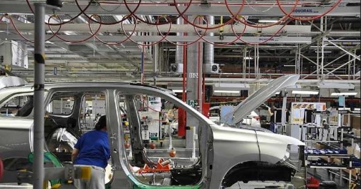
Homemade car the station wagon gives tremendous moral satisfaction. And the work done with your own hands, in my opinion, is the best rest from the main activity.
Vehicle layout Minimax
When creating "Minimax" (Fig. 1), I additionally solved the following tasks: transition to a completely closed body; expansion of internal dimensions without much increase in external, simplification.
Rice. I. The layout of the mini-car "Minimax" and suspension parts.
A - steering gear rocker:
I - rod of the gear rack SZA, 2 - intermediate link, 3 - threaded bushing of the rocking chair, 4 - rocking chair, 5 - ball ends, 6 - steering rods:
B - body preparation:
1 - door sliding back, 2 - frame. 3 - frontal panel, 4 - spare wheel, 5 - steering gear, b - steering post and instrument panel, 7 - windshield, 8 - opening part of the roof (aviasent), 9 - rigid part of the roof, 10 - glazing of the rear part of the cabin, 11 - body edging (dural square), 12 - side panel, 13 - SZA engine and main gear, 14 - longitudinal frame spar: 15 - the bottom of the passenger compartment, 16-door guide bar. 17 - door lock:
B - front suspension:
1 - trapezium paw. 2 - gusset plate for fastening the front axle SZA, 3 - reinforced bracket for fastening the lower shock absorber, 4 - upper cup, 5 - spring, 6 - lower cup, 7 - lower shock absorber ear, 8 - figured bolt, 9 - reinforcing tube.
Design features
The flat frame (Fig. 2) is made of steel welded pipes of rectangular section 50X25 mm, with a wall thickness of 2.5 mm, forming a rectangle 3200X1500 mm, with four transverse bridges and two additional longitudinal elements. The frame is essentially the main assembly slip: all other chassis and body assemblies are bolted to it.

Rice. 2. Frame structure made of rectangular tubes.
A - general view:
1 - longitudinal bars. 2 - crossbars. 3 - spar fastening the bridge:
B - section of the pipe.
In "Minimax" the doors are sliding. With a wagon body, this is easier to accomplish. In addition, this design allows them to be made much wider, without increasing the required parking dimensions, which is inevitable with swinging doors. And wide doors for a wagon-type minicar mean additional convenience for the driver and front passenger. In this sense, "Minimax" has certain advantages over, for example, a micro-car of the "Fiat" type, and a lightening of the power circuit; expansion of doorways; modernization of the steering mechanism.
Of course, along with its great advantages, the carriage layout has its drawbacks (otherwise, cars of this type would have already gained predominant distribution). First of all, it should be noted that the driver is not in the "comfort zone" near the center of gravity of the car. Therefore, it "pumps" much more than in cars of the classical scheme. If you do more soft suspension, this will lead to an increase in "galloping" - longitudinal rocking of the machine, generally characteristic of carriage layouts, which have a small base and spaced masses. This is especially noticeable when driving on rough terrain, in connection with which I had to slightly increase the stiffness of the front suspension.
The front position of the driver in a car of a wagon layout is also more dangerous in the event of a collision with an obstacle. Therefore, on "Minimax" the location of the spare wheel on the front panel of the body is accepted - it can, to a certain extent, work as a shock absorber. The key decision in order to improve safety was the choice of a frame: in the form of a body that goes beyond the dimensions of a closed load-bearing frame, located at a height of 400 mm from the roadbed.
Through the wide door they get into the Minimax and the passengers in the back seat; a refrigerator or other bulky luggage can be easily accommodated in the cabin. The dimensions of the hinged rear door also contribute to this.
The carriage layout imposes a limitation on the size of the wheels: after all, the driver's seat is located above the front axle. In addition, raising the center of gravity of the machine adversely affects its stability. In addition, it is necessary to fit into the existing technical requirements limiting the height: no more than 1450 mm.
The tires of 5,00-10 SZA fully satisfy all the conditions, although they limit the total weight of the machine to the permissible load: 250 kg per wheel.
The use of these tires prompted the use of motorized sidecar axles - the SZA suspension was taken as the basis for the front one, installed on two longitudinal welded box-section cross-beams, fixed on the first two transverse crosspieces of the frame. The required rigidity is achieved due to additional coil springs fitted to the shock absorbers. At the same time, the attachment point of the lower ear of the shock absorber is reinforced. The preloading of the springs is adjustable in the same way as it is recommended for the "Zaporozhtsev".
The layout of the engine compartment provides for the possibility of installing the power unit "Zaporozhets" ZAZ-965. However, the first version of the "Minimax" is equipped with an SZA power unit, with a slightly increased compression ratio (up to 7.8); at the same time, the rear part of the SZA frame with the engine, main gear and balancers is fully used rear suspension wheels.
I consider it my duty to warn followers that the use of the SZA (or SZD) undercarriage, even with the correct distribution of the load between the wheels, limits the running weight of the machine to the limit of 1000 kg. With a dry weight of "Minimax" of 640 kg, the payload, thus, does not exceed 300 kg. Therefore, on a long tourist trip, taking into account travel things, only 2 - 3 people can go in a car. The task of keeping within 640 kg is not an easy one, if in the process of creating the machine there is no strict control over the weight of the parts. After all, often built homemade products have a dry weight of about 800 kg (or even more), which leads to extremely rapid wear of rubber and suspension parts. For this reason, many homemade cars subsequently it is necessary to remake almost anew.
The steering, in addition to the units borrowed from the SZA, has a longitudinal rocker, the front end of which is connected by a rod to the steering rack. Ball joints of the steering linkage are fixed at the rear end of the rocker.
Drum brakes are installed on all four wheels. The hand brake only acts on the rear wheels.
The body is assembled from several separate units. The frontal part consists of two lower longitudinal rectangular pipes 50X25 mm, to which the posts are welded, and transverse steel profiles fastened to them with bolts, sheathed from below (floor of the front compartment) with getinax 7 mm thick, in front - with 4 mm textolite, behind and on the sides - sheet steel 1 mm.
The frame of the front glazing is welded from bent corners with a thickness of 1.5 mm and tubes 15X1.5 mm (upper contour and middle pillar). The windshield is made up of two halves cut from triplex.
The sides are assembled on M5 bolts from aluminum profiles and 3.5 mm getinax sheets. They are connected by the middle bulkhead (between the passenger and motorcycle compartments) and the tailgate. The sides and the middle bulkhead are attached to the frame, and the front edges of the sides are reinforced with struts made of the same rectangular pipes 50X25 mm. In the upper part, the edges of the sides in front and behind are interconnected by arcs welded from pipes 25X2.5 mm.
The longitudinal contours of the roof are formed by aluminum profiles with a rectangular section of 40X20 mm and a protruding shelf that serves as a drainage system and a guide for sliding doors. The profiles are fixed to the front glazing frame and to both arches.
The roof consists of two parts: the back one, between the arches - from sheet getinax; front - soft, on a tubular frame, removable.
The side glazing is assembled in frames of aluminum profiles. Rhombic doors run on two upper rollers, each with a lower guide. When closed, the doors fit tightly into the front groove of the frontal part and overlap with the trailing edge. Free sliding of the doors is provided by a special mechanism (see Fig. 1B). During the initial movement, the rear lower corner of the door slides in an oblique guide that takes the bottom of the door away from the body. The rear accessory door of the motorcycle compartment is suspended on two upper hinges.
The floor of the passenger compartment is made of 6 mm thick sheet of getinax and is fixed on the walls of 1 mm thick steel sheet between the middle cross members and the inner longitudinal frame elements.
The frames of the front seats are welded from steel tubes 20X1 mm, on which rubber strips from the Zaporozhets seats are stretched and leatherette covers are put on. Backseat and its back can be removed (when transporting cargo) or rearranged into the plane of the cover of the motorcycle compartment, as a result of which a common sleeping place of 1900X XI250 mm is formed. In this case, the front seats are not removed, and in the lower part of the cabin there is enough space for luggage.
The dashboard is placed on steering column... The gear controls are located next to the driver's seat. The rods and control cables run in the central tunnel below the frame level, and in the front and passenger compartments they are covered with covers.
The body is lined with plastic, imitating wood, outside and inside.

Rice. 3. Diagram of the mini-car "Minimax" in four projections and the main dimensions of the seats.
The shape of the machine was determined by the proportional composition of flat surfaces most typical for wood panels. At the same time, such planes are the most technologically advanced in relation to home production conditions. Insufficient aerodynamics of the adopted form practically does not play a role, since in urban conditions the average (and even maximum) speed is low. From the point of view of technical aesthetics, it should be noted that attempts to fit a panoramic Moskvich windshield into the body of the Minimax on several models (at a scale of 1:10) have shown that the car looks much better with flat glass. The design of the upper rails and the rhombic door contour also matches the selected body shape. As a result - with the length of the car less than that of the "Zaporozhets", its internal volume turned out to be larger than that of the "Volga".
As the experience of using a car in Moscow and on the roads of the Moscow region has shown (the mileage is over 30 thousand km), in general, the design of the car turned out to be successful. Winter operation has also convincingly demonstrated the great advantages of the air-cooled two-stroke engine.
Due to the high culture of weight, even with a 350 cm engine "a car with two passengers has sufficient throttle response for driving in the Moscow "green wave", and the maximum speed reaches 70 km / h. Low engine power is felt only on long climbs and when overtaking, or if two more passengers sit in the car: throttle response drops noticeably. Therefore, if distant tourist trips with the necessary luggage are expected, then it is advisable to install a more powerful engine.
P. Zak, Moscow
Toy cars Diskie Toys Cars 2 series copy the characters of the cartoon Cars 2 (Cars 2) and are popular with children. The author repaired a Mc Queen model car made in China, unknown release year. On the 3rd day, the car fell into the water, smoke came out of it, then it began to stop, not responding to commands from the remote control. There are no repair suggestions on the support website. In Moscow online stores, the warranty period for the exchange of faulty radio-controlled toys, at the time of this writing, was 7 days. According to the operating instructions, the RC (Radio-Car) Mc QUEEN is equipped with a certified 27138 radio control module with a frequency of 27 MHz. The author did not find any information on repairing this module. This article shows the electrical diagrams of the control panel (Fig. 1), the Mc QUEEN model cars (Fig. 2), describes the faults found and how to eliminate them (Fig. 3), note some features of the machine control.
On the diagrams, the alphanumeric designations of radio components correspond to the designations indicated on the circuit boards. The parts not marked on the boards were designated by the author himself. Parts marked on the boards, but not soldered, power dissipation of SMD resistors, jumpers, incl. SMD, not indicated on the diagrams. The marking of semiconductor SMD devices is indicated in the frame if it was applied legibly. All denominations shown in the diagrams have been read or measured. In the control panel, the contacts of the buttons SB2, SB3, SB4, SB5 are carbon, they are connected to the corresponding contact pads of the board with carbon tracks, the same carbon tracks are connected to the board with the middle pin SA1 and pin 10 ic2. These tracks are not marked on the board. They are marked on the control panel diagram with thick lines and a resistor symbol, indicating the resistance of a given carbon track, or a closed SB2-SB5 contact between two corresponding contact pads. Encoder of control commands of the console, IC2 chip marked "515T", and decoder of machine control commands, U2 chip marked "515R", in SOP 14 cases, made in China. It is not known whether they are programmable, but they have a memory capacity for one or two commands; the author did not find a description of these microcircuits.

The control panel consumes a current of 50-150 mA. Its performance is maintained when powered by 3 LR6 batteries up to 3.3V. LEDs D19-D20 are indicators of switching on the remote control. From pin 8 of ice2, the radio transmitter of the control panel is switched on, and codes are transmitted that modulate the emitted signal. From pin 9 of ic2, the control signals are fed to pin 3 of ic1 of the sound processor, a "black pill" located on a separate board, 8 by 15 mm.

Sound effects are recorded in ic1 memory in 2 second files. When a control signal arrives, ic1 selects the desired file and broadcasts it continuously until the end of the control signal. The SPK speaker is located inside the control panel. The first two days, the remote control could say the phrase: "Talk to me."

Scheme 1

Scheme 2
Forward and backward movement is carried out by the electric motor of the M1 machine, its operation is controlled from the remote control by a variable resistance RW1, included as a rheostat. The proportional control scale LEDs turn on sequentially, starting from D18-D17 to D11-D10, they indicate the deviation of the RW1 slider from the middle position when moving forward and backward. The movement speed is controlled by changing the frequency of the forward - backward commands from the control panel. But this adjustment is not very effective, because at low speeds, the electric motor does not have enough torque and the machine begins to twitch at the start. Turning left and right is performed by the electric motor of the M2 machine, and is controlled from the remote control by the SA1 switch. To execute the “Reverse” command (Circular rotation), pressing the SB1 “MODE” switch from the remote control turns on the electric motor of the M3 machine and the spring-loaded platform with the reversal wheel fixed to it is lowered from the upper position. In the lower position of the platform, the turning wheel extends and abuts against the floor surface, the gear on its axis engages with the gear of the gearbox of the drive wheel motor M1, at the same time the rear drive wheels are torn off the surface, the SF3 contact is opened and SF2 closes, after which the M3 engine stops. Now the commands coming from RW1 and SA1 are blocked, and the M1 motor will be controlled by the position sensors SQ1 and SQ2 and rotate the reversal wheel. Contacts SQ1 and SQ2 should be triggered when the remote control is wiggled from side to side, when one of them is closed, the machine turns to the right or left for 3 seconds, then stops on its own. Sensors SQ1 and SQ2 are metal, cylindrical, with axial leads, without marking. Inside, judging by the sound, there is a ball. When the sensor is turned with the golden lead down, the contact inside the sensor is closed, and when it is turned down, the silver lead is opened. The sensors are located on the rear wall of the control panel at an angle of 90 degrees. one to the other, but the angle of their operation is more than 150 degrees. Perhaps this is why one of them was installed upside down in the remote control, and in order to change the direction of rotation of the machine, the remote control had to be turned up and down with the antenna. To cancel the command for circular rotation, turn off SB1, after which the engine M3 is turned on again: the platform of the reversal wheel rises, the gear on its axis is disconnected from the gearbox M1, SF2 is opened, the drive wheels are lowered to the surface, in the upper position of the platform, SF3 is closed and M3 stops.

Scheme 3
The car consumes more than 1A current while driving. When powered by 8 LR6 batteries, it remains operational up to a voltage of 10.5V (1.3V per cell). Semi-discharged cells of this standard size do not "hold" a large current for them, so the use of batteries is undesirable. The self-resetting fuse FU1 has no marking and has never tripped. The U1 microcircuit without marking is probably a dual operational amplifier, similar to the one included in the Chinese PTBA978B microcircuit, the "trim" of their terminals is the same, the ratings C4, C6, C9, C13 are taken from. Outside the machine's receiver board, there are M1, M2, M3 electric motors, SF1-SF3 sensors, a power connector and switch, headlight LEDs, a board with R14-R17 resistances. M1 and M3 engines with gearboxes, a platform with a turn wheel, driving wheels are assembled into a single block of the rear axle. The SF1 sensor is located in a non-separable assembly for the reversal wheel axle, there is no access to it, its contacts close and open at each rotation of the reversal wheel. Sensors SF2 and SF3 are push-action micro-switches, SF2 is mounted at the very bottom of the block, it is most susceptible to contamination. The SF3 sensor is located at the top of the assembly. All three sensors are connected by wires to the corresponding contact pads on the board: K2, K3, K4, when triggered, they close the corresponding terminals of the U2 microcircuit to the common wire. If the contacts of the SF2 and SF3 sensors are broken, or their connecting wires are broken, after giving or canceling the "MODE" command, the M3 engine continues to work, continuously lowering and raising the reversal wheel. The U2 decoder, having noticed an error in the execution of the command, locks itself and stops the execution of all commands. To restart U2, the machine must be turned off and then turned on again with the SA1 switch.

The broken machine turned off after pressing the SB1 button on the remote control due to the impossibility of executing the "MODE" command. On its board, before charring, the transistors Q8 and Q11, which control the M3 motor, burned out, so that it was impossible to establish their type and conductivity. A complementary pair of transistors connected by emitters to the "+" of M3 would turn it on with the closed transistor Q7. But M3 must be turned on by the "MODE" command when Q7 is opened, then the p-n-p transistor Q11 and the n-p-n Q8 must be connected by collectors to the "+" pin of M3. After installing in place Q8 and Q11 a pair of transistors "8050" and "8550" collectors to "+" M3, it started working, but during the day these transistors burned out again. I had to draw diagrams and figure out the reason for what happened: it turned out that when Q7 was switched, a through current flows through the transistors Q8 and Q11 for some time, and, like on the board, connecting their base terminals to D9 only increases this current. When the "MODE" command is executed, the M3 turns on for only 2-3 seconds, so this scheme could work for several days. But if the MODE command is turned on frequently, or if the resistance of the SF2-SF3 contacts increases, the transistors Q8 and Q11 would necessarily burn out. To avoid the through current, the n-p-n transistor Q8 was removed from the M3 control circuit, it would be removed immediately and nothing would have burned out. In place of Q11, 2Т836Б was soldered, everything worked, but due to the peeling of the foil of the contact pads Q11, (earlier it burned out stronger than Q8), it was necessary to change the M3 switching circuit. The result of the repair is shown in Fig. 3. Removed from the board: diode D9, peeled foil of contact pads Q11. In place of D9, R28 is installed, the 2T836B transistor is soldered into the holes of Q8, the place of Q11 is left free. The “+” M3 pin is connected to the plus of the board power supply, and the “-” M3 pin is connected to the 2T836B emitter.

It is possible that the receiver board was intended for another product, and was subsequently adapted to this model of the machine. It is possible that only part of the machines of this series got the defective board.
Due to the increase in the resistance of the contacts of the SF2 and SF3 micro-switches, they were washed, for which the rear axle of the machine had to be disassembled. In the control panel, the SQ1 and SQ2 sensors have been replaced by pushbutton switches installed on the back of the control panel. Machine control has become more convenient. The plastic tube, designed to support the antenna wire of the machine in an upright position, broke, and we had to install a removable antenna on the machine.
After repairs and alterations, the machine has been working without breakdowns for many months.

Bibliography:
1. Website http://service.dickietoys.de
2. Internet site http://www.masteraero.ru "How to remake and install radio control equipment from Chinese toys ..." Author V. Saveliev
3. Internet site http: // supreg 1. narod.ru "Receiver for radio-controlled toys" Author Martemyanov A.
This article is a modeller's story about making a homemade radio-controlled model of an all-wheel drive car. Range rover from a plastic model. It reveals the nuances of manufacturing axle drives, installing electronics and many other nuances.
So, I decided to make a car model with my own hands!
Bought a regular Range Rovera bench model from the store. The price of this model is 1500 rubles, in general it is a little expensive, but the model is worth it! Initially I thought of making a hummer, but this model is much more suitable in design.  I had electronics, well, I took some spare parts from a trophy collector called "cat" which I didn't need for a long time and was disassembled for parts!
Of course, it was possible to take other prefabricated models as a basis, but I wanted just such an off-road jeep.
It all started with bridges and differentials that I made from copper pipes and soldered with an ordinary 100w soldering iron. Differentials are ordinary here, the gear is plastic, the rods and the drive bones are made of iron from the trophy. 
These tubes can be purchased at any hardware store. 
I took the differential gear from a conventional printer. I didn't need him for a long time, and so I decided that it was time for him to retire.  Everything turned out quite reliably, but it is rather inconvenient to work with a soldering iron!

After I made the differentials, I had to close them with something, I closed them with caps from under the pills.  And painted it with ordinary auto enamel. It turned out beautifully, although the trophy drinker hardly needs beauty.
Then it was necessary to make steering rods and put the bridges on the frame, the frame was included and to my surprise it turned out to be iron, not plastic.


It was quite difficult to do this, since the scale of the parts is very small and it was not possible to solder here, I had to screw it with bolts. I took the steering rods from the same old trophy case that I disassembled.

All the parts of the differentials are on bearings. As I have been making the model for a long time.  I also ordered a gearbox with a reduction gear, the gear will be turned on by a microservice from the remote control.

Well, in general, then I installed a plastic bottom, cut out a hole in it, installed a gearbox, cardan shafts, a homemade gearbox, an ordinary collector engine for such a small model, there is no point in setting the bk, and the speed is not important to me. 
The engine is from a helicopter, but in the gearbox it is quite powerful.
 The most important thing is that the model does not go in jerks, but smoothly without delay, the gearbox was not easy to make, but the main thing is ingenuity.
The gearbox was screwed to the bottom, it held up perfectly, but to attach the bottom to the frame I had to tinker.

 Then I installed electronics, shock absorbers, and a battery. At first I put the electronics rather weak and the regulator and the receiver were a single whole, but then I put everything separately and the electronics were more powerful.

.1390645053061.prev.jpg)


And finally, painting, installing all the main units, decals, headlights and more. I painted everything with usual paint for plastic in 4 layers, then painted the wings brown and sanded the parts to give a worn and worn look. 
 The body of the model and the color are completely original, the color was found on the Internet and photos real car I did everything according to the original. This combination of colors exists on a real machine and was painted in this color at the factory.

Well, here are the final photos. I will add a video with the test a little later, and the model turned out to be very passable, the speed was 18 km / h, but I did not make it for speed. In general, I am satisfied with my work, and you will appreciate it.
 The machine is not large, scale 1k24 in size and there is the whole point of the idea, I wanted myself a mini trophy.


The model is not afraid of moisture! He sealed everything himself, he simply covered the electronics with varnish, very reliably, no moisture is terrible.
 Servomachine micro park from the plane to 3.5 kg.


The battery is enough for 25 minutes of riding, but I will put more powerful electronics and a battery, because this is not quite enough.


Even the bumpers are the same as on the original. And the mounts on them are the same. The drive on it is not 50 to 50%, but 60 to 40%.

In general, the Range Rover turned out in a rustic style, I did not even think that it would turn out to paint so high-quality because I don't really know how to paint, although there is nothing difficult! .1390645295252.prev.jpg)

I forgot to add for beauty, I also installed a roll cage and a full-fledged spare tire. The spare wheel and frame were included with the kit.

More about radio-controlled models:
Mishania comments:
Tell me how it works four-wheel drive, inside the bridge, what is there for the hand-outs? There should be rounded fist after all.
I built the first micro-car "Mouse" for my children. How successful it was, the readers of "Modelist-Constructor" can judge by reading its description and drawings published in "".
As a result, I gained some experience in designing and conceived not a child's, but an "adult" car - for myself. He called her "Mouse-2". It took a long time to build, or rather, not so much building as looking for the necessary parts, units. This, in particular, explains the use of mechanical brakes in "Mouse-2" (now I am changing them to hydraulic ones). The development of the drawings and the construction were carried out simultaneously, although the main parameters of the "Mouse-2" were thought out by me in advance.
I will give him a short technical characteristics... It is a two-seater four-wheeled vehicle with a 14 hp engine. with. (working volume 346 cm 3), located at the back. Equipped with two independent brake systems: main (working) with pedal drive to all wheels and spare (parking) with lever drive only to the rear wheels.
The car is dynamic and stable. The braking distance at a speed of 30 km / h is not more than 6.5 m. The smallest turning radius along the axis of the track of the outer wheel is 4.5 m. Maximum speed 65 km / h.
Electrical equipment - from the S3D motorized carriage, 12-volt, slightly modified. It includes external lighting and light signaling devices, a sound signal, a wiper, and instrumentation.
The salon is finished with modern materials, isolated from the motor compartment with a sound-absorbing panel with foam filling. The driver's and passenger's seats are anatomical, glued from fiberglass, lined with foam rubber and sheathed with leatherette; the car is equipped with seat belts.

The car has been in operation since May 1985. There are already many thousands of kilometers of Sakhalin roads on the speedometer. There were no serious breakdowns on the way. True, I should note that at full load, the engine power is not enough to overcome the steep and long slopes that are often found on our roads. And this forces you to include the first gear. I am also critical of the doors that can be folded up - not in all they are comfortable. The rest of the car is happy.
Now I would like to tell you about the design features of "Mouse-2".

1 - front buffers,
2 - sidelights - direction indicators,
3 - retractable headlights with covers,
4 - battery,
5 - front axle,
6 - steering shaft,
7 - luggage compartment,
8 - brake and clutch pedals,
9 - gas pedal,
10 - hand brake handle,
11 - gear and reverse lever,
12 - driver's seat,
13 - headlight lift,
14 - "coins" of the decompressor and corrector,
15 - valve of the fuel cock,
16 - differential with reverse gear,
17 - drive chain,
18 - engine,
19 - fuel tank,
20 - mufflers,
21 - back buffer,
22 - taillights.
It is assembled mainly from spare parts "Zaporozhets" and motorized sidecars SZA and SZD. The body is frame, with fiberglass panels on a tubular basis. The rear hood is hinged or removable for easy access to the engine. The body is the most labor-intensive part; it takes three quarters of the time to assemble and equip it.
First, I made a life size mockup of the body. I used pure plaster of paris. To save money, he first laid concrete on the mesh, and when it set, he applied a layer of gypsum 15-20 cm thick on top. The completely dried surface of the model was sanded and painted with nitro enamel. The processing was carried out very carefully so that the flaws do not pass to the matrix.
Then he marked out the lines of parting of the panels. So that they are clearly imprinted on the matrices, I drew them with an awl to a depth of about 1 mm. Finished panels were fitted along them.
Usually matrices are made of fiberglass. But I needed to save resin and fiberglass, and I had to cast them, like the model, from plaster and concrete.

Rice.3. Typical panel joining scheme:
1 - skeleton tube,
2 - wooden lath-insert with a groove,
3 - fiberglass linings,
4 - sealing the joint of panels with fiberglass,
5 - panel,
I took off the blindfolds of each panel separately: rubbed the surface of the model with a thin layer of petroleum jelly or solid oil and washed it down with plaster, overlapping the parting lines by 10-11 mm, and then with concrete, reinforcing it with steel bars Ø 5 mm. To obtain casts from vertical surfaces, he made formwork from boards and plywood.
After the concrete had dried (after about three days), he removed the matrices, dried the plaster layer, carefully processed and painted.
The main load-bearing panels were glued from six layers of fiberglass lined with two layers of fiberglass, which gave a thickness of about 4 mm. Before this, the fiberglass was burned with the flame of a soldering pump so that it better absorbed the resin. He fired it with great care, since the tissue crumbles in places of the burnout.

Due to the fact that the glue thickens quickly, I had to cook it in small portions, Composition: epoxy resin (100 cm3), plasticizer (10 cm3) and hardener (10 cm3). You can do without a plasticizer. If the resin is too thick, it is allowed to add acetone or solvents no. 646 or no. 648 (no more than 10% of the total volume). However, given that such additives somewhat reduce the strength of the product, they should be used as a last resort.
To obtain the desired color scheme, a dye is introduced into the resin - ordinary artistic oil paint from a tube (before adding the hardener).

Fig. 5. The main power elements of the body:
1 - front buffers,
2 - front axle (steering gear and suspension arms are not shown),
3 - car frame,
4 - luggage compartment edging,
5 - front supports of the body frame,
6 - frame pipes,
7 - lower supports of the frame,
8 - door bar,
9 - door frame,
10 - door hinges,
11 - back supports of the frame,
12 - hood frame,
13 - bonnet hinges,
14 - back buffer.
Before gluing the panels, I cut the fiberglass in layers with a knife on a sheet of plywood (linoleum) and stacked the pieces in a pile. Glued in one go with short breaks for rest or dilution of a new portion.
After laying the last layer of fiberglass in the matrix, he covered everything with plastic wrap and, having made the formwork, covered the surface with sand. A day later, he removed the sand press and left the panel “to ripen” in the matrix for three more days. The resin is completely polymerized in a week.
Opening for windshield in the front panel, I adjusted it to a frame made of a two-millimeter aluminum sheet, Then this frame is glued into the panel and a frontal triplex from a ZAZ-968 car is inserted into it. The rear glazed panel was manufactured in the same way.

1 - engine,
2 - an adjusting screw,
3 - adapter,
4 - front engine mounting bracket,
5 - sub-engine frame,
6 - differential suspension rods,
7 - differential with reverse gear,
8 - protective pallet,
9 - rear bracket engine mounts,
10 - muffler hinge plate,
11 - left muffler.
I cut the finished panels along the parting lines on the body mockup and fitted them to the tubular frame. He fastened the panels to it with screws, choosing the gaps with wooden slats with grooves and gluing them from the inside with 4-6 layers of fiberglass. He cut the joints between the panels with steps and filled them with strips of fiberglass on glue.
The assembled body was finally putty and sanded, preparing for painting. The irregularities were repaired with a putty based on the same epoxy glue, adding fillers to it: talcum powder, aluminum powder, and the like.

1 - front supports,
2 - lower supports,
3 - rear supports,
4 - supporting pipes.
The body frame is assembled from thin-walled steel pipes, to which the attachment points to the car frame are welded: front, lower and rear supports.
The frame of the folding hood also has a tubular structure. If necessary, the latter can be removed altogether, for example, when repairing an engine.
The main power element of the body is a rigid frame made of steel pipes and corners. It carries the frame, hood, front axle, engine with sub-frame and differential, rear wheel suspension, trunk and so on. Brackets, assemblies and supports are provided for fixing these units.

1 - brackets for attaching the front axle,
2 - brackets for fastening the gear lever and reverse,
3 - support of the passenger seat,
4 - lateral joints of the body frame,
5 - loops for attaching the passenger seat,
6 - support for the pillows of the sub-engine frame,
7 - towing fork,
8 - bonnet pins,
9 - corners 40 X 40 mm,
10 - attachment points for the rear wheel suspension.
In front, on the frame, there is a bridge from the SZA motorized carriage, modified for shoe brakes from a cargo motor scooter.
On the rear of the frame, on self-made rubber cushions, a sub-engine frame is mounted with a power plant from the SZD motorized carriage, deployed 180 °. The front fork of its fastening is an adapter, offset vertically relative to the engine mounting bracket. Rear point - articulated: the bracket, covering the pipe of the sub-frame with a clamp, allows a slight rotation power plant in the vertical plane. This is done to tighten the drive chain with an adjusting screw, which, pushing away from the support area of the front bracket, raises the engine. The chain tension is secured with a clamp and tie rods (see Fig. 9 and Fig. 10).

2 - longitudinal spars,
3 - transverse spars,
4 - protective pallet,
5, 6 - differential suspension rods,
7 - cheeks of the rear engine mounting bracket,
8 - tie rods,
9 - holes for differential suspension studs,
10 - stiffeners,
11 - pipe for the rear bracket clamp,
12 - clamp.
The torque is transmitted by a single-row roller target with a pitch of 15.875 mm to a differential with a reverse gear from a cargo scooter. The differential is suspended on four pins under the engine on the sub-frame rods. In principle, it is not much different from a sidecar - just as compact and reliable. However, in order to obtain the required number of wheel revolutions, a new sprocket with 16 teeth had to be made for it.
The gearbox, as you know, is built directly into the engine, and the reverse is integrated into the differential. To control them, you must have two levers with separate drive. I used a single drive for shifting both gears and reverse, which greatly simplified driving.

Rice. 10. Installing the adapter:
1 - front engine mounting bracket,
2 - adapter,
3 - an adjusting screw,
4 - adjusting hole,
5 - tie rod.
The shift lever in the cab is hinged between the two sectors of gear and reverse and is constantly pressed against the first by a spring. In the neutral position, the sectors are fixed by balls, which, under the action of their springs, enter the grooves of the discs.
For reverse the gear sectors are shifted forward with the lever - turn on the first gear. Then the lever is returned to the neutral position (the transmission is not turned off) and again, but already with the reverse sector, is fed forward, including reverse.

3 - sector of gear shifting with a disk,
4 - reverse sector,
5 - pressure plate,
7 - corner of the car frame,
8 - reverse thrust fork,
9 - a fork of a rod of a gear change,
10 - arm mounting bracket,
11 - plug,
12 - retainer spring,
13 - retainer ball,
14 - gear shift thrust.
The rest of the engine controls - the gas pedals, the clutch and the ignition switch - are standard.
The layout of the power plant in the engine compartment dictated the replacement of one factory muffler with two self-made ones - the first did not fit into the engine compartment.

1 - power transmission,
2 - car frame,
3 - suspension arm,
4 - suspension supports,
5 - pad,
6 - wheel hub,
7 - suspension arm fastening eyes,
8 - bushings,
9 - rubber pads,
10 - finger
11 - housing of the lower shock absorber mounting unit,
12 - rib,
13 - lugs of the upper shock absorber mounting unit,
14 - kerchief.
Silencers are welded from sheet steel. Connected them to the cylinder exhaust pipes (union nuts) and to the engine mounting bracket
(by mounting plates]. It should be noted that the exhaust sound at homemade mufflers louder than the factory one. Probably, this is due to their small internal volume. However, this does not affect engine power.

1 - tie bolt,
3 - muffler casing,
4 - supply pipe,
5 - union nut,
6 - plate for mounting on the rear engine mounting bracket,
7 - ejector,
8 - perforated pipe,
9 - bottom,
10 - exhaust pipe.
Rear axle assembled from two self-made independent suspensions with longitudinal swing of levers. I installed the levers from thick-walled steel pipes Ø 32 mm with supports in the ears - the attachment points to the car frame.
To the opposite ends of the levers, I welded the rear wheel hubs and the lower shock absorbers, which are cylindrical bodies with bushings for axle bolts and rubber bushings.

1 - shock absorber of the Ural motorcycle,
2 - plates for an additional spring,
3 - rubber buffer,
4 - shock absorber spring,
5 - additional spring,
6 - biscuit.
The upper attachment points of the shock absorbers are the lugs on the gussets welded to the tubular elements of the car frame.
Rear wheel hubs and axles - from a cargo scooter; rims and brake parts - from the SZD motorized carriage. They are connected into a single whole by flanges and discs.

1 - semi-axle with cardan joint,
2 - hub axis,
3 - hub housing,
4 - roller bearing,
5 - brake shield flange,
6 - a disc of a wheel and a brake drum,
7 - segment key,
8 - disc fastening nut,
9 - inner rim,
10 - brake drum,
11 - outer rim,
12 - brake shoe,
13 - brake shield.
The rear axle of the Mouse-2 is heavily loaded, and the elasticity of the shock absorbers from the Ural motorcycle, as it turned out, is not enough. Therefore, they had to be finalized - to install additional springs, which I made from one spring of the rear suspension of a ZAZ-968 car, cutting it with a gas burner. The edges of the cuts were folded over while hot and then grinded in emery for a precise fit into the plates.

1 - roller bearing,
2 - stuffing box,
3 - steering knuckle,
4- additional flange,
5 - a bolt of fastening of a brake shield,
6 - hub,
7 - brake shield,
8 - brake shoe,
9 - brake drum,
10 - coupling bolt,
11, 12 - wheel rims,
13 - spacer ring.
The shock absorbers have not undergone a more complex alteration. I only removed the outer covers. And to prevent dirt from getting on the rods, I used protective covers made of thin canvas.

Rice. 17. The layout of the retractable headlights drive:
1 - bearing,
2 - the axis of the body,
3 - headlight housing,
4 - screw for fastening the shelf,
5 - speedometer cable,
6 - drive handle,
9 - shaft bearing housing,
10 - spacer sleeve with shaft,
11 - gearbox housing,
12 - headlight mounting panel,
Fig. 18. Headlight drive mechanism:
1 - handle,
2 - flywheel,
3 - the body of the turntable,
4 - speedometer cable,
5 - cable sheath,
6 - worm shaft,
7 - worm wheel,
8 - gearbox housing,
9 - lever lock,
10 - lever,
11 - shaft bearing housing,
13 - spacer sleeve.
Power axle shafts with cardan joints- also from a cargo scooter. But since the track "Mouse" is wider, they had to be lengthened. I cut the axle shafts in half and pressed them into a steel bushing. Having adjusted their length in place, welded to each other.
The front wheel suspensions are assembled from the chassis parts of the SZA and SZD sidecars. To connect them together, I carved additional flanges and attachment rings. The details of the chassis (except for the hubs) have not been finalized. And the hubs were only grinded in three places, as shown in the figure.


I still have the headlights with a manual drive (over time it will be replaced with an electric one) installed in the cab. From turntable to worm gear with a gear ratio of 1: 80, the speedometer cable is pulled in the sheath. Further, from the worm wheel of the gearbox, rotation by the shaft hidden in the spacer sleeve is transmitted through the levers and rods to the headlight housings, and they are extended. They are adjusted by shifting the shelves, which are then fixed with side fastening screws.
Not only children are now interested in toys. Many adults buy exact copies of cars famous brands or they are looking for radio-controlled models of cars. Among the offered assortment of toy stores, it is not always possible to find an option that will completely suit the client. In some cases, it is much better to make a radio-controlled model of a car yourself, your child will appreciate your efforts. A do-it-yourself gift from improvised means is much more valuable than a bright typewriter bought at an expensive toy store.
You can make your own radio-controlled car using our sequential algorithm. Modeling from one finished model of a car to another is very similar to the actions of craftsmen in a car workshop.
To create a do-it-yourself controlled machine, you need to have the following elements:
- Electric motor;
- Frame small car;
- Robust chassis;
- Removable wheels;
- Mini screwdriver set;
- Detailed instructions for accessories.
Undoubtedly, self-assembly of the machine on the remote control has a lot of advantageous advantages, namely:
- Saving money, while you will have the model of the car that you wanted;
- You can choose the model you need from the offered assortment of spare parts and body types;
- You decide - to make a mini-typewriter on a wired remote control, or use a radio control, which will have to spend a large amount.
After you decide on the model, follow the following sequence of actions:
- We select a chassis for your model, pay attention to the quality of all small parts. No blotches and notches on the surface of the plastic should be visible, the front wheels should move smoothly;
- When choosing wheels, pay special attention to models with rubber, since all plastic models have a poor quality grip surface;
- Take the choice of motor with all seriousness, since this is the main heart of the mini-car. There are 2 types of mini-motors for cars - electric and gasoline. Electric motors are affordable and easy to use, they are powered by a battery, and it is very easy to recharge it. Gasoline options have more power, but they are more expensive and require delicate care. They need to be injected with special fuel. For beginners in the field of toy car modeling, electric motors are suitable;
- You need to decide on the type of control - wired or wireless. Wired controls are cheaper, but the car will only move within a limited radius, while the RC model will move within antenna range. The radio unit is much more efficient for mini-cars;
- The body of the future car also deserves increased attention. You can choose a ready-made case or make it according to your personal sketch.
After all the parts are purchased, you can start assembling.

We attach a motor and a radio unit to the chassis. We mount the antenna. Together with the accessory parts must go detailed instructions on the assembly of the entire machine. We are adjusting the work of the motor. After everything is working properly, fix the sturdy body of the mini-car to the chassis. Now you can decorate the created model as you like. Let's make a car with a powerful motor.
Many will find the idea of assembling a motorized car for their child very strange, since there are many ready-made options on store shelves. But if you strive to show individuality and earn credibility in the eyes of your child, then you can start assembling a machine with a motor, although it is not easy to do, but the result will justify all the efforts.

The best option is to start assembling a radio-controlled model. This will require certain skills and knowledge of small electrical engineering, because this mini-machine is a rather complex mechanism, despite its compact size. All important parts must be purchased.
We begin to study the control panel. The movement of the car, the ability to overcome obstacles, and make beautiful maneuvers directly depends on the correct assembly. Many car models use a three-channel pistol-style remote control, which you can assemble yourself.
You can follow a simple path - get a special designer, where the kit contains all the necessary parts, their detailed diagrams and final drawings of the finished models.
The motors for future RC models can be electric or internal combustion... Internal combustion engines produce gasoline or incandescent, operating on a composition of methanol, oil and nitromethane, a special gas-alcohol mixture. The approximate volumes of such engines range from 15 to 35 cm3.
Approximate volume fuel tank for such machines is 700 cm3. It provides the engine smooth operation within 45 minutes. Many gasoline models have rear drive, an independent suspension is mounted on them.
Today, there are many demountable models on the market for car builders. Among the leading manufacturers of mini-cars, it is worth highlighting ABC, Protech, FG Modelsport (Germany), HPI, HIMOTO (USA). Their main feature is the similarity of mini-models with real prototypes. After completing the assembly, according to the attached instructions, install a charged on-board battery, a battery in the transmitter, pour a small amount of gasoline into the tank. You can safely launch your iron horse let's hit the road.

Modeling cars of your own accord is a fun hobby, especially when the result exceeds all expectations. To begin with, you need to purchase a Range Rover bench model, from which we will make a jeep that can freely dissect off-road. We also need to take working electronics from an old jeep, we will fix it in an SUV.
We make bridges and differentials from copper pipes with a soldering iron. We attach it to the powerful wheels of the SUV. Care must be taken to ensure that all connections are firmly sealed. We closed the sharpening differentials with pill caps. From above we cover the entire joint of the differential with ordinary auto enamel. We put the bridges on the frame and carry out the steering rods. Steering rods can be obtained from an old disassembled machine. After installing the plastic bottom, we cut out a hole there, which is necessary for installing the gearbox, cardan shafts. The gearbox contains an airplane engine, which is also quite powerful. The model does not move in jerks, but smoothly, this is the most important condition for such models. It is quite difficult to make a gearbox, but here you can show all your ingenuity. We fix the gearbox tightly to the bottom, attach the bottom to the frame. Now the electronics, shock absorbers, battery are being installed. At the end, the car body is painted, the main units are installed, the headlights and much more. We apply the paint in 4 layers for ordinary plastic. The author found the original photo of the car and made a mini-copy of it in a toy version. So that the model is not afraid of moisture, he covered the electronics with a special compound. To give the effect of antiquity, I sanded the outer surface of the car after painting. The battery in this model is enough for 25 minutes of continuous riding.

To create such a simple model, we need the following list of small details:
- Microcircuit for a radio-controlled car;
- Remote Control;
- Steering element;
- Soldering iron with solder;
- Compact electrical device;
- Battery with charger.
The procedure is as follows:
- We collect the lower part of the car, that is, the suspension;
- For this purpose, a strong plastic plate is required, it will be the basis for this model;
- A microcircuit for a radio-controlled car is attached to it, we solder a wire to it, which serves as an antenna;
- We solder the wires from the electric motor;
- We fix the battery wires to the correct points of the microcircuit;
- We fix the wheels taken from a simple children's car;
- All parts can be secured so as not to fall off during use.
We fix the steering elements, it is impossible to do this with glue alone. The front axle must be wrapped with electrical tape for a stronger fix. We attach the battery to a microcircuit. The machine is now ready for testing. It must definitely function. The control of such a machine is carried out using the remote control. By following these instructions, you can easily make a new typewriter on the control. If you want to design with your own hands, then this guide is more useful than ever. A handmade toy pleases much more than a model bought with your own hands.

To assemble this model, we need the following components:
- A simple model of a car of any production;
- VAZ parts for opening doors, 12-volt battery;
- Radio control equipment;
- Durable batteries with chargers;
- Radiator;
- Electronic measuring equipment;
- Small soldering iron with solder;
- Locksmith tools;
- A piece of rubber to provide reinforcement for the bumper.
An approximate scheme for collecting a radio-controlled model is shown in the figure.

Let's move on to reading and collecting the diagram, to the fascinating process of creating a unique mini-typewriter. First, we collect the suspension. We take VAZ connections and gears for assembling the gearbox. The studs and housing need to be threaded in order to hang the gears and solenoids. We connect the gearbox to the power supply, check it, and then fix it on a typewriter. To effectively protect the system from overheating, we install a radiator. The plate from it can be firmly fixed with ordinary bolts. Next comes the installation of power driver and radio control microcircuits. We completely install the car body. Our mini car is ready for real challenges.

You have a radio-controlled car. Are you looking to make it more agile, but don't know how to do it?
Do not overload the model with additional systems and unnecessary small details. Sound signals, glowing headlights - these are all conveniences, they look great, but the independent process of collecting a radio-controlled car has certain difficulties even without it. Complicating details can negatively affect important undercarriage auto. The main point to focus on is the creation of a high-quality suspension, ensuring reliable signal transmission.
For improved agility and optimization speed parameters fine-tuning the system during test drives will do. These guidelines will help you to understand the business of car modeling. You can create a typewriter yourself, which will be a real copy of a large model. All the details will be similar, only your version will have everything in a mini-format.

Make your son happy - make a car with him on the control panel
You can start with a simple one - to assemble a construction machine on the remote control. First you need to come up with a project: how your car will look like, how it will move, view other details. To start immediate assembly, you need to prepare not only all the important components of the future iron horse, but also the necessary devices. To start an exciting joint activity with our sons, we take the following things:
- Small motor, can be borrowed from an old vein or a household fan;
- Sturdy frame;
- Mini rubber kit;
- Quality suspension for a small chassis;
- 2 sturdy axles for fixing the wheels;
- Wireless antenna;
- Thin wires for connections;
- High-quality batteries for the accumulator or special gasoline;
- Assembled signal receiver;
- An old remote control, a simple transmitter or an outdated radio unit will do.
From the devices you will need pliers, a small soldering iron, screwdrivers of various diameters.
Assembly order
During the collection process, it may turn out that some of the missing parts will have to be bought or borrowed from the old, broken machines of the little son. After all, he will sacrifice them for the sake of a cool novelty, isn't that so ?! We take the frame and body from the old samples of the son's toys. The selected motor is tested in advance for maneuverability and performance. The power of the engine should not go against the weight of the car, because weak motor will not pull heavy construction. Batteries must be unused. The step-by-step assembly steps are as follows:
- First, we assemble the mini-frame;
- Then we fix and adjust the serviceable motor;
- We introduce batteries or a compact battery;
- Next, the antenna is fixed;
- The wheels are mounted so that they can turn freely, spinning with the axle. If this condition is not met, the machine will only move forward and backward.
For the future iron horse, it is better to take rubber tires, since they perform best on open ground. If the assembly process was easy enough, you were able to figure out all the intricacies of the primary car modeling, then you can make several samples, you can give another copy to a neighbor's boy. They will arrange outdoor racing on the street.
Assembling a new unique car is a fascinating process for which dad and son can spend more than one evening. To turn it into a productive business, you can follow the following recommendations, they must be taken into account when assembling a modern toy:
- Sketch future model that you want to collect or use the ready-made collection instructions;
- Purchase everything quality details cars;
- Additional parts can be taken from old machines or purchased new ones;
- Before installation, thoroughly test the selected motor, this is the heart of the machine;
- Don't skimp on batteries for a new model, keep them new and unused;
- Firmly fix all the details, according to their sequence;
- Study the schemes for creating similar cars in advance to facilitate the assembly process;
- Choose a ready-made model or come up with something of your own, unique.
Following these recommendations, you and your child will easily make the chosen model of the machine. You can make and collect exact replicas of the original cars when you reach a certain skill level. Putting together a car in a family circle - that's the best way effective organization of leisure for yourself and your child.
A self-assembled machine will be a valuable present for your children, because real fatherly feelings are embedded in it. When assembled, the model will travel in the selected direction and is easy to maneuver. You can learn how to make a simple version of the typewriter by following the recommendations from the proposed video. Start your journey in the world of car modeling!