Differential KamAZ. Device and principle of operation
1. MAIN GEAR AND DRIVING AXLE DIFFERENTIAL
1.1. The purpose of the drive axle mechanisms
Each drive axle is equipped with a main gear and an inter-wheel differential. In addition, a center differential is installed on the middle drive axle of the KamAZ-5320 car.
The main gear of the car is designed to constantly increase the torque supplied from the engine and transmit it at right angles to the drive wheels.
The constant increase in torque is characterized by the final drive ratio.
On KamAZ vehicles, depending on the destination ratio the main gear is 5.43; 5.94; 6.53; 7.22. On the Ural-4320 car, it is 7.32. On modifications of vehicles intended for use as truck tractors, the gear ratios of the final drive are increased.
On the KamAZ-5320, double main gears are used, consisting of two gear pairs, a pair of bevel gears with spiral teeth and a pair of spur gears with oblique teeth. This scheme allows you to get a large gear ratio with sufficient ground clearance subcarter of the final drive.
The differential installed in the drive axle housing is called the interwheel differential.
It is designed to distribute the torque supplied from the main gear between the right left driving wheels and provides the ability to rotate the wheels at different frequencies, which is necessary to prevent the wheels from slipping when the car is moving around bends and on uneven roads when the wheels are located on different sides of the car. go uneven paths.
On the KamAZ-5320, a conical symmetric differential is used in each drive axle. This means that bevel gears are used in the differential and the same torques are transmitted to the right and left wheels from it.
A center differential is installed on the middle drive axle of the KamAZ-5320 vehicle. It allows the drive shafts of the main gears of the middle and rear axles to rotate at different frequencies, and therefore, the wheels of these axles can also rotate at different frequencies. The center differential of the KAMAZ-5320 car is conical, symmetrical, lockable. When the differential is not locked, it distributes torque between the main gears of the middle and rear driving axles almost equally. Differential coupling provides a more uniform loading of drive parts to the drive wheels, reduces tire wear, and improves vehicle handling. However, as already noted, in difficult conditions and on slippery roads it adversely affects the vehicle's flotation ability. Under these conditions, the differential is blocked, the drive shafts of the main gears of the driving axles are rigidly connected
rotate at the same frequencies. At the same time, the slipping of the driving wheels is reduced, and the vehicle's cross-country ability is improved.
1.2. The device and operation of the main gearsand cross-axle differentials of the leadingbridges of the KAMAZ-5320 car
The double main gear of the middle drive axle of the KamAZ-5320 car (Fig. 4.21) is made with a through shaft to drive the main gear of the rear axle. Bevel drive gear 20 installed in the throat of the main gear housing on two tapered roller bearings 24, 2c, between the inner races of which there is a spacer sleeve and shims 25. The ground end of the hub of this gear is connected to the bevel gear of the center differential, and a shaft passes inside the hub 21 drive, one end connected to the bevel gear of the center differential, and the other by means of a cardan transmission with the drive shaft of the main transmission of the rear axle.
The intermediate shaft is supported by one end on two tapered roller bearings 7, between the inner races of which there are shims 4, and the other on a roller bearing installed in the bore of the bulkhead of the final drive housing. Tapered roller bearings 7 fix the intermediate shaft against displacement in the axial direction. Along with the countershaft, the driving spur gear is made 3 with oblique teeth. Driven bevel gear / pressed onto the end of the intermediate
spur gear 16. Torque from the cross-axle differential housing to which the driven spur gear is attached 16 main gear, is transmitted to the crosspiece 15, and from it through the satellites to the gears of the axle shafts. The satellites, acting with the same force on the right and left gears of the axle shafts, create equal torques on them.
At the same time, due to insignificant internal friction, the equality of moments is practically preserved both with stationary satellites and with their rotation.
Turning on the spikes of the cross, the satellites provide the ability to rotate the right and left axle shafts, and, consequently, the wheels with different frequencies.
The rubbing surfaces of the main gear and differential parts are lubricated by spraying oil in the crankcase. The lubricant enters the differential through the windows in its housing, and longitudinal and radial channels are provided for supplying oil to the tapered bearings of the driving bevel gear and the intermediate shaft in the glasses in which the bearings are installed. The cavity of the crankcase of the main gear is communicated with the atmosphere through the vent cap (breather). The shafts are sealed with self-tightening seals, protected by dirt baffle rings.
The general arrangement of the main gear and the rear drive axle differential (Fig. 4.22) is similar to that discussed above. The differences are mainly due to the fact that the rear  the drive axle is not through and receives torque from
center differential installed on the middle drive axle.
In the main gear of the rear axle, the drive bevel gear 21 differs from a similar gear of the middle axle in that its hub is shorter and has internal splines for connecting to the drive shaft 22 the main transfer of the rear axle. Support tapered roller bearings 18 and 20 are interchangeable with the corresponding bearings of the middle drive axle. The drive shaft of the main drive of the rear axle with its rear end rests on one roller bearing installed in the bore of the crankcase. There is a channel in the throat of the crankcase for the circulation of the lubricant near the bearing. The bearing is closed from the end with a cover. The rest of the details of the main gear and the cross-axle differential of the middle and rear driving axles are similar in design.
1.3. Design and operation of the center differentialvehicle KamAZ-5320
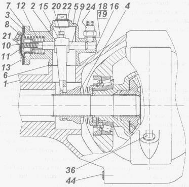
 The center differential is mounted in the crankcase (Figure 4.23), which is attached to the crankcase of the main transmission of the middle axle. It consists of a bevel differential proper, a locking mechanism and a locking control drive.
The differential housing 5 consists of two halves (cups) that are bolted together. The front cup has a shank that is supported by a ball bearing 29. A flange / is installed on the splined part of the shank, connecting the differential housing by a cardan gear with the gearbox. A cross is clamped between the body halves 26, on the thorns of which four satellites are installed 6 with support washers 7. The satellites mesh with the gears 24 and 27 drive of the middle and rear axles. Since the satellites act on the teeth of these gears with equal forces and their dimensions are the same, the torques on the gears of the drive of the middle and rear axles are also the same, that is, the differential is symmetrical.
Gear 27 of the rear axle drive is installed in the bore of the differential housing, a support washer is placed under its end 28, there is a drill in the housing for supplying oil to the support washer and the gear hub. The splines made on the inner surface of the hub, the gear 27 connects to the splined end of the drive shaft of the rear axle drive. Gear 24 drive of the middle axle by means of splines made on the inner surface of the hub, is connected to the elongated hub of the driving bevel gear of the main gear of the middle axle. At the end of the gear hub 24 a toothed clutch is installed on the splines 21, on the outside of which the coupling can move 22 center differential lock. This clutch fork 20 connects to the slider 11, associated with the diaphragm lock control mechanism. Frame 19 the locking mechanism is attached to the center differential housing. Between body and cover 18 rubber diaphragm clamped 15. The cavity behind the diaphragm (on the side of the cover) is connected with a hose 16 with a valve for activating the differential lock. A slider is placed in the cavity under the diaphragm 11, glass-connected 14, inside which there is a pressure spring 13, a outside - return spring 12.
The lever of the center differential lock activation valve is located on the instrument panel in the car cab. There is also a center differential lock warning lamp on the instrument panel.
In the position shown in fig. 4.23, the center differential is unlocked. For the differential lock, the lever of the switch-on valve, located on the instrument panel, is shifted by the driver to the right position. In this case, compressed air from the control valve through the pipeline system and hose 16 enters the cavity between the housing cover and the diaphragm, which bends, moves the glass 14 and slider 11 forward, overcoming the resistance of the return spring 12. With the beginning of the movement of the slider, the contacts of the switch 8 are closed, and the control lamp on the instrument panel lights up. Together with the crawler
the fork mounted on it moves 20, which introduces the clutch 22 meshes with the ring gear on the differential housing. At the extreme left position of the clutch, the gear 24 the drive of the middle axle and the housing 5 of the differential are rigidly connected, that is, the differential becomes locked and the gears 24 and 27 the axle drives are forced to rotate at the same frequency.
To unlock the center differential, the control valve lever on the instrument panel must be moved to the left position. In this case, the cavity behind the diaphragm of the differential lock mechanism through the control valve and pipelines will be connected to the atmosphere. Under the action of the return spring, the diaphragm and the slider with the fork move to the right (back), simultaneously displacing the lock-up clutch so that it disengages from the gear rim of the differential housing.
1.4. The device and operation of the main gears and interwheel
differentials of driving axles.
Carter final drive 3 (Fig. 4.24) is bolted to the bridge beam. The plane of the connector is sealed with a paronite gasket 0.8 mm thick. A pair of cylindrical gears with helical teeth are installed in the crankcase cavity. Bevel drive gear 13 installed on the splines of the drive through shaft 15 (for the middle bridge). This shaft is supported by two tapered roller bearings 12 and 18, which are closed by covers with shims // and 16. The output shaft ends are sealed with self-tightening seals, protected by dirt baffles. At the ends of the through shaft (for the middle axle), flanges of cardan joints are installed 10, 17. Flange 17 drive to the rear axle is smaller than the flange 10, to which the torque is supplied from the center differential of the transfer case.
The intermediate shaft 9 of the main gear is mounted on a cylindrical roller 2 and two tapered roller bearings 6, mounted in the cup 5. Shims 7 and 8 are supplied under the cup flange and the bearing cover. 4 made integral with the intermediate shaft, and

driven bevel gear / pressed onto
the end of this shaft and is additionally secured to it with a key. Driven spur gear 22 connected to the halves (cups) of the differential housing, each of which is supported by a tapered bearing.
The crosspiece is located in the differential housing 21, four satellites 20 on bushings 25, two side gears 19, under which support washers are installed 23. Half-axle gears are connected by splines with wheel drive half-shafts. The differential is symmetrical and distributes the torque almost equally between the right and left wheels.
The main gear and differential of the front and rear axles have a similar structure. Each of these axles has one flange on the drive shaft cardan joint from the side cardan transmission, and from the outside, the ends of the shafts are closed with covers.
1.5. Basic adjustments of the final driveand differential
In the main gear, the tightening of the tapered bearings of the driving bevel gear (KamAZ-5320), bearings of the drive through shaft, tapered bearings of the intermediate shaft and the interwheel differential housing are regulated. The bearings in these assemblies are preloaded. When making adjustments, the preload must be checked very carefully to avoid malfunctions, since too tight the bearings will overheat and fail.
The main gears also provide the ability to adjust the meshing of the bevel gears. However, it must be borne in mind that it is impractical to adjust the operating pair during operation. It is carried out with a repair or a new set of a pair of bevel gears when replacing a worn pair. Adjustments of bearings and engagement of bevel gears are carried out on the main gear removed from the vehicle.
The bearings of the drive bevel gear of the main drive of the middle drive axle of the KamAZ-5320 vehicle are adjusted by selecting the required thickness of two adjusting washers (see Fig.4.21), which are installed between the inner ring of the front bearing and the spacer sleeve. After installing the adjusting washers, the fastening nut is tightened with a torque of 240 Nm (24 kgf "m). When tightening, turn the drive gear 20, so that the rollers are in the correct position in the bearing races
Then the locknut is tightened with a torque of 240-360 Nm (24-36 kgf-m) and fixed. The value of the bearing preload is checked by the torque required to turn the drive gear. When checking, the torque of resistance to turning the drive gear in the bearings should be 0.8-3.0 N-m (0.08-0.30 kgf-m). It is necessary to measure the moment of resistance with a smooth rotation of the gear in one direction and after at least five full revolutions. In this case, the bearings must be lubricated.
Adjustment of the bearings of the leading bevel gear of the main gear of the rear drive axle of the KamAZ-5320 vehicle (see Fig. 4.22) is carried out by selecting the required thickness of the adjusting washers, which are installed between the inner race of the front bearing and the support washer. The moment of resistance to turning the drive gear shaft should be 0.8-3.0 Nm (0.08-0.30 kgf-m). When checking this moment, the bearing cup cover must be moved towards the flange so that the oil seal does not resist rotation. After the final selection of adjusting washers, the nut of the universal joint flange is tightened with a torque of 240-360 Nm (24-36 kgf-m) and pinned.
Tapered roller bearings (see Fig. 4.21) of the intermediate shaft of the main transmission of the KamAZ-5320 vehicle are adjusted by selecting the thickness of two adjusting washers, which are installed between the inner bearing races. The moment of resistance to turning the intermediate shaft in the bearings should be 2-4 Nm as when adjusting the bearings of the pinion gear.
Differential housing tapered roller bearing preload adjustment using nuts 8. Prev: the preload is controlled by the amount of crankcase deformation when tightening the adjusting nuts. When adjusting, pre-tighten the cover bolts 22 moment 100-120 Nm (10-12 kgf-cm). Then, by tightening the adjusting nuts, the bearing preload is ensured, at which the distance between the ends of the bearing caps increases by 0.1-0.15 mm. The distance is measured between the platforms for the stoppers of the differential bearing nuts. In order for the rollers in the bearing races to occupy the correct position, the differential housing must be turned several times during the adjustment process. When the required preload is reached, the adjusting nuts are locked, and the bearing cap fastening bolts are finally tightened with a torque of 250-320 Nm (25-32 kgf-m) and also locked.
When adjusting the tapered roller bearings of the main gear and the differentials of the driving axles of the Ural 4320, the main gear with the differential and cardan flanges removed is installed in the device. All tapered roller bearings of the main drive are adjusted with preload, just like on the KamAZ-5320. Bearing adjustment 12, 18 (see Fig.4.24) the drive through shaft is carried out by changing the thickness of a set of shims 11 and 16. When properly adjusted
bearings, the moment of resistance to turning of the drive through shaft should be 1-2 Nm (0.1-0.2 kgf-cm). The bearing cap fastening bolts must be tightened with a torque of 60-80 Nm (6-8 kgf-m).
Bearing adjustment 6 the intermediate shaft is carried out by changing the thickness of the set of shims 8 under the bearing cap. By sequentially removing the gaskets, the clearance in the bearings b is selected, after which another gasket with a thickness of 0.1-0.15 mm is removed. The moment of resistance to turning the intermediate shaft should be equal to 0.4-0.8 Nm (0.04-0.08 kgf-m). Removing the gaskets from under the bearing cover shifts the driven gear towards the driving gear and leads to a decrease in the lateral clearance in the engagement, therefore it is necessary to install the removed gaskets under the bearing cup flange 5 into the set of gaskets 7 and thereby restore the position of the driven bevel gear relative to the leading one. Tighten the bearing cap bolts with a torque of 60-80 Nm (6-8 kgf-m).
After adjusting the bearings of the drive through and intermediate shafts, it is advisable to check the correct engagement of the bevel gears "on the paint". The imprint on the tooth of the driven gear should be located closer to the narrow end of the tooth, but not reach the edge of the tooth by 2-5 mm. The length of the impression should not be less than 0.45 times the length of the tooth. The lateral gap between the teeth at their widest part should be 0.1-0.4 mm. Gear adjustment
Similar abstracts:
The device of the four-speed gearbox of the Volga car. Maintenance during operation. The procedure for removing the gearbox, possible malfunctions and their elimination. Disassembly stages input shaft and gearshift mechanism.
Appointment and general characteristics steering of the KamAZ-5320 car and the MTZ-80 wheeled tractor with a hydraulic booster. Basic steering adjustments. Possible malfunctions and maintenance. Hydraulic booster pump.
Studying the characteristics of the bus, such as body structure, seat layout, engine location. Bus transmission properties, wheels and tires. Steering and electrical equipment. Torque generated on crankshaft engine.
General information, diagnostics and repair of gearbox crawler tractor... Classification of gear transmissions. Major defects in gearboxes, shafts, axles, gear wheels, levers and shift forks. Safety precautions before starting the diesel engine.
Transfer case and additional gearbox. Crawler gear in transfer case car. Purpose and types of steering mechanisms. Working drive circuit brake system car GAZ-3307. Appointment and general arrangement heavy-duty trailers.
Rear driving axleThe rear drive axle has a double spaced main gear, consisting of a central bevel gearbox and planetary wheel gears located in the wheel hubs. The rear axle reducer consists of a pair of bevel gears with circular teeth and an interwheel differential with a forced locking mechanism. Torque is transmitted to the drive bevel gear through the flange. The wheel drive is a planetary gearbox consisting of spur gears with external and internal gearing. The pinion gear is mounted on the axle splines.
Medium drive axle
The middle drive axle consists of a central reduction gear and planetary wheel gears installed in the wheel hubs. The gearbox of the middle axle consists of a pair of cylindrical gears, an interaxle differential, a pair of bevel gears with circular teeth and an interwheel differential. Torque from cardan shaft through the axle drive shaft is transmitted to the center differential crosspiece, which distributes the torque to the middle and rear axle s in a ratio of 1: 1 and has a mechanism for a forced differential lock.
Inter-axle and cross-axle differential locks are activated by the keys on the instrument panel in the car cab, the control drive is electropneumatic.
Differential locks use rules
Differential locks can significantly increase the vehicle's off-road capability on slippery or muddy roads. The presence of interwheel blocking allows you to move in conditions when the drive wheels from different sides of the car are on surfaces with different grip coefficients, which causes them to slip.
It should be remembered that the use of locks significantly increases the load in the transmission, since the locked differential does not have the function of speed separation and cannot ensure the movement of the drive wheels at different speeds, which is necessary when cornering or maneuvering.
Attention! When the cross-axle differentials are locked, only STRAIGHT movement of the car is allowed, violation of this rule can lead to breakage of the differentials!
Attention! The inclusion of locks is allowed only when driving on a slippery or muddy road. The use of interlocks on hard and dry surfaces is prohibited!
Attention! When the locks are on, driving the car becomes harder, the car becomes less maneuverable and more "straightforward" - this means that you should drive the car with extreme caution!
The procedure for turning on and off differential locks
A warning:
Differential locks increase the vehicle's cross-country ability. At the same time, they must be turned on in advance before overcoming a difficult-to-pass section, and not at the moment when the car has already lost its mobility.
Locks should be engaged before overcoming a difficult area and disabled IMMEDIATELY after driving onto a hard or dry surface! Activate and deactivate the differential locks only on a STILL vehicle. It is forbidden to turn on and off the locks while driving!
If the drive wheels slip when driving on dirty or slippery surfaces, you must turn on the differential locks.
Attention:
Engaging the INTER-WHEEL differential lock is allowed only AFTER enabling the INTER-WHEEL differential lock.
Engage the blocking of the center differential of the middle and rear axles in the following order:
4. Engage the appropriate gear in the gearbox, engage the clutch by releasing the pedal, and continue driving.
If, when the lock is turned on, the differential is not blocked, and the corresponding warning lamp does not turn on, you must slowly start moving the car. Wait until the differential locks and the warning lamp turns on, then start driving on a difficult-to-pass area.
If the blocking of the center differential of the middle and rear axles is not enough for the movement of the car, then it is necessary to turn on the blocking of interwheel differentials:
1. Completely stop the vehicle, set the gear lever to neutral.
2. Disengage the clutch by pressing the pedal all the way down.
3. With the clutch disengaged, turn on the center differential lock of the middle and rear axles, while the sound signal (buzzer) and the corresponding warning lamp turn on.
4. With the clutch disengaged, turn on the blocking of the cross-axle differentials of the middle and rear axles, while the corresponding warning lamp turns on.
5. Engage the appropriate gear in the gearbox, engage the clutch by releasing the pedal, and continue driving.
If, when the lock is turned on, the differentials are not blocked, and the corresponding warning lamp does not turn on, you must slowly start moving the car. Wait until the differentials are locked and the warning lamp comes on, then start driving on difficult terrain.
Attention:
It is forbidden to turn on the inter-axle differential locks when the inter-axle differential lock is off!
After overcoming difficult terrain, immediately disengage the differential locks in the following order:
1. Completely stop the vehicle, set the gear lever to neutral.
2. At minimum speed idle move disengage the clutch by pressing the pedal all the way down, turn off the differential locks with the appropriate switches. In this case, the corresponding indicator lamps must go out. Deactivate interlocks in the reverse order of activation:
1) cross-axle differentials of the middle and rear axles;
2) center differential of the middle and rear axles.
The location of the electro-pneumatic control valves on the car
The installation location of the block of electro-pneumatic valves for controlling transmission units is shown in the figure:
A - the place of installation of the block of solenoid valves for controlling inter-axle and inter-axle differential locks.
 Solenoid valve block:
1 - control valve for inter-axle blocking of the middle and rear axles
2- control valve for interwheel blocking of the middle and rear axles
Locking Precautions
1. Do not engage locks when driving on roads with hard and dry surfaces, the lock should be used only when driving on mud or slippery ground.
2. On roads with muddy or slippery surfaces, engage differential locks, do not allow the drive wheels to slip when the lock is disabled, even for a few seconds - this can lead to damage to the drive axle gearbox parts.
3. It is forbidden to engage the blocking of cross-axle differentials during slipping of one of the wheels. Do not allow the vehicle to move on cobblestones or paved roads with the cross-axle differential lock engaged - this can damage the gears!
4. Engage and disengage the differential locks only after the vehicle has come to a complete stop with the clutch disengaged (with the clutch pedal depressed all the way)!
5. When driving a loaded vehicle uphill reverse engaging the center differential lock is mandatory!
6. If it is necessary to use the differential locks at the same time, first engage the center lock and only then the cross-axle differential lock!
7. It is forbidden to engage the inter-axle differential lock when the inter-axle differential lock is off!
8. It is forbidden to engage differential locks by simultaneously pressing both control keys!
9. Engage the differential locks in advance of overcoming difficult terrain and turn off immediately after driving on hard and / or dry surfaces.
10. Maximum speed movement with the included locks of interwheel and center differentials no more than 40 km / h.
11. When the differential locks are engaged, only straight-line movement of the vehicle is allowed! When maneuvering or turning the vehicle, parts of the differentials may break!
12. When the locks are on, driving the car becomes harder, the car becomes less maneuverable and more "straightforward" - you should drive the car with extreme caution!
13. Periodically check the oil level in the drive axle gearboxes. Remember that a lack of oil can damage the differential parts!
1. MAIN GEAR AND DRIVING AXLE DIFFERENTIAL
1.1. The purpose of the drive axle mechanisms
Each drive axle is equipped with a main gear and an inter-wheel differential. In addition, a center differential is installed on the middle drive axle of the KamAZ-5320 car.
The main gear of the car is designed to constantly increase the torque supplied from the engine and transmit it at right angles to the drive wheels.
The constant increase in torque is characterized by the final drive ratio.
On KamAZ vehicles, depending on the purpose, the gear ratio of the main gear is 5.43; 5.94; 6.53; 7.22. On the Ural-4320 car, it is 7.32. On modifications of cars intended for use as truck tractors, the gear ratios of the main drive are increased.
On the KamAZ-5320, double main gears are used, consisting of two gear pairs, a pair of bevel gears with spiral teeth and a pair of spur gears with oblique teeth. This scheme allows you to get a large gear ratio with sufficient ground clearance under the main gear housing.
The differential installed in the drive axle housing is called the interwheel differential.
It is designed to distribute the torque supplied from the main gear between the right left driving wheels and provides the ability to rotate the wheels at different frequencies, which is necessary to prevent the wheels from slipping when the car is moving around bends and on uneven roads when the wheels are located on different sides of the car. go uneven paths.
On the KamAZ-5320, a conical symmetric differential is used in each drive axle. This means that bevel gears are used in the differential and the same torques are transmitted to the right and left wheels from it.
A center differential is installed on the middle drive axle of the KamAZ-5320 vehicle. It allows the drive shafts of the main gears of the middle and rear axles to rotate at different frequencies, and therefore, the wheels of these axles can also rotate at different frequencies. The center differential of the KAMAZ-5320 car is conical, symmetrical, lockable. When the differential is not locked, it distributes torque between the main gears of the middle and rear driving axles almost equally. Differential coupling provides a more uniform loading of drive parts to the drive wheels, reduces tire wear, and improves vehicle handling. However, as already noted, in difficult conditions and on slippery roads, it negatively affects the vehicle's passability. Under these conditions, the differential is blocked, the drive shafts of the main gears of the driving axles are rigidly connected
rotate at the same frequencies. At the same time, the slipping of the driving wheels is reduced, and the vehicle's cross-country ability is improved.
1.2. The device and operation of the main gearsand cross-axle differentials of the leadingbridges of the KAMAZ-5320 car
The double main gear of the middle drive axle of the KamAZ-5320 car (Fig. 4.21) is made with a through shaft to drive the main gear of the rear axle. The leading bevel gear 20 is installed in the throat of the main drive housing on two tapered roller bearings 24, 2b, between the inner races of which there is a spacer sleeve and shims 25. The ground end of the hub of this gear is connected to the bevel gear of the center differential, and the drive shaft 21 passes inside the hub , one end connected to the bevel gear of the center differential, and the other by means of a cardan transmission with the drive shaft of the main gear of the rear axle.
The intermediate shaft is supported by one end on two tapered roller bearings 7, between the inner races of which there are adjusting washers 4, and the other on a roller bearing installed in the bore of the bulkhead of the main gear housing. Tapered roller bearings 7 fix the intermediate shaft against displacement in the axial direction. Along with the intermediate shaft, the driving cylindrical gear 3 with oblique teeth is made. Driven bevel gear / pressed onto the end of the intermediate
cylindrical gear 16. Torque from the interwheel differential housing, to which the driven cylindrical gear 16 of the main gear is attached, is transmitted to the crosspiece 15, and from it through the satellites to the gears of the axle shafts. The satellites, acting with the same force on the right and left gears of the axle shafts, create equal torques on them.
At the same time, due to insignificant internal friction, the equality of moments is practically preserved both with stationary satellites and with their rotation.
Turning on the spikes of the cross, the satellites provide the ability to rotate the right and left axle shafts, and, consequently, the wheels with different frequencies.
The rubbing surfaces of the main gear and differential parts are lubricated by spraying oil in the crankcase. The lubricant enters the differential through the windows in its housing, and longitudinal and radial channels are provided for supplying oil to the tapered bearings of the driving bevel gear and the intermediate shaft in the glasses in which the bearings are installed. The cavity of the crankcase of the main gear is communicated with the atmosphere through the vent cap (breather). The shafts are sealed with self-tightening seals, protected by dirt baffle rings.
The general arrangement of the main gear and the rear drive axle differential (Fig. 4.22) is similar to that discussed above. The differences are mainly due to the fact that the rear  the drive axle is not through and receives torque from
center differential installed on the middle drive axle.
In the main gear of the rear axle, the drive bevel gear 21 differs from the similar gear of the middle axle in that its hub is shorter and has internal splines for connecting to the drive shaft 22 of the main gear of the rear axle. Tapered roller bearings 18 and 20 are interchangeable with the corresponding center drive axle bearings. The drive shaft of the main drive of the rear axle with its rear end rests on one roller bearing installed in the bore of the crankcase. There is a channel in the throat of the crankcase for the circulation of the lubricant near the bearing. The bearing is closed from the end with a cover. The rest of the details of the main gear and the cross-axle differential of the middle and rear driving axles are similar in design.
1.3. Design and operation of the center differentialvehicle KamAZ-5320
 The center differential is mounted in the crankcase (Figure 4.23), which is attached to the crankcase of the main transmission of the middle axle. It consists of a bevel differential proper, a locking mechanism and a locking control drive.
Rear driving axle trucks Kamaz-4308 (Fig. 26 and 27) - with main gear with a gear ratio of 4.01.
Cross-axle differentials of the rear axle Kamaz-4308 are tapered with four satellites located in the wheel hubs, with a cross-axle differential lock, with automatic adjusting levers.
The control of the cross-axle differential is pneumatic, carried out by a lever (crane) located on the instrument panel. Possibility of installation is provided anti-lock braking system(ABS).
The driving axles of Kamaz-4308 contain the main gears, which are fixed in the crankcase of 9 axles with the help of nuts and studs, of which 27 conical expansion sleeves are installed on four of them.
On the axle housing there are spring supports 13, wheel hubs 29 connected to brake discs 2 and brake mechanisms 17, which are bolted to the flange of the axle housing.
The transmission of torque from the central main gear to the wheels is carried out using completely unloaded from axial load axle shafts 8 and 12.
Rice. 26. Rear axle Kamaz-4308
1 - sensor bracket; 2 - brake disc; 3 - sensor; 4 - safety valve; 5 - main gear case; 6 - nut for securing the main drive housing; 8 - right semiaxis; 9 - rear axle housing; 11 - magnetic drain plug; 12 - left semiaxis; 13 - spring support; 16 - brake chamber type 20/24; 17 - brake mechanism; 18 - cuff; 19, 20 - tapered roller bearing; 21 - lock washer; 22 - folding washer; 23 - bearing nut; 24 - axle shaft mounting stud; 25 - spring washer; 26 - nut; 27 - sleeve expanding the axle shaft; 28 - semiaxis gasket; 29 - rear wheel hub.
The main transmission of the rear axle Kamaz-4308 (Fig. 27) is single-stage, consists of a pair of bevel gears with spiral teeth, an interwheel differential and a rear axle reducer housing.
The driving bevel gear 2 is mounted on two tapered bearings. An adjusting sleeve 23 is located between the inner rings of the bearings.
One of the bearings is located in a glass 6, fixed with bolts 58 to the housing 1 of the gearbox of the rear axle Kamaz-4308. Shims 9 are installed between the end surfaces of the gearbox housing and the flange part of the glass.
The cavity of the glass is closed from the outside with a lid into which a two-edged cuff is pressed. A flange for attaching the propeller shaft is installed on the spline end of the driving bevel gear 2. The flange is tightened with a self-locking nut.
The adjustment of the gearing in the bevel gear pair of the rear axle gearbox KamAZ-4308 is carried out by adjusting shims 9.
The preload of tapered bearings in the drive and driven gear assemblies is performed by selecting the linear dimensions of the adjusting sleeves 16 and 23, and the tapered differential bearings - using adjusting nuts 24 and 48.
The interwheel differential of the rear axle Kamaz-4308 (Fig. 27) is conical, symmetrical, lockable. The blocking control is electropneumatic, carried out by a crane on the instrument panel.
It is possible to engage the cross-axle differential locking mechanism only on a slippery section of the road. Switch on when stopping the Kamaz-4308 vehicle or when driving slowly in a straight line directly in front of a slippery section of the road. The lock should be turned on and off when the clutch pedal is depressed.

Rice. 27. Transmission of the main gearbox of the rear axle KamAZ-4308
1 - gearbox housing; 2 - driving shaft; 3 - differential assembly; 4 - driven gear; 5, 6 - a glass of bearings; 7 - gasket; 8 - flange; 9 - adjusting gaskets; 10 - nut; 11, 20 - differential roller bearings; 12 - semi-axial bevel wheel; 13 - satellite; 14 - cover
bearing cups; 15 - support washer; 16, 23 - adjusting bushings; 18 - differential cup; 19 - crosspiece; 21 - support washer; 47 - gearbox bracket; 24, 48 - bearing nuts; 49 - bearing nut stopper; 56 - tapered roller bearing; 58, 59, 61 - bolt.
The differential of the rear axle KamAZ-4308 is mounted on two tapered roller bearings 11 and 20, located in the gearbox housing 1. The differential contains cups 3 and 18, inside of which there are two bevel semi-axial gears 12 meshing with four satellites 13.
Satellites 13, with pressed-in bronze bushings, are mounted on the spikes of the crosspiece 19, which is rigidly fixed in the cups 3 and 18 of the differential.
Support washers 21 are placed under the ends of the semi-axial gears 12 and satellites 13. The washers are installed with grooves towards the semi-axial gears, and with a flat surface towards the cups.
The locking mechanism for the rear axle cross-axle differential (Fig. 28) is designed to increase the cross-country ability of the Kamaz-4308 vehicle in off-road conditions and improve its traction on slippery roads by distributing torque between the rear drive axle shafts.
The mechanism consists of gear couplings 4, a rod 9 with a fork 2, a membrane pneumatic chamber and a control valve. It is possible to engage the interwheel differential locking mechanism only when the vehicle is stopped or when the vehicle is moving slowly.
Rice. 28. The mechanism of blocking the interwheel differential of the rear axle KamAZ-4308
1 - rear axle housing; 2 - blocking fork; 3 - cover of the body of the locking mechanism; 4 - interwheel differential lock clutch; 5 - blocking mechanism body; 6 - body gasket; 7 - diaphragm of the locking mechanism; 8 - glass of the locking mechanism; 9 - the rod of the mechanism
blocking; 10 - returnable spring; 11 - cover of a glass of the locking mechanism; 12 - pressure spring; 13 - bolt; 15 - low nut; 16 - expanding plug; 18 - adjusting gasket; 19 - sealing gasket; 20 - adjusting screw; 21 - persistent ring; 22, 36 - plug KG 1 "; 24 - switch; 44 - magnetic plug.
Rear axle housing KamAZ-4308 - welded from stamped steel beams. A crankcase cover, a flange for attaching the final drive, end flanges for attaching brake calipers, levers for attaching jet rods and springs are welded to the crankcase beams.
The crankcase trunnion is friction welded to the beams. Drive axle half-shafts are completely unloaded.
The hubs 7 (Fig. 26) of the rear wheels of Kamaz-4308 are mounted on tapered roller bearings 19 and 20 and rest on the journal of the axle housing. The hub bearings are adjusted using an adjusting nut 23, which is prevented from turning by means of a lock washer 21 and a bend washer 22.
To the hubs of 29 wheels with special wheel bolts with nuts attached brake discs 2 and wheel discs. Bearings 19 and 20 of the hub are protected from dirt and dust by two cuffs 18.
In the crankcases of the main gear of the rear axle gearbox Kamaz-4308 there are 11 filler and drain holes, closed with plugs. To equalize the pressure inside the axle crankcase, a safety valve 4 is installed in the upper part of the crankcase.
Maintenance of the rear drive axle Kamaz-4308
At maintenance rear driving axle KamAZ-4308 the following operations are performed:
Check the condition of the wheel hub bearings by hub heating;
Fasten the nuts 6 (Fig. 26) securing the final drive housing to the axle housing;
Check and top up the oil level in the drive axle housing.
Fasten nut 10 (Fig. 27) of the drive axle pinion shaft flange;
Change the oil in the drive axle crankcase Kamaz-4308;
Check the tightness of welded, flanged and threaded connections rear axle. Oil leakage is not allowed;
Check the operation of the cross-axle differential locking mechanism. When the lock is turned on, the indicator on the instrument panel should light up;
Check the condition of the bearings of the KAMAZ-4308 wheel hubs (with the hubs removed). Rollers and bearing races must be free of visible pits and cracks. The rollers must not fall out of the separators;
Additionally, in the fall, change the oil in the drive axle crankcase (after 50 thousand km, but at least once a year).
The heating of the hubs is checked by hand. If the hand cannot bear it, the heating of the hub is considered unacceptable and it is necessary to adjust and lubricate the hub bearings.
To check the rear axle KamAZ-4308 for tightness, it is necessary to supply air through the threaded hole under the safety valve of the axle crankcase with an overpressure in the crankcase of 19.6-24.5 kPa (0.20-0.25 kgf / cm2).
Leakage of oil through the cuffs, joints and welds on the axle housing is unacceptable (slight formation of oil spots on the surfaces in the above zones, except for the welded seams, without dripping is not a rejection sign).
To check the oil level, unscrew the control hole plug on the rear axle final drive housing. If there is no leakage of oil from the control hole, then it is necessary to add oil to its level through the filler hole.
To change the oil in the main gear and the crankcase of the Kamaz-4308 bridge, it is necessary to drain the used oil when it is still warm from heating during operation. Drain the oil through the drain hole by unscrewing the inspection and filler plugs.
The amount of oil to be poured in in accordance with the chemical chart. After draining the oil, remove metal deposits from the magnetic drain, inspection and filler plugs and refit them.
Flush the safety valves of the drive axles diesel fuel followed by blowing with compressed air.
The oil level in the gearbox housing of the rear axle KamAZ-4308 should reach the lower edge of the control hole. The control should be carried out after the bridges have been at rest for at least one hour.
To replace the grease in the wheel hubs (with the hub removed), it is necessary to remove the old lubricant, rinse the inner cavity of the hub, bearings, nuts and washers with kerosene.
Apply lubricant between the rollers and bearing cages evenly around the entire circumference and in the cavity of the hub between the bearing races. After replacement lubricant adjust the bearings of the rear wheel hubs KamAZ-4308.
To check the fastening of the input flange of the main gear of the rear axle, put the car on an inspection pit or overpass and place stops under the wheels.
Then turn off parking brake, set the gear lever to neutral. Swing the flange of the shaft in the longitudinal and transverse directions by hand. If there is a noticeable gap, disconnect the propeller shaft and eliminate the movement of the flange.
To do this, it is necessary to disconnect the Kamaz-4308 propeller shaft, unscrew the flange fastening nut, remove the flange, cover and reduce the thickness of the shims 9 (Fig. 27) by no more than 0.1 mm.
In this case, gaskets with a thickness of 0.05 mm should remain at the edges of the package of gaskets. Then fix the cover in the gearbox housing, install the flange and tighten nut 10 to 588-686 Nm (60-70 kg / cm).
To adjust the bearings of the rear wheel hubs of the KamAZ-4308, you need to hang the wheels and do the following:
Tighten the bearing retaining nut before the hub starts to brake, turning it in both directions so that the bearing rollers take the optimal position;
Unscrew the nut by about 1/6;
Bend the tabs of the lock washer to the edge of the nut.
Repair of the rear axle of the Kamaz-4308 car
When repairing, depending on the malfunction, dismantle the drive axle assembly, or only the final drive.
Disassemble the rear axle gearbox Kamaz-4308 into the following assembly units, after draining the oil from the rear axle crankcase into a clean dish (for its further use):
Leading bevel gear;
Interwheel differential;
Driven bevel gear;
When disassembling, be sure to check the backlash in the above assembly units, since the assembly must be provided with the mandatory preload of tapered bearings. After complete disassembly, flush and check the gearbox parts.
When disassembling the rear axle KamAZ-4308, it is imperative to check the axial and radial displacements in the assembly units of the main gear, since the assembly must provide mandatory preload of tapered bearings.
When examining the details of the rear axle KamAZ-4308, you should:
Check the teeth and the location of the contact patch on the working surfaces of the bevel gear teeth; if unacceptable wear or damage (tooth chipping) is found, replace with new ones.
If the teeth are not properly meshed, find the cause and eliminate it. For spare parts and for assembly, the driving and driven spiral bevel gears are supplied with a set matched for noise and contact patch, therefore, if one of them is damaged, both wheels must be replaced;
Check in the interwheel differential of the Kamaz-4308 bridge the condition of the surfaces of the spikes of the crosspieces, the bushings of the satellites, the surfaces of the support washers of the satellites and half-axle gears, the landing and end surfaces of the half-axle gears and their mounting locations in the differential cups.
In case of minor damage, the surfaces can be polished with a fine-grained sandpaper, and with serious damage replace parts with new ones.
Inspect all bearings. They should be wear-free, with smooth working surfaces.
To disassemble the hub (Fig. 26) it is necessary to unscrew the nuts 26 securing the axle shaft and remove the axle shaft. Unscrew nut 23 of the bearing and remove the inner bearing race 20.
Unscrew the mounting bolts and remove the KamAZ-4308 wheel hub assembly with a brake disc. Outer rings of bearings, oil seals should be dismantled in case of replacement.
The assembly of the hub must be carried out in the reverse order. Before assembly, grease the seating surfaces on the axle stub. After installing the hub 7, it is necessary to adjust the bearings 19 and 20 of the hub.
To do this, tighten the bearing fastening nut 23 with an approximate torque of 245 ... 294 Nm (25 ... 30 kg / cm) before the hub starts to brake, while turning the hub in both directions, so that the rollers are correctly installed on the tapered surfaces of the rings.
Then loosen the nut about 1/6 of a turn. Bend one ledge of the bend washer to the edge of the nut. Check the rotation of the hub. The hub should rotate by hand freely without binding.
To remove the main gear, it is necessary to hang out the driving axle Kamaz-4308, fix it on stands, drain the oil from the axle housing, the main gear, unscrew the nuts securing the axle shafts and remove the axle shafts by about 150 mm on both sides.
After unscrewing the bolts securing the final drive to the axle housing, remove it.
To disassemble the driving bevel wheel of the main gear of the Kamaz-4308 axle reducer (Fig. 27), unscrew the nut 10 for fastening the flange, remove the flange 8. Unscrew the bolts 58 fastening the cover of the bearing cup 6 and remove the cover with the gasket.
Screwing in the technological bolts M12x1.25x50 (2 pcs.), Press the drive bevel gear assembly out of the gearbox housing 1.
To disassemble the unit, it is necessary to remove the inner ring of the outer bearing, the adjusting sleeve 23 and then the driving bevel gear with the inner ring of the inner bearing. Press the inner race of the tapered inner bearing with a puller.
To remove, install the edges of the wedges 8 of the puller (Fig. 29) between the inner bearing ring and the wheel and, screwing in the screw 6 and the crosshead 7, pull them off.
Insert the grippers 1 by the wedges 8 and fix them in this position with the screw 3. Resting the tip 2 against the wheel end and screwing the screw 3 into the traverse 4, remove the ring.
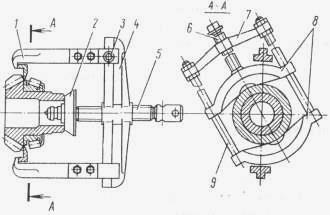
Fig. 29. Remover of inner rings of bearings of driving gears and differential cups of the rear axle KamAZ-4308
1 - capture; 2 - tip; 3, 5 and 6 - screws; 4, 7 - traverses; 8 - wedge; 9 - rack.

Rice. 30. Removing the inner ring of the differential bearing Kamaz-4308
1 - capture; 2 - tip; 3 and 5 - screws; 4 - traverse.
To disassemble the differential of the rear axle Kamaz-4308 (Fig. 27), unscrew the bolts securing the bearing caps, remove the covers and adjusting threaded nuts 24 and 28. Remove the differential from the main gear.
To do this, insert the grips 1 (Fig. 30) behind the inner bearing ring and fix with screws 3. Resting the tip 2 against the end of the differential, screw the screw 5 into the yoke 4 until the inner bearing ring is completely removed.
After unscrewing the bolts of the Kamaz-4308 differential cups, disconnect the cups. Remove the crosspiece 16 with satellites 15 and support washers 17, semi-axial gears 12 with support washers 13.
Clean the removed parts and check them technical condition... If there is increased wear or galling marks on the surface of the bushings, they should be replaced.
Replace cups only as a set (both cups must have the same set number). After replacing the cups, before assembling the differential, you need to press on the inner bearing rings 20.
When assembling the differential, it is necessary to install in the right differential cup of the Kamaz-4308 drive axle a right semi-axial gear with a washer, a crosspiece assembled with bushings, satellites and washers.
Insert support washers, left axle wheel into the left cup. Align differential cups with factory markings. Tighten both cups with self-locking bolts to a torque of 98-122 Nm (10-12.5 kg / cm).
The self-locking bolts of the driven bevel gear must be tightened to 245-294 Nm (25-30 kg / cm).
Install cross-axle differential in final drive housing. Tighten the bearing cap bolts to 100-120 Nm (10-12 kg / cm).
When assembling the crankcase of the rear axle gearbox Kamaz-4308, it must be remembered that the differential bearing covers are not interchangeable, since they are processed assembled with the crankcase, so each cover must be installed in the place where it was located.
Assemble and install the assembly unit of the drive bevel wheel in the reverse order of its disassembly.
After installing the differential in the main gear housing, it is necessary to adjust the engagement of the driven and driving gears along the lateral clearance, which should be 0.25 - 0.40 mm and the contact patch.
The lateral clearance and the contact patch in engagement can be determined by simultaneously adjusting the location of the drive bevel gear 7 assembly and the differential.
Adjustment of the main gear of the gearbox of the Kamaz-4308 bridge (Fig. 27) includes adjusting the preload of the differential bearings and the bearings of the driving bevel gear, as well as adjusting the side clearance and contact patch of the bevel pair.
To ensure a preload in the tapered bearings of the drive bevel gear assembly in the presence of axial displacement, it is necessary:
Reduce the height of the adjusting bush 23 by grinding or replacing bushings from spare parts by the value of the axial displacement plus 0.04-0.06 mm;
Tighten nut 10 for fastening flange 8 to 588-686 Nm (60-70 kg / cm);
Check the turning force of the bearing sleeve 5, which should be equal to 10-24 N (1.00-2.50 kgf). It is necessary to measure the turning force with continuous rotation of the glass in one direction after at least five full turns.
In this case, the bearings must be lubricated, and the bearing cup cover must be shifted so that the collar does not resist the rotation of the gear wheels.
After installing the drive bevel gear of the differential into the housing of the KAMAZ-4308 gearbox, it is necessary to adjust the lateral clearance with nuts 24 and 48, which should be within 0.25-0.40 mm, and the contact patch of the bevel pair.
To adjust the bearings of the KAMAZ-4308 differential, tighten the adjusting nuts 24 and 48 evenly on both sides until the distance between the bearing caps increases by 0.1-0.2 mm.
After adjusting the bearings, you need to finally tighten the bearing cap bolts with a torque of 380-460 Nm (38-46 kg / cm) and lock them with lock washers.
Assemble the final drive of the bridge. Ensure the tightness of all flange and threaded connections that have access to the oil cavities with a sealant.
Replacing the rear axle Kamaz-4308
To remove the rear axle KamAZ-4308, you need to unscrew the plugs from the drain holes of the rear axle housing, wheel gears. Drain the oil.
After draining, clean and screw in the plugs. Use the parking brake to brake the vehicle and lift the rear section by the frame. Remove the wheels by unscrewing the wheel nuts.
Disconnect the compressed air supply air hoses from the brake chambers and chambers of the cross-axle differential lock. Disconnect the electrical wires from the lock engaging control sensors.
Unscrew the bolts of the KamAZ-4308 propeller shaft flange. Remove bolts and move propeller shaft to one side. Unscrew the nut securing the horizontal rod bracket of the brake force regulator and lay to the side.
Place the lift under the rear bogie with the drive axle and hang it out slightly.
Disconnect the upper torque rod from the axle housing. To do this, unscrew the bracket nuts, remove the spring washers. Pull the torque rod up.
Disconnect the lower reaction rods rear suspension Kamaz-4308. To do this, unscrew the nuts, spring washers and bolts of the lower left reaction rod. Take her aside. Repeat the same for the lower right torque rod.
Raise the rear of the vehicle. Roll out the lift with the drive axle from under the Kamaz-4308 car, place a stand under the frame and lower the car onto it. To install the drive axle, you must install it on a lift.
Raise the vehicle and place it on the support. Roll up the drive axle on a lift under the suspension.
Raise the axle with a hoist, and connect the suspension elements to the axle housing. The tightening torque of the bolts and nuts securing the upper and lower jet rods should be 435.1-490.5 Nm (44-50 kg / cm). Next, lower the lift rod and take it to the side.
Connect the rod of the brake force regulator to the drive axle Kamaz-4308 and fix it. Tighten the nut. Connect the propeller shaft to the drive axle flange, insert the bolts into the holes, putting on the spring washers and tightening the nuts.
Connect the compressed air supply air hoses to the brake chambers and chambers of the cross-axle differential lock.
Connect the electrical wires to the control sensors of the blocking activation.
Place the wheels on the hub, screw on the nuts and tighten them in a diagonal sequence to a torque of 540-670 Nm (54-67 kg / cm).
Check the stroke of the rear axle brake chambers, if necessary, adjust the brakes.
Unscrew filler plugs in final drive and wheel drives of rear axle. Fill in oil up to the level of the control hole. Screw in and tighten the filler plugs.
Check the operation of the drive axle by mileage. Overheating of wheel hub bearings and main gear bearings is not allowed.
The mod is installed on the gearbox of the middle KAMAZ axle and is one of the units that receives a sufficiently large load, which often puts it out of action. The center differential, one of the most fragile transmission units of the KAMAZ vehicle, is assembled as part of the gearbox of the middle axle.
The task performed by the center differential is to improve the vehicle's handling.
How does this happen? If the MOD is turned off, the rotation comes only to the rear axle, this saves the resource of the gearbox of the middle axle. The load on the axle is reduced, and accordingly the car becomes more economical.
If the MOD is turned on, it is blocked and the shafts of the drive axle reducers are connected, which increases the vehicle's cross-country ability. This can help with difficult road conditions, for example, with ice.
Also, the ability to disconnect the middle bridge using the MOD provides fuel savings. In rare cases, the gearbox of the middle axle may not be equipped with a mod, for example, on four-wheel drive vehicles a decrease in cross-country ability may not be necessary, therefore, there is often no center differential there.
Since the MOD completely takes all the torque and all the engine power on itself, it is subject to quite serious loads. Very often, the MOD fails due to the main cardan of the car, which is attached to it. For one reason or another, the main gimbal may have an imbalance. And this imbalance is a harmful load on the center differential.
Center differential malfunctions
One of the main reasons for the failure of the MOD is oil starvation. The MOD is located at the top of the middle gearbox. Because of low level oil in the bridge, it may receive less lubrication. This leads to increased wear and failure of the main gears, up to the rupture of the MOD in half.
Some of the malfunctions of the MOU can be determined independently. One of the main signs of improper operation of the MOD is the backlash that appeared on the flange of the MOD. Oil drips also indicate that attention should be paid to the work of the MOD. If the MOD overheats without oil, the paintwork burns on it.