To check the quality of manufacturing the surfaces of the teeth of involute cylindrical wheels, two types of control are very widely used in practice: measuring the size by rollers (balls) and measuring the length of the common normal.
Since to measure the length of the common normal, it is often enough to have only a vernier caliper, this method of controlling the thickness of the teeth is practically more accessible and is widely used, especially in the single (repair) production of cylindrical gears of a low degree of accuracy. At the same time, it should be noted that this control method is quite high accuracy due to the direct method of measuring the part, as opposed to measuring the size on rollers, which, by their tolerances, introduce an additional error. The length of the common normal refers to the parameters characterizing the lateral clearance rate in the gear train.
Consider external gearing. The calculation is regulated by GOST 16532-70. Measurements are performed in the plane of the normal (perpendicular) surface of the teeth. For helical gears (especially at large angles of inclination), it is necessary after calculations to make sure that the width of the wheel rim is "enough" for the measurement.
To simplify the calculation on the Internet, on the website www.al-vo.ru, a program was found in the form of a table MS Excel, which allows you to quickly find the length of the common normal of cylindrical gears, including helical gears with offset.
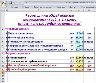
This program is convenient in that it allows you to quickly "in field conditions", if you have a smartphone or tablet, check the accuracy of field measurements of the existing gear, including for the possible presence or absence of displacements.
If you are working with KOMPAS-3D, then when calculating in the library "Shafts and mechanical transmission 2D "you will automatically receive the length of the common normal from the calculation results.
After completing the calculation, you must, taking a vernier caliper, measure the length of the common normal of the resulting number of teeth (several times and different groups) and get the values equal to the calculated one for a well-chopped wheel.
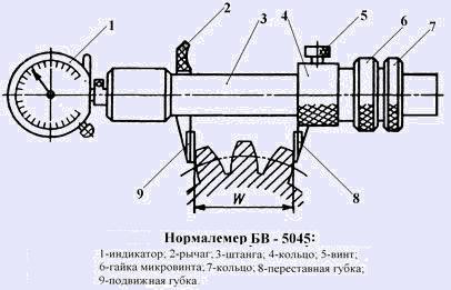
For the sake of fairness, it should be mentioned that to measure the length of the common normal, there is a special tool - the normal gauge. The standard gauge is made on the basis of a caliper or micrometer, supplying the latter with special convenient jaws for making measurements and a pointer indicator.
Tolerances of spur gears are regulated by GOST 1643-81. Including, tolerances are assigned to the length of the common normal, depending on the type of mating and the norm of the lateral clearance.
P.S. In reference books and in GOST, this calculation is written in such a way that “for two days you have to deal with beer,“ jumping ”from table to table”. Apparently in such cases, the authors have always done this to give themselves "the highest importance and significance" ... And ordinary students and engineers need to be "intimidated" with an abundance of transitions from page to page, so that on the fourth or fifth transition to a new table or diagram, they forget that in general do. If, at the end of everything, add something completely scary - like an involute (this is not euros or dollars, but a function like this), then everything will be done. For a hundred mechanical engineers, we get one or two who have a little understanding of gears! And if you get into the jungle of displacement contours to obtain certain power or qualitative changes, you will find out that in Germany and Japan, they first calculate and optimize the transmission, and then make an instrument for it ... And we still count everything under a standardized instrument - α = 20 ° ...
n1.doc
Ministry of Education of the Russian Federation
UFA STATE AVIATION
TECHNICAL UNIVERSITY
INSTRUCTIONS
and the basics of design
Ufa 2004
Ministry of Education of the Russian Federation
UFA STATE AVIATION
TECHNICAL UNIVERSITY
Department of Foundations of Design of Mechanisms and Machines
DIMENSIONS OF GEAR WHEELS
INSTRUCTIONS
To course design on machine parts
And the basics of design
Ufa 2004
Compiled by: O.F. Marigold
UDC 621.833 (07)
BBK 34.445 (97)
Measuring dimensions of gears: Guidelines for course design on machine parts and design basics / Ufimsk. state Aviation tech. un-t; Compiled by O.F. Marigold. - Ufa, 2003 .-- 17 p.
The main attention is paid to the consideration of the most common methods of controlling the thickness of the teeth in the manufacture of cylindrical and bevel gears. In the existing methodological developments, this issue is considered only in a general aspect, and the calculation of measuring dimensions that control the thickness of the teeth, taking into account the tolerance fields, requires a certain significant amount of time when working with reference books for mechanical engineers.
Designed for students of mechanical specialties of technical colleges.
Il. 2. Bibliography: 5 titles.
Reviewers: Cand. tech. Sciences, Assoc. Guryev B.I.
Doct. tech. Sciences, prof. Shuster L.Sh.
© Ufa State
Aviation Technical University, 2004
1. Measuring dimensions of cylindrical gears 4
1.1. Constant chord 4
1.2. Common normal length 5
1.3. Tolerances for measuring dimensions of cylindrical gears 7
2. Features of calculating the measuring dimensions of the tooth of bevel spur gears 12
2.1. Outer constant chord 13
2.2. Limit deviations of the external constant chord 14
References 16
1. Measuring dimensions of cylindrical gears
In the manufacture of gears, it is necessary to control the mutual position of opposite (right and left) tooth profiles, which is determined by the thickness of the tooth s and depends on the bias coefficient NS... The latter is chosen by the designer to achieve the required transmission quality indicators. However, direct control of the value of the displacement coefficient is difficult, therefore it is controlled indirectly, by some convenient size for measurement, depending on NS... So JQ the size is called measuring.
1.1. Constant chord
In practice, in the manufacture of cylindrical wheels with external teeth, it is common and advisable to control constant chord, since its size does not depend on the number of teeth and on the angle of inclination of the tooth line, and the calculation formulas for spur and helical cylindrical gears are the same. The disadvantage of this measuring method is the use of the top of the wheel tooth as a base.
In fig. 1 segment connecting two points of opposite tooth profiles belonging to the same concentric circle and normals drawn to them from one point of the pitch circle is called constant chord .
The chord constant is calculated from the ratio  ,
,
where m- module, mm; - the angle of the profile of the original contour, taken in accordance with GOST 13755-81 = 20 0.
Height from the top of the wheel tooth to a constant chord
,
here d a- diameter of the circumference of the tops of the teeth, mm; d– .
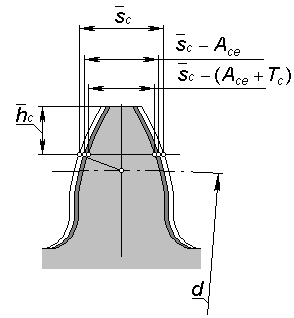
Rice. 1
To measure dimensions and  a tangential tooth meter or a special template is required, the measuring surfaces of which touch the surface of the tooth profiles.
1.2. Common normal length
The tangent line to the base circle of the gear that intersects z w of its teeth and is the normal to both extreme involutes, they are called common normal.
The distance between the opposite side surfaces of the teeth of a cylindrical gear along the common normal to these surfaces is called the length of the common normal W (fig. 2).
The length of the common normal does not depend on at what points of the tooth profiles this normal intersects two opposite involutes. The change in the length of the common normal is proportional to the change in the offset of the original contour xm gear cutting tool. It is also important that size control w not associated with any auxiliary base for installing the measuring tool.
The specified properties of the common normal show the advantage of this method of controlling the thickness of the wheel tooth. This dimension can be measured with a vernier caliper, micrometer, special limit bracket. 
Rice. 2
The length of the common normal for cylindrical wheels with external straight teeth calculated by the following formula [2]
,
where m- module, mm; a - the angle of the profile of the original contour, according to the GOST 13755-81 standard a = 20 0; z w- the number of teeth in the length of the common normal; x- displacement coefficient; z- the number of teeth of the controlled wheel; inv a - involute angle corresponding to the profile angle a, for spur gears inv
a =
tg
a -
a .
The length of the common normal for cylindrical wheels with external helical teeth calculated by a similar formula
,
where m n- normal module, mm;
 , and the end angle of the profile of the original contour
  ... Here
- the pitch angle of the tooth line specified by the drawing of the gear wheel.
... Here
- the pitch angle of the tooth line specified by the drawing of the gear wheel.
For a helical gear, the length of the common normal is measured at the main angle of inclination of the tooth line b to the end of the wheel, and the possibility of measurement is checked with a sufficient width of the toothed rim b by condition
b і w sin b ,
where sin b= sin cos.
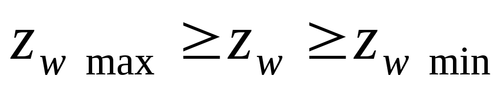
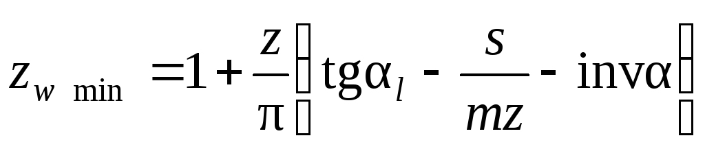
The number of teeth in the length of the common normal z w for cylindrical wheels with straight teeth must satisfy the condition  ,
,
when  ,
,  ,
,
Here a- the angle of the profile at a point on the circumference of the tops of the teeth; l- the angle of the profile at the boundary point.
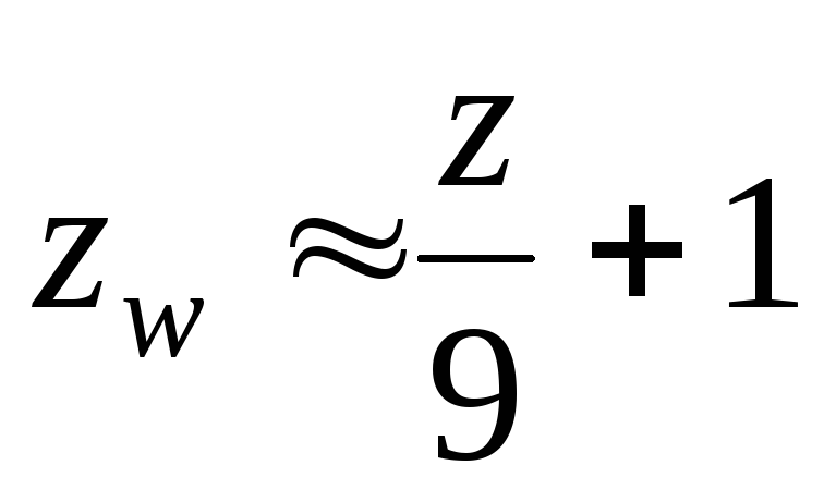
With small displacement coefficients ( x 1) to determine z w you can use a simplified formula 
with the resulting value rounded to the nearest integer value.
1.3. Dimensional tolerances for cylindrical gears
The formulas considered above for calculating the nominal measuring dimensions of the cylindrical gears guarantee the backlash-free gearing of the wheels in the transmission. In real gear drives, a guaranteed side clearance in order to eliminate jamming of the teeth during operation under load as a result of temperature deformations of the transmission parts, as well as to place a layer of lubricant on the working profiles of the teeth. The side clearance in engagement is also necessary to compensate for errors in the manufacture and installation of the gear. It is mainly determined by the value of the center distance a w transmission and thickness s wheel teeth.
The standard for involute gear cylindrical gears (GOST 1643-81) establishes eight types of lateral clearance tolerances: h, d, c, b, a, z, y, x(the designations of the tolerances are arranged in ascending order of the tolerance value). The accepted value of the guaranteed side clearance is the basis for the appointment pairing type gear wheels. The same standard provides six types of pairing: H- zero clearance, E- small clearance, C and D- reduced clearance, B- normal clearance, A- increased clearance. View mates N, E and WITH require increased precision in the manufacture of wheel teeth. They are used for reversible transmissions with high requirements for the kinematic accuracy of the transmission, as well as in the presence of torsional vibrations of the transmission shafts. Most often, in medium-sized mechanical engineering, gears with interface types are used V and WITH... In the absence of special requirements for the gear train, a certain type of lateral clearance tolerance is used with each type of mating, indicated by a lowercase letter similar to the letter of the mating type (for example, A- a, V - v, WITH - with etc.).
The tolerance field for the measuring size of the gear is always directed to the tooth body, therefore, the maximum deviations of the measuring size (upper and lower) always have negative values [1].
1.3.1. Limit deviations of the constant tooth chord. Calculation of values marginal deviations the size of a constant chord is performed in the following sequence:
- designate (or accept according to the drawing of the gear) the tolerance field of the diameter of the tops of the teeth Ad a on recommendation: with a degree of accuracy 7 - h 10, with a degree of accuracy 8 - h 11, with a degree of accuracy 9 - h 12;F r ;
According to the table. 2 determine the smallest (upper) deviation of the tooth thickness A behold ;
According to the table. 3 determine the tolerance for tooth thickness T with ;
Then the largest (lower) deviation of the tooth thickness is calculated ( A behold + T with);
In the control complex of the table of parameters of the gear rim, the value of the size of the thickness of the constant chord is recorded 
Table 1
| F r, μm |
|||||
| Accuracy degree | Module m, mm | Pitch circle diameter, mm |
|||
| St. 12 up to 50 | St. 50 up to 125 | St. 125 up to 280 | St. 280 up to 560 |
||
| 7 | 1 to 2 St. 2 to 3.55 St. 3.55 to 6 St. 6 to 10 | 30 | 38 | 48 | 63 |
| 8 | 1 to 2 St. 2 to 3.55 St. 3.55 to 6 St. 6 to 10 | 38 | 48 | 60 | 75 |
| 9 | 1 to 2 St. 2 to 3.55 St. 3.55 to 6 St. 6 to 10 | 48 | 60 | 75 | 95 |
table 2
| Pairing type | | Pitch circle diameter, mm |
|||||
| Up to 80 | St. 80 to 125 | St. 125 to 180 | St. 180 to 250 | St. 250 to 315 | Sun. 315 to 400 |
||
| Deviation A behold, μm |
|||||||
| D | 7 | 38 | 45 | 50 | 60 | 65 | 70 |
| 8 | 40 | 48 | 55 | 63 | 70 | 80 |
|
| C | 7 | 60 | 70 | 80 | 90 | 100 | 110 |
| 8 | 65 | 75 | 85 | 100 | 120 | 125 |
|
| 9 | 70 | 80 | 95 | 110 | 125 | 130 |
|
| B | 7 | 95 | 110 | 125 | 150 | 170 | 180 |
| 8 | 100 | 125 | 140 | 160 | 180 | 200 |
|
| 9 | 120 | 130 | 150 | 170 | 200 | 220 |
|
Table 3
| Tolerance, radial runout of ring gear F z, μm | Type of mating teeth |
||||
| H, E | D | C | B | A |
|
| Side clearance tolerance type |
|||||
| h | d | c | b | a |
|
| Tolerance T with, μm |
|||||
| St. 25 to 32 | 38 | 48 | 60 | 75 | 95 |
| St. 32 to 40 | 42 | 55 | 70 | 85 | 110 |
| St. 40 to 50 | 50 | 65 | 80 | 110 | 130 |
| St. 50 to 60 | 60 | 75 | 95 | 120 | 150 |
| St. 60 to 80 | 70 | 90 | 110 | 130 | 180 |
| St. 80 to 100 | 90 | 110 | 140 | 170 | 220 |
| St. 100 to 125 | 110 | 130 | 170 | 200 | 260 |
| Note. If the accepted type of lateral clearance tolerance does not correspond to the type of mating (for example, V -a), then the tolerances T with chosen depending on the type of lateral clearance tolerance. |
|||||
Limit deviation of the length of the common normal . Limit deviations of the length of the common normal are calculated in the following sequence:
 .
.According to the table. 1 determine the tolerance for the radial runout of the ring gear F r ;
According to the table. 4 determine the smallest deviation of the average length of the common normal A W me(term I) ;
According to the table. 5 determine the smallest deviation A W me(term II);
Calculate the value of the smallest (upper) deviation of the average length of the common normal A Wme as the sum of the values of the terms I and II;
According to the table. 6 determine the tolerance for the average length of the common normal T W m, depending on the radial runout tolerance of the ring gear F r(see table. 1);
Calculate the lower deviation of the size of the length of the common normal as the sum of the values of the upper deviation and the tolerance field for the length of the common normal ( A W me + T W m);
In the table of parameters of the gear rim in the drawing of the gear wheel, they are dimensioned  .
.
Table 4
| View tooth mating | Wheel pitch diameter, mm |
||||||||||||
| The degree of accuracy according to the standards of smoothness | St. 12 up to 20 | St. 20 to 32 | St. 32 to 50 | St. 50 to 80 | St. 80 to 125 | St. 125 to 180 | St. 180 to 250 | St. 250 to 315 | St. 315 to 400 |
||||
| Least deviation A W me(term I), μm |
|||||||||||||
| WITH | 3 – 6 | 50 | 50 | 50 | 50 | 60 | 70 | 80 | 90 | 95 |
|||
| V | 3 – 6 | 80 | 80 | 80 | 80 | 95 | 110 | 125 | 140 | 160 |
|||
| A | 3 – 6 | 130 | 130 | 130 | 130 | 150 | 170 | 200 | 220 | 240 |
|||
Table 5
Table 6
| Tolerances for the average length of the common normal T W m |
||||||||
| Mate type teeth | Side clearance tolerance type | Radial runout tolerances of the ring gear F r, μm |
||||||
| St. 25 to 32 | St. 32 to 40 | St. 40 to 50 | St. 50 to 60 | St. 60 to 80 | St. 80 to 100 | St. 100 to 125 |
||
| Tolerances T Wm |
||||||||
| NOT | h | 22 | 24 | 26 | 28 | 32 | 38 | 45 |
| D | d | 30 | 34 | 38 | 42 | 50 | 60 | 70 |
| C | c | 42 | 48 | 56 | 63 | 75 | 90 | 105 |
| B | b | 56 | 63 | 70 | 85 | 100 | 120 | 140 |
| A | a | 71 | 85 | 100 | 120 | 140 | 160 | 190 |
| - | z | 95 | 110 | 125 | 140 | 170 | 200 | 250 |
| - | y | 125 | 150 | 170 | 190 | 210 | 260 | 320 |
| - | x | 150 | 170 | 200 | 220 | 280 | 340 | 420 |
2. Features of calculating the measuring dimensions of the tooth of bevel spur gears
The relative position of opposite (right and left) tooth profiles of the bevel wheel determines the thickness of the tooth on the outer (additional) cone of the wheel, which depends on the displacement coefficient NS e and the coefficient of change of the estimated tooth thickness NS .
The displacement coefficients for bevel gears significantly affect the geometry and quality indicators of the gear transmission (on the contact and bending strength of the teeth, their wear resistance, etc.). The choice of rational displacement coefficients for bevel gears is one of the important milestones gear design. It is most efficient to produce it using blocking circuits [4].
In practice, in bevel gears with a gear ratio u1 gear is recommended to be made with a positive offset NS e 1, according to table. 7, and a wheel with an equal negative value ( NS e 2 = - NS e 1).
For programs that have u and z 1 differs from those indicated in table. 7, the offset coefficients are rounded up.
Table 7
| Number of gear teeth z 1 | Displacement coefficient NS e 1 at gear ratio u |
|||||||||
| 1 | 1,12 | 1,25 | 1,4 | 1,6 | 1,8 | 2 | 2,5 | 3,15 | 4 |
|
| 12 | - | - | - | - | - | - | - | 0,50 | 0,53 | 0,56 |
By installing gear cutting tools on the machine, you can change the thickness of the tooth of the cut wheel, regardless of the offset ( x e m) against the calculated one. This method is used mainly for zero gears: by weakening a stronger tooth, you can strengthen a less strong one and thereby increase the load capacity of the gear as a whole. In this way, excessive sharpening of the tooth of one of the transmission wheels is eliminated.
To select the coefficient of change in the estimated tooth thickness recommend [5] empirical formula
Direct measurement of bevel gear tooth thickness or coefficients NS and NS it is difficult, easier to use for this purpose any conveniently measured dimensions and indirectly check the thickness of the tooth using them. Such a measuring dimension for spur bevel gears is the size of a constant chord, measured by a tangential tooth meter or a special bracket (template) at the outer end of the tooth (on an additional taper).
2.2. Limit deviations of the external constant chord
The calculation of the maximum deviations of the size of the constant chord of the tooth is performed in the following sequence:
Calculate (or take from the wheel parameters table) the average pitch diameter  ;
;
- calculate the smallest deviation of the constant chord of the tooth  in the middle section of the tooth as the product of two factors: the smallest deviation for the degree of accuracy 7- N(Table 8) and the correction factor TO 1 (Table 9) for actual degree the accuracy of the controlled wheel;
Table 8
| Middle module m m, mm | Average pitch diameter d m, mm |
||||||||||
| Up to 125 | St. 125 to 400 | St. 400 |
|||||||||
| Dividing cone angle ?, deg |
|||||||||||
| Up to 20 | St. 20 to 45 | St. 45 | Up to 20 | St. 20 to 45 | St. 45 | Up to 20 | St. 20 to 45 | St. 45 |
|||
| Least deviation E sc for degree 7 - N |
|||||||||||
| 1 to 3.5 St. 3.5 to 6.3 St. 6.3 to 10 | 20 | 20 | 22 | 28 | 32 | 30 | 36 | 50 | 45 |
||
Table 9
| The degree of accuracy according to the standards of smoothness | Type of mating teeth |
|||||
| H | E | D | C | B | A |
|
| Coefficient TO 1 |
||||||
| 7 | 1 | 1,6 | 2 | 2,7 | 3,8 | 5,5 |
| 8 | - | - | 2,2 | 3 | 4,2 | 6 |
| 9 | - | - | - | 3,2 | 4,6 | 6,6 |
When measuring the thickness of the teeth at the outer end of the gear, the smallest (upper) deviation of the average constant chord of the tooth  calculated by the formula
  ,
,
where R e and R m- respectively, the outer and average bevel distance of the gear wheel;
According to the table. 10 determine the runout tolerance of the bevel gear rim F r ;
According to the table. 11 determine the tolerance for the average constant chord of the tooth  ;
;
Calculate the largest (lower) deviation of the average constant chord of the tooth ( ![]() );
);
Table 10
| Accuracy degree | Middle district module m m, mm | Average pitch diameter d m, mm |
||
| Up to 125 | St. 125 to 400 | St. 400 to 800 |
||
| Runout tolerance F r , μm |
||||
| 7 | 1 to 3.5 St. 3.5 to 6.3 St. 6.3 to 10 | 36 | 53 | 63 |
| 8 | 1 to 3.5 St. 3.5 to 6.3 St. 6.3 to 10 | 45 | 63 | 80 |
| 9 | 1 to 3.5 St. 3.5 to 6.3 St. 6.3 to 10 | 56 | 80 | 100 |
Table 11
| Side clearance tolerance type | Runout tolerance of the ring gear F r, μm |
|||||
| St. 32 up to 40 | St. 40 up to 50 | St. 50 up to 60 | St. 60 up to 80 | St. 80 up to 100 | St. 100 to 125 |
|
| Tolerance  , μm , μm |
||||||
| h a | 42 | 50 | 60 | 70 | 90 | 110 |
In the table of parameters of the gear rim on the drawing of the bevel gear, the size of the constant chord of the tooth is written in shape  .
.
Bibliography
Tolerances and landings. Directory. In 2 hours, Part 2 / Ed. V.D. Myagkova. 5th ed., Rev. and add. - L .: Mechanical engineering, 1978 .-- S. 545 - 1032.
Handbook on geometric calculation of involute gear and worm gears / Ed. I.A. Bolotovsky. - 2nd ed., Rev. and add. - M .: Mashinostroenie, 1986 .-- 448 p.
Tarabasov N.D., Uchaev P.N. Design of parts and assemblies of machine-building structures: Handbook. - M .: Mechanical Engineering, 1983 .-- 239 p.
Straight bevel gears: Handbook / I.A. Bolotovsky, B.I. Guryev, V.E. Smirnov, B.I. Shenderei. - M .: Mashinostroenie, 1981 .-- 104 p.
Gears, bevel gears with straight teeth. Geometry calculation. GOST 19624-74.
DIMENSIONS OF GEAR WHEELS
INSTRUCTIONS
To course design on machine parts
And the basics of design
Editor Sokolova O.A.
Signed for print on 05.12.2004. Format 60x84 1/16
Offset paper. Printing is flat. Typeface Times New Roman Cyr.
CONV. print l. CONV. cr. - Ott. Uch. - ed. L.
Circulation of copies Order no.
USATU Editorial and Publishing Complex
450000, Ufa center, st. K. Marx, 12
The tangent line to the base circle of the gear that intersects z w of its teeth and is the normal to both extreme involutes, they are called common normal.
The distance between the opposite side surfaces of the teeth of a cylindrical gear along the common normal to these surfaces is called the length of the common normal W (fig. 2).
The length of the common normal does not depend on at what points of the tooth profiles this normal intersects two opposite involutes. The change in the length of the common normal is proportional to the change in the offset of the original contour xm gear cutting tool. It is also important that size control w not associated with any auxiliary base for installing the measuring tool.
The specified properties of the common normal show the advantage of this method of controlling the thickness of the wheel tooth. This dimension can be measured with a vernier caliper, micrometer, special limit bracket.
The length of the common normal for cylindrical wheels with external straight teeth calculated by the following formula [2]
where m- module, mm; a - the angle of the profile of the original contour, according to the GOST 13755-81 standard a = 20 0; z w- the number of teeth in the length of the common normal; x- displacement coefficient; z- the number of teeth of the controlled wheel; inv a - involute angle corresponding to the profile angle a, for spur gears inv a = tg a - a .
The length of the common normal for cylindrical wheels with external helical teeth calculated by a similar formula
where m n- normal module, mm;
 , and the end angle of the profile of the original contour
 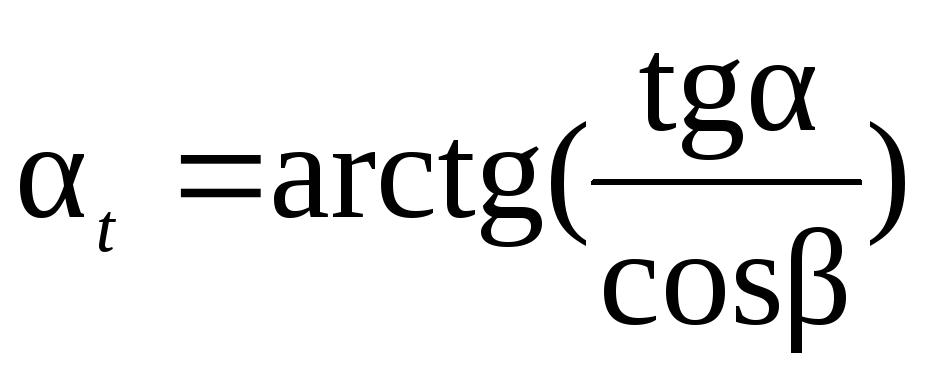 ... Here
- the pitch angle of the tooth line specified by the drawing of the gear wheel.
... Here
- the pitch angle of the tooth line specified by the drawing of the gear wheel.
For a helical gear, the length of the common normal is measured at the main angle of inclination of the tooth line b to the end of the wheel, and the possibility of measurement is checked with a sufficient width of the toothed rim b by condition
b ³ w sin b ,
where sin b= sin cos.
The number of teeth in the length of the common normal z w for cylindrical wheels with straight teeth must satisfy the condition
 ,
,
when 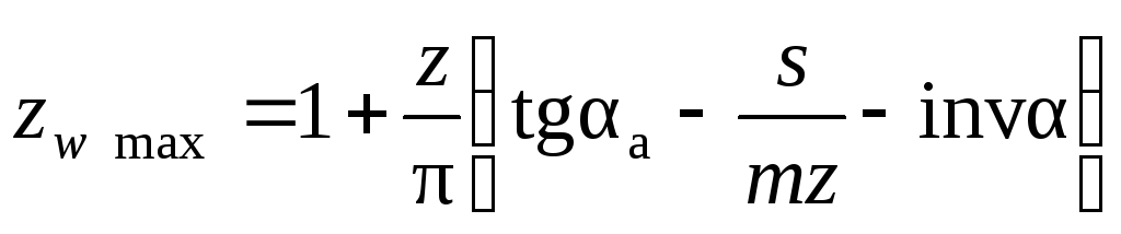 ,
,

 ,
,
Here a- the angle of the profile at a point on the circumference of the tops of the teeth; l- the angle of the profile at the boundary point.
With small displacement coefficients ( x 1) to determine z w you can use a simplified formula
with the resulting value rounded to the nearest integer value.
1.3. Dimensional tolerances for cylindrical gears
The formulas considered above for calculating the nominal measuring dimensions of the cylindrical gears guarantee the backlash-free gearing of the wheels in the transmission. In real gear drives, a guaranteed side clearance in order to eliminate jamming of the teeth during operation under load as a result of temperature deformations of the transmission parts, as well as to place a layer of lubricant on the working profiles of the teeth. The side clearance in engagement is also necessary to compensate for errors in the manufacture and installation of the gear. It is mainly determined by the value of the center distance a w transmission and thickness s wheel teeth.
The standard for involute gear cylindrical gears (GOST 1643-81) establishes eight types of lateral clearance tolerances: h, d, c, b, a, z, y, x(the designations of the tolerances are arranged in ascending order of the tolerance value). The accepted value of the guaranteed side clearance is the basis for the appointment pairing type gear wheels. The same standard provides six types of pairing: H- zero clearance, E- small clearance, C and D- reduced clearance, B- normal clearance, A- increased clearance. View mates N, E and WITH require increased precision in the manufacture of wheel teeth. They are used for reversible transmissions with high requirements for the kinematic accuracy of the transmission, as well as in the presence of torsional vibrations of the transmission shafts. Most often, in medium-sized mechanical engineering, gears with interface types are used V and WITH... In the absence of special requirements for the gear train, a certain type of lateral clearance tolerance is used with each type of mating, indicated by a lowercase letter similar to the letter of the mating type (for example, A- a, V - v, WITH - with etc.).
The tolerance field for the measuring size of the gear is always directed to the tooth body, therefore, the maximum deviations of the measuring size (upper and lower) always have negative values [1].