The car's transmission performs an important function - it transfers the rotation of the crankshaft to the wheels.
The main elements of the transmission:
- clutch - we talked about it on the site, it connects and disconnects the gearbox and the crankshaft flywheel;
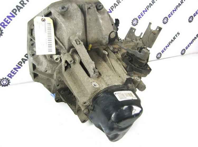
- gearbox - allows you to transform uniform rotation into a specific driving mode;
- cardan or cardan gear - used on cars with rear or four-wheel drive, serves to transfer the moment of movement to the driving axle;
- differential - distributes the moment of movement between the driving wheels;
- gearbox - for increasing or decreasing, provides a constant angular velocity.
If we take an ordinary mechanical box gears, we will see three shafts in its composition:
- primary or leading - connects the gearbox to the flywheel through the clutch;
- secondary - rigidly connected to the cardan, it is he who is designed to transfer the torque to the cardan, and from it to the drive wheels;
- intermediate - transfers rotation from input shaft secondary.
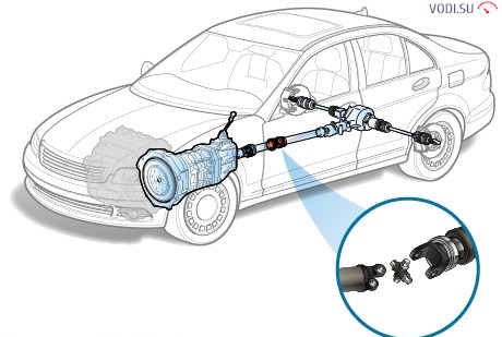
The purpose of the cardan transmission
Any driver who has driven RWD or four-wheel drive car, and even more so at the GAZon or ZIL-130, I saw a driveshaft - a long hollow tube, consisting of two segments - a longer and a shorter one, they are connected to each other by an intermediate support and a cross, forming a hinge. At the front and rear of the propeller shaft, flanges can be seen for rigid connection to the rear axle and the output shaft exiting the gearbox.
The main task of the cardan is not only to transfer rotation from the gearbox to the gearbox of the rear axle, but also to ensure that this work is transmitted with variable coaxiality of the articulated units, or, in simple articulate language, a rigid connection of the driving wheels with the secondary shaft of the gearbox is provided while not interfering with the independent movement of the wheels and suspension relative to the body.
Also, the device of the car is such, especially when it comes to trucks, that the box is located higher in relation to the surface than the rear axle gearbox. Accordingly, it is necessary to transfer the moment of movement at a certain angle, and thanks to the gimbal joint device, this is quite possible. Moreover, in the process of driving, the car's frame may deform slightly - literally by millimeters, but the cardan device makes it possible to ignore these minor changes.

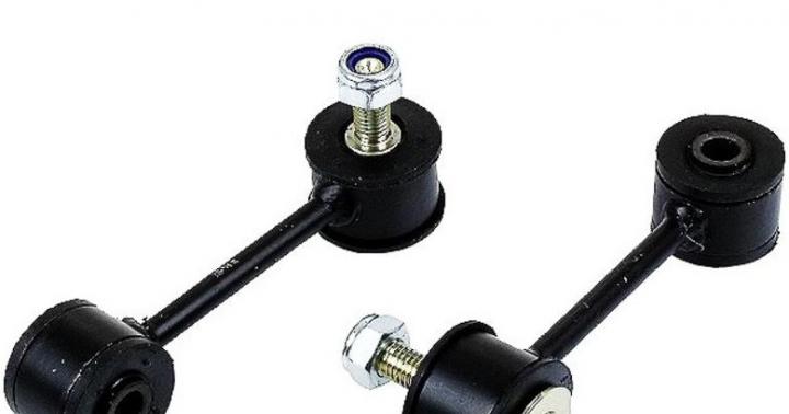
It should also be said that the cardan drive is used not only in all-wheel and rear-wheel drive vehicles, but also on front-wheel drive vehicles. True, here it is called differently - SHRUS - joints of equal angular velocities. CV joints connect the gearbox differential to the front wheel hubs.
Generally speaking, the cardan transmission principle is used for other purposes as well:
- lower and upper steering gimbals;
- for communication junction box with a drive axle gearbox - on off-road vehicles with a plug-in all-wheel drive, type;
- for engine power take-off - the power take-off shaft coming from the gearbox of tractors is used to drive various agricultural equipment through the cardan, for example, potato diggers or planters, disc harrows, seeders and so on.
Device
As already mentioned above, the cardan shaft consists of two hollow pipes articulated by means of a hinge joint. In the front part there is a spline roller that meshes with the gearbox output shaft by means of an adapter clutch.
At the junction of the two parts of the cardan, each of them has a fork, and they are connected to each other using a cross. There is a needle bearing at each end of the cross. Forks are put on these bearings and thanks to them the transmission of rotation is possible from one shaft to another when an angle is formed from 15 to 35 degrees, depending on the device. Well, in the rear part, the cardan is screwed to the gearbox using a flange, which is attached with four bolts.
![]()
An important role is played by the intermediate support, inside which there is a ball bearing. The support is screwed to the underside of the car, and the bearing allows the shaft to rotate freely.
As we can see, the device is quite simple, based on the hinge principle. However, engineers need to make accurate calculations to ensure that all suspension components work in a balanced and consistent manner.
Cardan drive car is called a mechanism that transfers torque between shafts that intersect in the central part of the cardan drive of the car and are distinguished by the possibility of mutual angular movement. It is actively used in various spheres of human activity in cases where the alignment of rotating elements is very difficult to ensure. A gear clutch can also perform similar functions.
As a rule, the cardan transmission of a car is used in an automobile transmission mission, as well as in steering.
Cardan transmission vehicle can provide the connection with the following transmission elements:
- Power unit and gearbox;
- Gearbox and transfer case;
- Gearbox and main gear;
- Main gear and transfer case;
- Driving wheels and differential.
Cardan shaft in the car, it is designed to transmit torque from the gearbox to the drive axles in the case of an all-wheel drive or classic layout. Also used in the crash-proof steering column to connect the steering actuator me-ha-niz-ma and the steering shaft.
The cardan transmission of the car has one significant drawback - the non-synchronization of the gross rotations (one of the shafts has uniform rotation, the other does not). The rotations begin to increase if the angle between them increases. This excludes the possibility of using the cardan transmission of the car in some devices, for example, in the transmission of cars with front-wheel drive (where the main problem is the transmission of torque to the swivel car wheels). By and large, this drawback can be compensated for by using paired joints on one shaft, which are in a position rotated by a quarter of a turn relative to each other. However, where synchronization is required, as a rule, CV joint (constant velocity joint) is used - a more complex, but more perfect design for a similar purpose.
According to their layout, the cardan drives of the car are divided into closed and open.
Closed variant of the cardan transmission of the car is located inside the tube, which, in turn, can be perceived by a component of the vehicle's suspension. In the cardan transmission of this type of car, only one joint is used, and the uneven rotation of the cardan shaft is compensated by its elasticity. There are designs where the function of the propeller shaft is performed by a torsion bar (a small elastic shaft); cardan joints are missing here.
Open variant of the cardan transmission of the car does not have a pipe, but the reactive moment is perceived jet thrust or springs. The cardan transmission of the car must include at least two hinges, as well as a compensating link, since the distance between the connected units changes during movement. On cars with a long wheelbase, the cardan transmission of the car is used, which consists of two shafts. This eliminates the possibility of coincidence of the maximum angular velocity of the shaft with the acceptable one. Reducing the length of the shaft increases its critical rotational speed, which should be at least 1.5 times higher than the maximum possible during operation. The design of a cardan transmission of a car equipped with two shafts requires the use of an intermediate support of one of the two shafts, the bearing of which is mounted on the body (see the body of a car) or a frame in an elastic ring to compensate for the axial movement of the engine (see the device of the car engine).
Types of cardan gears
Let's consider the main types of cardan drives.
Cardan drives of single-shaft type used on short-wheelbase cars, which differ in the 4x2 wheel shape, the cardan transmission connects the gearbox to the rear driving axle. This type cardan transmission includes a cardan shaft, as well as two cardan joints.
Cardan transmission of two-shaft type used on trucks and buses, as well as on cars with an extended wheelbase, the wheel shape of which is 4x2. A cardan transmission of a two-shaft type connects the rear axle with the gearbox. This type of cardan transmission consists of three cardan joints, two cardan shafts, intermediate support.
In cars with 6x6 wheel shape and equipped with individual drive leading bridges, the connection of the rear drive axle with the transfer case is carried out by means of a double-shaft cardan transmission with an intermediate support. The connection of the front and middle drive axles with the transfer case is carried out using cardan drives of a single-shaft type.
There are cars with the shape of 6x6 wheels, but their middle axle is through passage, the connection between the gearbox and the transfer case, and the transfer case, along with this with the drive axles, is performed by cardan transmissions of a single-shaft type. An additional gearbox transfers torque to the driving rear axle.
The types of cardan transmissions considered above are the main ones in av-to-mo-bi-le-stro-e-nii.
The next important point on which we need to stop is the cardan transmission device. The propeller shaft is designed to transmit torque from the vehicle's gearbox or transfer case to the vehicle's drive axle. Its specific differences from ordinary shafts are the ability to change its length and the transmission of torque at a varying angle. What is this?
The cardan drive device is shown in the figure below. A rear-wheel drive vehicle option is selected here.

Any axle of the machine is connected to the frame through a suspension with springs. As a result, when driving on an uneven road, the wheels with bridges seem to bounce, and the car frame itself, due to the work of the springs, remains practically at the same level from the ground. Accordingly, when you change the position of even one wheel (for example, a pit), the distance from it to the gearbox and the skew angle relative to the horizon change. To compensate for these phenomena, they came up with a cardan transmission of the car.
The propeller shaft looks like a pipe assembled from two half-shafts connected by splines. One shaft has a slot outward, the other inward. Along the splines, these half shafts can move relative to each other, while not losing torque. Due to this, the length of the entire propeller shaft changes. There are cardan joints at the ends of both shafts. The hinge itself consists of two movable forks connected to the crosspiece through bearings. The ends of the forks are also fixed through bearings at both ends of the propeller shaft. Such a movable connection allows the transfer of torque at a varying angle. All this together and forms the cardan transmission of the car.
Constant Velocity Joint (CV joint)
We have considered the simplest variant of the cardan transmission of the car. But in the case of a front-wheel drive car, this whole structure is complicated and new elements are added. Since the front wheels are also steerable, the angles of inclination and turning become even larger and a simple propeller shaft will not help here in any way. In addition, in front-wheel drive vehicles, the gearbox is combined with the front axle or both of these mechanisms are located next to each other. Therefore, the most successful technical solution for such cars was the use of constant velocity joints (CV joints).
The simplest version of the constant velocity joint is shown in the figure below.

For a complete understanding, you can give an example of any ballpoint pen. At the end of its rod, there is a groove in the metal cone where a small ball is placed. It is its ideal shape that allows you to tilt the pen at different angles when writing and draw with it in different directions. Now imagine that there are several balls in the pen and all of them must touch the sheet of paper at the same time. Approximately the same design for a hinge of equal angular velocities. At the end of the driven shaft of the gearbox there is an "asterisk" with grooves along which the balls can move along the axis of the shaft. From the outside, the balls are wrapped around the body of the constant velocity joint with the same grooves. Thus, the balls form a kind of vertical circle parallel to the wheel.
Now the very process of work of the hinge of equal angular velocities. Torque from the driven shaft of the car's gearbox through the balls to the hinge housing, and from it to the wheel. In this case, these balls play the role of splines. Imagine that the wheel does not spin, but begins to turn to the left. In this case, its front part turns to the left, and its rear part to the right, since the center of the wheel is fixed on the hinge. Then the balls begin to move along the grooves, like the wheel. That is, diametrically located balls are displaced in opposite directions: front - to the left, rear by the same distance to the right. Well, in motion, the balls are constantly spinning and changing their position depending on the position of the wheel. In this case, the torque is transmitted constantly, and the speeds of rotation of the shaft and wheel at any angle are always the same. Hence the name - constant velocity joint. Such a mechanism is very "afraid" of dirt and external mechanical stress, since the balls stop sliding along the grooves. Therefore, constant velocity joints are always protected by a strong cover and lubricated inside with grease.
Propeller drive malfunctions
Consider the main malfunctions of the driveline.
The main signs of cardan transmission malfunctions are jerks and knocks during starting and shifting, noise and vibration. Enough strong vibrations The driveline can be felt at certain vehicle speeds when noise and vibration levels can reach peak levels. The car shudders and a hum is heard. It is strictly forbidden to operate a vehicle with cardan transmission malfunctions.
Propeller shaft malfunctions consist in loosening the bolts of the cardan flanges, wear of the cardan components, wear of the bearings from the spline connection. These malfunctions of the driveline must be eliminated, as it is very dangerous for the movement of the vehicle.
If you feel any malfunctions of the cardan transmission while driving, you need to stop the car, carefully check everything and, if necessary, tighten the bolts of the flange yoke to the flange of the drive gear of the rear axle, the bolts of the elastic coupling to the flange of the gearbox output shaft, as well as the connection bolts elastic intermediate support. In the process of checking the malfunction of the cardan gear, you should make sure that there is no increased runout of the drive gear flange, the rear gear, various seizures in the splined joints, and backlash in the cardan. If during the check it turns out that the runout of the flange exceeds 0.15 mm, then it is necessary to remove the flange from the gears, turn it 180 ° and reinstall it. If the runout cannot be eliminated with this, then it is recommended to replace or straighten the flange. The presence of backlash in the cardan can be checked by pushing it up. If there is a play in the cardan bearings, it is necessary to replace the bearing and the crosspiece. When installing the bearings, make sure that all the needles are in the cup. The absence of even one needle will lead to the destruction of the bearing due to the misalignment of the needles.
Operation of the cardan transmission of the car
For front-wheel drive and rear-wheel drive vehicles, in cardan gears the main problem are the hinges. Shafts and pipes rarely need to be changed unless you are jumping into a rocky pit twice a day. And the hinges will last a very long time if you prefer a quiet ride. Any car needs to be driven in a measured and smooth manner, besides, front-wheel drive cars require very careful driving, because if the special protective covers of the constant velocity joints are damaged, dirt penetrates into them, and they instantly fail. The condition of these covers should be checked, if cracks and ruptures appear, they must be instantly replaced with new ones. When the bearings or crosspieces are worn, a clicking sound can be heard when shifting gears and starting off. For shafts with ball joints, these clicks also occur when the front wheelset is turned at maximum angles.
When wear on the propeller shaft center bearing of a rear-wheel drive vehicle reaches a certain limit, noticeable noise is generated in the underbody area and unpleasant vibration is felt.
If the car is operated normally, the ball joints of the front shafts and the joints of the propeller shaft will last for a very long time, they will last for 100,000 km. mileage. And the shafts and pipes, in principle, should not be changed at all; if it so happened that the shaft with ball joints is deformed or one of the driveshafts is bent, then it makes sense to replace the faulty assemblies.
The operating time of the ball joints and propeller shaft joints is reduced by: incorrect choice of speed, as well as gears on poor road surfaces, sharp accelerations and starts, driving on snow and deep rut, slipping in mud.
The above malfunctions of the cardan transmission and the rules for its operation are the most basic.
The cardan drive is used to transfer torque between units, the axes of the shafts of which do not lie on one straight line and can change their relative position.
In all-wheel drive wheeled vehicles, the cardan drive usually connects the driven shaft of the gearbox to the drive shaft of the transfer case, and the driven shafts of the transfer case - to the drive shafts of the main gears of the driving axles. Units fixed to the frame (in particular, the gearbox and transfer case), can move relative to each other as a result of deformation of their supports and the frame itself, and the drive axles are attached to the frame through the suspension, therefore they can move relative to the frame and the units attached to it when the elastic suspension elements are deformed. In this case, not only the angles of inclination of the cardan shafts connecting the units can change, but also the distance between the units.
Rice. Cardan transmission diagram:
1, 4, 6 - cardan shafts; 2, 5 - cardan joints; 3 - compensating connection; y1, y2 - angles between the shafts
In general, the cardan drive consists of cardan joints 2 and 5, cardan shafts 1.4 and 6 and an expansion joint 3. Sometimes the cardan shaft is installed on an intermediate support attached to the vehicle frame cross member.
Cardan joints provide the transfer of torque between shafts, the axes of which intersect at an angle. There are cardan joints of unequal and equal angular velocities. Universal joints of unequal angular velocities are divided into elastic and rigid. By design, universal joints of equal angular velocities are ball with dividing grooves, ball with a dividing lever and cam. Usually they are installed in the drive of the driven steered wheels, where the angle between the shafts can reach 45 °, and the center of the universal joint must coincide with the point of intersection of the axes of rotation of the wheel and its rotation.
Elastic universal joints transfer torque between shafts with axes intersecting at an angle of 2 ... 3 ° as a result of elastic deformation of the connecting elements.
A rigid universal joint of unequal angular velocities transfers torque from one shaft to another due to the movable connection of rigid parts. It consists of two forks - 3 and 5, in the cylindrical holes of which the ends A, B, C and D of the connecting element - crosspieces are installed on bearings 4. The forks are rigidly connected to shafts 1 and 2. Fork 5 can be rotated about the axis of the crosspiece BG and into at the same time, together with the crosspiece, to rotate about the AB axis, due to which it is possible to transfer rotation from one shaft to another with a varying angle between them.

Rice. Diagram of a rigid universal joint of unequal angular velocities
If the shaft 7 rotates around its axis at an angle a, then the shaft 2 during the same time will rotate through the angle B. The ratio between the angles of rotation of the shafts 7 and 2 is determined by the expression tga = tgВ * cozy, where y is the angle at which the axes of the shafts are located. From this expression it follows that the angle B is either less than the angle a, then equal to it. The equality of these angles occurs every 90 ° of rotation of the shaft 7. Thus, with a uniform rotation of the shaft 1, the angular speed of the shaft 2 is uneven and changes sinusoidally. The uneven rotation of the shaft 2 will be the more significant, the greater the angle y between the axes of the shafts. If the uneven rotation of shaft 2 is transmitted to the shafts of the units, additional pulsating loads will arise in the transmission, increasing with an increase in the angle y. So that the uneven rotation of shaft 2 is not transmitted to the shafts of the units, two cardan joints are used in the cardan transmission. They are installed so that the angles y1 and y2 are equal; the forks of the universal joints, fixed on the unevenly rotating shaft 4, must be located in the same plane. The uniformity of rotation of the driven shaft can also be achieved by using a universal joint of equal angular velocities.
The principle of operation of the universal joint of equal angular velocities is explained by the diagram shown in the figure. Lever 2 is connected to the drive shaft 7, and lever 3 is connected to the driven shaft 4. Levers 2 and 3, when the shafts rotate, constantly contact at point A, the linear speed of which is the same for both levers, i.e., v = = w1B = w2a = wа ... The equality of the angular velocities w2 and w2 is possible if a = b. This condition is satisfied if the angle 0 is equal to the angle W and the point A of contact of the levers lies on the bisector of the angle between the shafts 7 and 4. When the shafts rotate, point A must be in the bisector plane. Structurally, this condition can be provided different ways... The most widespread are ball-type universal joints of equal angular velocities. Other types of constant velocity joints are also used.

Rice. The scheme of the universal joint of equal angular velocities
The driveshaft is a design that is included in the structure of the transmission of rear-wheel drive and all-wheel drive cars, since such cars need to supply torque (rotation) from the engine to the rear and front axles... It is this function that this device performs through the operation of the checkpoint.
Cardan shaft mechanism
Fundamental details:
- outboard bearing;
- double hinge;
- sliding fork;
- various intermediate seals (oil seals, gaskets);
- various fastening devices.
According to its technology, it is a thin-walled hollow pipe, with a fixed hinge fork installed on it on one side and a movable fork and a splined joint on the other. Regarding which model of car and what type of gearbox is on it, the cardan shaft can be from 2 or 3 sections (front cardan, intermediate cardan and rear universal joint). A single-section shaft contains a central part and 2 tips with crosses at the ends.
The mechanism simultaneously appears as a support for other elements of the car.
Depending on the model of the machine, its dimensions, features, the cardan structure has a different mass and design. Small gimbals are made solid and solid, which enhances their intermediate role.
The manufacture of universal joint shafts is usually based on steel. This material allows you to achieve minimum weight and dimensions with maximum functionality.
Parts of the gimbal
The operability of the device is ensured by hinges, which are based on crosspieces. The crosses provide the ability to rotate for 2 mating shafts, the angles of which change relative to each other. The greatest efficiency occurs when the rotation angle reaches 0 ° -20 °. If the angle is greater, the crosspiece is subjected to strong overloads. And also the shaft loses balance, and vibrations are felt.
Another important component is the sliding splined joint of the propeller shaft. The principle of its work is as follows. The gearbox, connected to one end of the shaft, is tightly fixed in the inner region of the car body, and the axle gearbox, connected to the other side of the shaft, is connected to the suspension. When crossing unevenness, the gap between the transmission and the axle reduction gear is lengthened. As a result, the shaft must be stretched (including the front universal joint and the rear universal joint). And the splined connection with the gland in the form of a seal guarantees safe stretching of the device.
The system also has a propeller shaft outboard bearing. He has the duty of an auxiliary support for the 1st of the shaft components (for example, the rear universal joint). A bearing bracket, sealed with an oil seal and lubricated with grease, attaches to the body and holds the part (for example, the rear universal joint), preventing it from rotating. The number of bearings is equal to the number of elements that make up the shaft.
The length of the shaft plays a special role in rotation.
If the design consists of 2 halves, then the front is the intermediate cardan, and the second is the rear cardan. And if it consists of 3, then the first is the front cardan, the middle is the intermediate cardan, and the final is the rear cardan. These elements are connected with an intermediate support and are fixed to the car body by it.
During operation, the length of the shaft may change. For this, a splined connection with a sealing gland and special grease is installed on it.
Cardan transmission with hinges of equal angular velocities
The technology of transmission in cars with hinges of the same angular velocity often finds application in cars with front-wheel drive. This circuit is necessary to connect the differential to the wheel drive. This design has 2 identical joints, lubricated with grease, to which the front propeller shaft is connected, transmitting rotation. The joint closest to the shaft is called internal, and the opposite joint is called external. The front universal joint, having the required amount of lubrication, provides a reduction in noise levels regardless of the type and size of the joint.
This mechanism can also be used in cars with rear wheel drive.
Advantages
- Resistant to heavy loads. Some vehicles(for example, limousines, Belazes and other heavy vehicles), a particularly reliable transmission of rotation to rear axle... After all, the leading rear wheels in such cars, this is a very important aspect.
- Repair availability. Due to the various components, in the event of a particular breakdown, only one specific spare part can be replaced. It is not necessary to completely replace the entire mechanism assembly. It is not that expensive and the replacement process is the easiest.
disadvantages
- Dimensions and weight of the cardan mechanism. The larger and heavier the car, the larger the gimbal will be in size and weight. Accordingly, the total weight of the car increases, and, in addition, it is necessary to reduce the dimensions of the cabin.
- Extraneous vibrations. An additional unit, which may have a propeller shaft, despite the lubrication and strong fixation, will somehow create a kind of vibration felt both by the driver through the gearbox and by the passengers in the vehicle interior.
Workability disorders
- The main violation in the operation of the cardan structure is imbalance. This problem occurs as a result of non-compliance with the norms and incorrect fixing of the gaps in the crosses during the installation of the mechanism. Manufacturers themselves often do not follow the correct fixing of the gaps. First, an imbalance appears, which manifests itself in the form of vibration transmitted to the ball and felt when shifting gears on the gear lever. Then, the process of rapid wear of parts of the structure, including the ball one, begins. As a result, the likelihood of the vehicle losing its balance and the occurrence of a serious accident increases. Therefore, you should not neglect the rules, you should timely inspect and, if necessary, repair worn out parts.
- The appearance of a knock in the parts of the gearbox at the time of the start of driving, with a rapid increase in speed or a gear change. This can happen when:
- reducing the strength of the connections on the threads of the fasteners of the flanges and the connecting coupling of the cardan drive;
- the presence of excessive clearance in the spline or in the bearings of the crosspiece. More attention should be paid to the crosspiece, its gland and the presence of grease, since it is the cross that can become the main source of grinding, requires more frequent replacement- every 10,000 km. Less often than a cross, but still often, the outboard bearing and its oil seal deteriorate or a gap appears in the cardan joint;
- cutting of splines. It happens this way: the chain in the distributor begins to stretch and a backlash is formed. Due to the backlash, the chain jumps over the teeth by the gear of the transfer case, which at different speeds creates powerful shock loads on the splines of the front universal joint and transfer case. With such a malfunction, loud metal noises are heard from under the car. Even on original part with a mileage of 250,000 km, there is a high probability that the splines will shear and the shaft will not have a full entrance to the transfer case. Because at the time of contraction and stretching of the car body while driving, the cardan shaft either goes deep into the transfer case, then comes out of the transfer case. In principle, you can get rid of this problem for a couple of years by replacing the old universal joint with a new one, but with a spline connection of a longer length. However, the main reason is the stretched distribution chain. Therefore, it is recommended to replace the gimbal together with the chain. And if necessary, it is important to take into account all the characteristics of the flange on the distributor (dimensions and number of spline connections, outer diameter and diameter in depth of the splines).

Strong rattling and vibrations of the car while driving can also occur due to:
- unacceptable bending of shafts;
- incorrect fixation and non-compliance with assembly marks;
- failure of the central sleeve of the intermediate coupling flange or the secondary transmission shaft ring;
- breakage of the cardan suspension support;
- weak connection of the transverse support on the thread;
- excessive clearance in the needle bearings of the crosspiece;
- loosening the connecting nut of the transmission fork;
- lack of lubrication in the splines.
Grease leakage occurs due to the destruction of the spline seal or the seal of the bearings of the box crosspieces.
Conclusion
Cardan mechanism - in other words, the pipe leading from the gearbox to the rear differential, which further distributes the rotation load to each wheel.

In the event of vibration or rattling while driving, it is imperative and urgent to inspect and repair the failed cardan elements. In addition to the fact that one of the characteristics of the cardan is the maintainability of auto parts, its timely repair will secure the further operation of the vehicle.
The transmission of an all-wheel drive wheeled vehicle includes several cardan drives with cardan joints of unequal angular speeds, as well as cardan gears with cardan joints of equal angular speeds, which are installed in the drive of the steered driving wheels.
Consider the structure of the main parts of cardan transmissions. The universal joint of unequal angular velocities consists of two forks - 1 and connected by a cross 3. One of the forks sometimes has a flange, and the other is welded to the driveshaft tube or has a splined tip 6 (or bushing) for connecting to the driveshaft. The cross pins are installed in the lugs of both forks on needle bearings 7. Each bearing is placed in the housing 2 and is held in the fork lug by a cover, which is attached to the fork by two bolts, locking washer tendrils. In some cases, the bearings are secured in the forks with retaining rings. A rubber self-tightening gland is provided to keep the grease in the bearing and protect it from water and dirt. The inner cavity of the crosspiece is filled with grease through the grease fitting, which flows to the bearings. The crosspiece usually has a relief valve to protect the oil seal from damage caused by the pressure of lubricant pumped into the crosspiece. The spline joint 6 is lubricated with an oiler 5.
The maximum angle between the axes of shafts connected by cardan joints of unequal angular velocities usually does not exceed 20 °, since at large angles it significantly decreases
Rice. Details of the universal joint of unequal angular velocities
Efficiency of cardan transmissions. If the angle between the axes of the shafts changes within 0 ... 2%, then the spikes of the cross are deformed by the needles of the bearings, and the cardan joint is quickly destroyed.
In transmissions of high-speed tracked vehicles, cardan drives with cardan joints such as gear couplings are often used, allowing the transfer of torque between shafts, the axes of which intersect at an angle of up to 1.5 ... 2 °.
Cardan shafts are usually tubular, for which special steel seamless or welded pipes are used. Forks of universal joints, splined bushings or tips are welded to the pipes. To reduce the lateral loads acting on the cardan shaft, it is dynamically balanced with cardan joints. The imbalance is eliminated by welding balancing plates to the cardan shaft, and sometimes by installing balancing plates under the cardan joint bearing caps. The relative position of the spline joint parts after assembly and balancing of the cardan transmission at the factory is usually marked with special marks.
The compensating joint of the cardan drive is usually made in the form of a spline connection that allows axial movement of the parts of the cardan drive and consists of a spline tip that enters the spline sleeve of the cardan drive. The grease is introduced into the spline connection from the grease nipple or, during assembly, the grease is put in, which is replaced after a long run of the vehicle. To protect the splined joint from leakage of grease and contamination, an oil seal and a cover are usually installed.
With a long length of cardan shafts, intermediate bearings are usually used in cardan drives. The intermediate support, as a rule, is a bracket bolted to the frame cross member, in which a ball bearing is installed in a rubber elastic ring, closed on both sides by caps with oil seals and a device for lubricating it. The presence of an elastic rubber ring makes it possible to compensate for assembly inaccuracies and bearing misalignments, which are possible due to deformations of the vehicle frame.
The ball-type universal joint of equal angular velocities with pitch grooves consists of two forks, five balls, a pin and a locking pin. The driving fork is made as a whole with the half-axle 6, and the driven fork is made with the drive shaft 23 of the wheel. Each fork 3 and 4 (Fig. A) has four grooves, four leading (side) balls 7 are installed in them, through which rotation is transmitted from one fork to another. At any angle between the shafts, the lateral balls in the grooves of the forks are in a plane dividing this angle in half, due to which the rotation from the drive shaft to the driven shaft is transmitted uniformly. The central (fifth) ball 2 is placed between the ends of the forks and ensures their centering. To be able to install the driving balls in the grooves of the forks, the central ball has a flat with a hole, with which it is installed against the inserted side ball when assembling the cardan joint. After assembling the cardan joint, the central ball is fixed in a certain position by a pin 6, which is fixed by a locking pin 5 in the hole of the driven fork.

Rice. Details of universal joints of constant angular velocities:
a - ball; b - cam; 1 - leading (side) balls; 2 - central ball; 3, 4, 7, 11 - forks; 5 - hairpin; 6 - pin; 8, 10 - cams; 9 - disk
Cardan joints of this design can operate at angles between shafts up to 30 ... 35 °. Their disadvantages are the need for accurate fixation of the shafts in the axial direction, as well as high pressures on contact surfaces, which reduces their durability and limits the use of such cardan joints on all-wheel drive wheeled vehicles with a large load capacity. Ball-type cardan joints of equal angular velocities with a dividing lever or cam, as well as double cardan joints of unequal angular velocities, are installed on them in the drive of the controlled driving wheels.
Figure b shows the device of the cam cardan joint of equal angular velocities, installed in the drive of the controlled driving wheels of KamAZ, Ural, etc. vehicles.
In the forks 7 and 11, connected with the shafts (semi-axles) of the wheel drive, the cams 8 and 10 can be rotated, which are pivotally connected to each other by a disk 9 entering their cutouts (grooves). When transmitting rotation, when the drive shafts are located at an angle (rotation of the steered wheels), each of the cams 8 and 10 rotates simultaneously relative to the fork and the disc rack. The axes of the holes of the forks lie in the same plane and coincide with the median plane of the disc 9. These axes are located at equal distances from the point of intersection of the axes of the shafts and are always perpendicular to the shafts, so the point of their intersection at any position of the forks is located in the bisector plane. The shaft of the inner fork is 11 splines connected to the axle gear of the differential, and the shaft of the outer fork 7 is connected to the wheel hub.
Cam cardan joints can operate at angles of rotation up to 50 °. Due to the large contact surface of the parts through which the forces are transmitted, the cam universal joint is small. Their main disadvantage is that efficiency is lower than that of universal joints and, as a consequence, strong heating during operation.
Cardan shafts and forks are made of carbon steel, and the crosses are made of chromium and chrome-nickel steel. For lubrication of cardan gears, transmission oil(nigrol).