How to repair the pressure regulator brake system fret 2113, stages of disassembly, detailed instructions to replace parts of the regulator VAZ 2113, VAZ 2115, VAZ 2114.
The device of the brake pressure regulator The device of the brake pressure regulator VAZ 2114, VAZ 2115, VAZ 2113 repair of the brake system brake pressure regulator, device
The device of the brake pressure regulator VAZ 2114, VAZ 2115, VAZ 2113, Lada Samara 2
Regulates the pressure in hydraulic drive brake mechanisms of the rear wheels, depending on the load on the rear axle of the car VAZ 2113, VAZ 2114, VAZ 2115. It is included in both circuits of the brake system and through it the brake fluid is supplied to both rear brake mechanisms.
In the next step, the piston presses against the brake fluid filling the system. The brake fluid redistributes the force to the wheel brake cylinders through a linear circuit, while the wheel cylinder pistons are activated and apply pressure to the brake pads. In this case, the pillows are pressed against the discs or drum brake brake, while the movement of the wheel gradually slows down until it comes to a complete stop. vehicle... Modern hydraulic brake controls include two independent circuits provided for each pair of wheels.
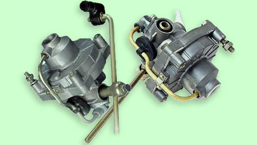
Pressure regulator drive: 1 - pressure regulator; 2, 16 - pressure regulator mounting bolts; 3 - arm of the pressure regulator drive lever; 4 - pin; 5 - pressure regulator drive lever; 6 - axis of the pressure regulator drive lever; 7 - lever spring; 8 - body bracket; 9 - pressure regulator mounting bracket; 10 - elastic lever of the pressure regulator drive; 11 - earring; 12 - earring bracket; 13 - washer; 14 - retaining ring; 15 - bracket pin; A, B, C - holes
It is particularly noteworthy that these contours do not necessarily connect the wheels of the same axle. As for the part like vacuum amplifier, it is necessary to improve the operation of the entire braking system and reduce the driver's efforts during braking. This amplifier comes with a master cylinder. The main body of the amplifier consists of a chamber divided into two parts by a rubber diaphragm. By varying the pressure and sufficient diaphragm area, the pedal support force can be significantly reduced. You can replace the broken part of yourself, or do it in the garage.
The pressure regulator VAZ 2114, VAZ 2115, VAZ 2113 is attached to the bracket 9 with two bolts 2 and 16. In this case front bolt 2 simultaneously fastens the forked bracket 3 of the lever 5 of the pressure regulator drive. A double-arm lever 5 is pivotally attached to the finger of this bracket by a pin 4. Its upper shoulder is connected to an elastic lever 10, the other end of which is pivotally connected through a shackle 11 to the rear suspension arm bracket.
The bracket 3, together with the lever 5, due to the oval holes for the fastening bolt, can be moved relative to the pressure regulator. This regulates the force with which the lever 5 acts on the piston of the regulator (see the chapter "Adjusting the drive of the pressure regulator VAZ 2113").
Brake distribution for. Mechanical damage Metal corrosion Defective pistons Transmission malfunction. Cracking or hesitation of the vehicle during braking Increase in brake pedal stiffness Rear wheels not fully captured during braking Increased stopping distance Oil stains or brake fluid on rubber shoes in rear chain Warning signals displayed. Exceeded the recommended service life of parts Insufficient quantity brake fluid Oxidation of pistons Infiltration of air in the chain Depression or deformation of the control lever Damage to shoes Ingress of dust or foreign objects. A faulty trim valve can be very difficult to identify on your own as the signs are similar to those of a brake system failure.

Pressure regulator: 1 - pressure regulator body; 2 - piston; 3 - protective cap; 4, 8 - retaining rings; 5 - piston sleeve; 6 - piston spring; 7 - body bushing; 9, 22 - support washers; 10 - pusher sealing rings; 11 - support plate; 12 - pusher sleeve spring; 13 - sealing ring of the valve seat; 14 - valve seat; 15 - sealing gasket; 16 - plug; 17 - valve spring; 18 - valve; 19 - pusher bushing; 20 - pusher; 21 - piston head sealant; 23 - piston rod sealant; 24 - plug; A, D - chambers connected to the master cylinder; B, C - cameras connected to the wheel cylinders of the rear brakes; K, M, N - gaps
You should check this part every time you change your brake fluid - every 1 or 5 years. The average service life of this valve is about 2 years. The compensation valve does not repair itself. In case of failure, it must be replaced. In the event of a serious problem or system failure, you can temporarily disable the valve. To do this, connect the master cylinder directly to the rear circuit.
To replace the valve, unscrew the bracket from two exhaust pipes in room. The part must be replaced by a mechanic. After a long period of highs and lows, Magura returned for several years with a conviction in the area of disc brakes on mountain bikes with very interesting systems.
There are four chambers in the Lada Samara 2 regulator: A and D are connected to the master cylinder, B - with the right one, and C - with the left wheel cylinders of the rear brakes Lada Samara 2.
In the initial position of the brake pedal, the piston 2 is pressed by the lever 5 through the leaf spring 7 to the pusher 20, which under this force is pressed against the seat 14 of the valve 18. In this case, the valve 18 is pushed away from the seat and a gap H is formed, as well as a gap K between the piston head and the seal 21. Through these gaps, chambers A and D communicate with chambers B and C.
When you press the brake pedal, the fluid through the gaps K and H and chambers B and C enters the wheel cylinders of the VAZ 2115 brake mechanisms. With an increase in fluid pressure, the force on the piston increases, tending to push it out of the body. When the force from the fluid pressure exceeds the force from the elastic lever, the piston begins to move out of the housing, and after it the pusher 20 moves under the action of the springs 12 and 17 together with the sleeve 19 and rings 10. In this case, the gap M increases, and the gaps H and K decrease ... When the gap H is completely selected and the valve 18 isolates chamber D from chamber C, the pusher 20, together with the parts located on it, stops moving after the piston. Now the pressure in chamber C will change depending on the pressure in chamber B. With a further increase in the effort on the brake pedal, the pressure in chambers D, B and A increases, piston 2 continues to move out of the body, and sleeve 19 together with O-rings 10 and plate 11 under increasing pressure in chamber B, it shifts towards plug 16. In this case, the gap M begins to decrease. Due to a decrease in the volume of chamber C, the pressure in it, and therefore in the brake drive, increases and will practically be equal to the pressure in chamber B. When the gap K becomes equal to zero, the pressure in chamber B, and therefore in chamber C, will increase in a smaller degree than the pressure in chamber A due to throttling of the liquid between the piston head and the seal 21. The relationship between the pressure in chambers B and A is determined by the ratio of the difference between the areas of the head and the piston rod to the area of the head.
With an increase in the load of the car, the elastic lever 10 is loaded more and the force from the lever 5 to the piston increases, that is, the moment of contact between the piston head and the seal 21 (see Fig. 6.4) is achieved at a higher pressure in the master brake cylinder. Thus, the efficiency of the rear brakes increases with increasing load.
In case of failure of the brake circuit "right front - left rear brakes VAZ 2114" O-rings 10, bushing 19 under fluid pressure in chamber B will move towards plug 16 until the plate 11 stops in the saddle 14. The pressure in the rear brake will be regulated by the part of the regulator that includes into itself piston 2 with a seal 21 and a sleeve 7. The operation of this part of the regulator, in the event of a failure of the named circuit, is similar to the operation in a working system... The nature of the pressure change at the outlet of the regulator is the same as with a working system.
In case of failure of the brake circuit "left front - right rear brakes" by the pressure of the brake fluid, the pusher 20 with the sleeve 19, the O-rings 10 is displaced towards the piston, pushing it out of the housing. The gap M increases and the gap H decreases. When the valve 18 touches the seat 14, the pressure rise in chamber C stops, that is, the regulator in this case works as a pressure limiter. However, the achieved pressure is sufficient for reliable operation of the rear brake.
A hole is made in the body 1, closed by the plug 24. The leakage of liquid from under the plug when it is squeezed out indicates the leakage of the rings 10.
Replacing the brake pressure regulator
Both the fork and frame have a rack mount for 180mm discs, so there is no need to install any adapter. The first was found only on two-component pillows, the second on both types of pillows, and the third only on monoplate pillows. While the two-piece pads use classic mounting bolts, the one-piece shims do not require this and rely on two “hooks” that rest on the caliper body. A very practical magnetic cushion retention system, thanks to which the cushions are attached to the pistons without the use of classic clothespins.
When braking, the vertical reactions on the front and rear wheels are redistributed in such a way that they increase on the front wheels and decrease on the rear ones, since the car “bites” under the influence of inertia forces.
With the same pressure in the brake drives of all wheels, their braking mechanisms create an equal braking force, and this can lead to blocking (movement without rolling - sliding) of the rear axle wheels and, as a result, to a skid of the car.
How does the brake pressure regulator work when braking a car?
The brake point register is in a comfortable position, but it is not easy to work with worn gloves. More than a doubt also about the effectiveness, since the transitions from one extreme to the other, there are no big differences. As the shims wear, the distance of the lever must be compensated to maintain a constant braking point. If your hands are large enough, irritation is relative, otherwise problems may arise. The lever-distance register, located on the head of the lever itself, is instead easily operated even with gloves and provides a wide range of adjustment.
This negative factor can be eliminated by differentiating the braking forces between the wheels depending on the degree of their power contact with the road - the more the wheel is pressed against the roadway, the more braking force should be applied to it. If the wheel has practically no contact with the road (does not press on it), then it makes no sense to brake with such a wheel - it will simply stop rotating and will slide along the surface of the road surface (blocked). On modern cars to differentiate the braking force between the wheels, brake force regulators are used in combination with anti-lock braking systems.
Checking and adjusting the "sorcerer"
Measuring the distance from the top of the lever to the handle, it actually goes from the 55mm position closest to 90mm from the farthest, two values that suit both shovels for hands and a fairy's hand. However, I personally have no problem using them with one finger, although the obvious disadvantage of increased exposure in the event of a drop compared to the more compact lever remains. Personal preference aside, a two-finger lever in a factory designed specifically for gravity disciplines doesn't make a lot of sense.
Brake force regulators limit the braking forces at the rear axle of the vehicle depending on the pressure in the brake actuator. Proportional to the force of pressing the brake pedal and the change in the load on the rear axle. They can be installed in both hydraulic and pneumatic brake drives. Structurally and according to the principle of operation, such regulators may differ significantly, but their purpose is the same - to redistribute the braking force between the axles, depending on the degree of contact (pressing) of the wheels of one or another axle with the road.
The most widely used brake force regulators with proportional valve and beam brake force regulators.
Possible regulator malfunctions
To accommodate the detail, Magura later introduced both sophisticated and pluriregolabili, but inexplicably, the brakes are still offered with two finger levers. Uncle Jimbo's rear brake route is internal to the frame, so the hydraulic hose must be cut and retightened. At the end of the operation, the stroke of the handle lengthened slightly and the sensation became slightly spongy. To restore perfect functionality, there was no need for a purge, but it was enough to connect a syringe with a small amount of oil on the pumping side and suck in some of the air that entered the plant.
Brake force regulator with proportional valve
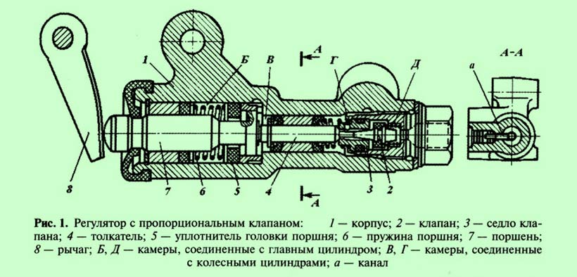
Regulator with proportional valve ( rice. 1) is used in the hydraulic drive passenger cars with diagonal action of the contours. Through it, the brake fluid is supplied to both rear wheel cylinders.
Frame 1 the regulator is rigidly fixed to a bracket installed on the lower part of the car body. On the piston 7 leverage 8 connected to the beam through an elastic metal arm or spring.
A second syringe without a plunger connected to the pump port acts as an "expansion vessel". The assembly did not require any other specific operation, and the banjo connector allows the tube to be oriented to fit the shape of the frame.
Braking power must be sold and, more importantly, not brutally delivered. The "coherent" feel offered by the lever at the moment when comic book pads allow highly accurate brake transmission to the steering wheel, avoiding both the digital effect of some very powerful systems and the sponginess of other especially modulated levers. The heat resistance is very good and the braking spaces do not expand even after long and continuous descents. The lever travel and hand feel that remain constant allow you to disconnect the latter without fear of unpleasant surprises.
The home position of the brake pedal camera B and D related to the main brake cylinder, connect to cameras V and G... When you press the brake pedal with an increase in the pressure of the brake fluid in the chambers V and G, piston 7 and pusher 4 will begin to move out of the body, which will lead to the landing of the valve 2 in the saddle 3 and the overlap of the rear wheel lines.
For heavier use, or if you prefer a sharper response, a 203mm disc is the ideal choice instead. After several months of use with little or no Maintenance and without cleaning, the pistons still fit perfectly, so eliminate the slicer effect and the nervous system. For more than 25 years, the Russian SUV has found a happy welcome both in the third world and in the "dead West". More alarming to common sense is the price of the samples used - especially against the background of the abundance of SUVs - the second hand of any kind.
With increasing load, the car body is displaced relative to the axle beam and the lever force 8 on the piston 7 increases, i.e. piston extension 7 and further operation of the regulator mechanism will occur at a higher pressure in the master brake cylinder, which will increase the efficiency of the rear brakes.
Adjusting the position of the brake adjuster
Like almost everything that was produced in Russia, the explanation for this phenomenon is rooted in the inexpensive and cheap support that Lada-Niva requires. Thanks to its image, it also possesses excellent driving qualities and unpretentious mechanics, whose similarity to other VAZ vehicles makes maintenance easier. Therefore, it is not surprising that a jeep with an agricultural name continues to search in our country, and prices are almost unrelated to the age of the car.
It is not uncommon for some owners to make more money on their Levels than when they bought. A year later, the body is also being upgraded. Changes include new taillights, the shape of which allows the luggage compartment to reach the bumper and thus greatly facilitates access to the cargo area.
In the event of failure of one of the diagonals of the hydraulic drive, the regulator ensures the operation of the serviceable line in normal mode.
The regulators installed in the hydraulic drive with the distribution of the circuits over the axles have a simpler design, since they have only one chamber connected to the main brake cylinder and one to the wheel cylinders.
Permanent four-wheel drive vehicles and the maximum combination of units with other VAZ models is still used by fans of a cheap SUV, and for many more modest drivers in regions with a poorly developed and maintained road network, the Russian jeep remains the optimal solution. After so many years on home roads weak spots Lada-Niva is no longer a secret. The same goes for positive qualities... However, the encyclopedia of the truth that Russian technology can always surprise is also applicable to the VAZ.
The quality of cars, for example, does not depend on the year of production. Poor people even advise giving preference to older cars than those that were in the early 90s. After all, in a long-standing socialist tradition, the buyer must rely on the "batch". However, the owner of the candidate can put some highlights in the guise of the selected specimen and thus save their headaches.
Beam brake force regulator
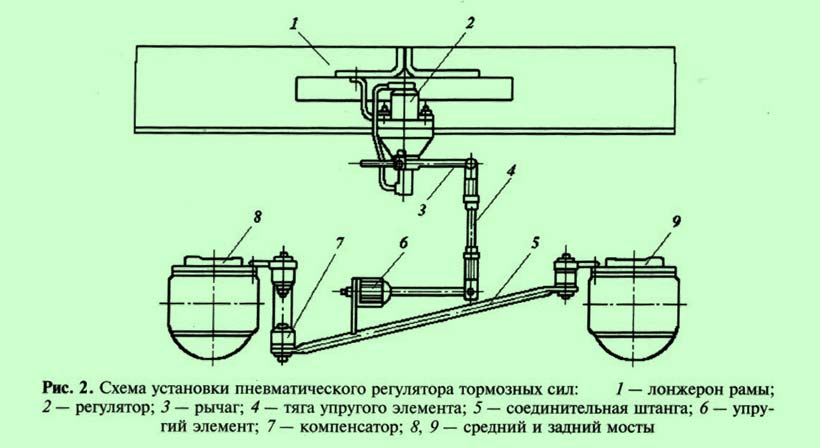
In the pneumatic brake drive of the KamAZ-5320 vehicle, a brake force regulator is used, which allows you to change the air pressure in the brake chambers of the wheels of the rear bogie, depending on the vertical load on the axles at the time of braking. The interdependence of the air pressures in the circuits of the front wheels and the rear bogie, which is provided by the action of the regulator, is an inclined straight line (beam), therefore such regulators are also called radial. It is installed on the frame cross member in a vertical position and has a flexible mechanical connection with the bridge beams ( rice. 2).
The neutral point in a Russian SUV is transmission. The permanent four-wheel drive simplifies construction, but also significantly increases damping when using conventional flooring. The splitter and the gearbox are "split", and the torque between them is transmitted from the short shaft of the shaft. It belongs to him that the characteristic dragging out of all "Levels" occurs. The almost symphonic noise that the Russian Jeep uses to bombard the ear often prevents problems with certain parts of the chassis.
Checking the pressure regulator
However, according to the opinion, everything should be done to detect unnatural sounds. The reasons for their early decommissioning may be a surge at the plant. The front axle hinges are also weak. Typically, most assemblies suffer from premature material fatigue and adequate amortization. Only the delimiter field can be used as relatively seamless.
Beam regulator ( rice. 3, a) has a two-piece body 2
and 9
between which the membrane is clamped 16
... Large stepped piston 14
membrane bound 16
by means of an annular spring 5
, there is a valve inside the stepped piston 13
with spring 12
pressing him to the saddle.
Inclined ribs are made on the piston around the perimeter 7
.
In the upper case 9
a fixed insert with similar inclined ribs is inserted 6
, the lower edges of which run along the border with the membrane. Ribs 7
the piston is between the ribs 6
fixed insert. If the piston 14
is in the upper position, then its ribs do not touch the membrane 16
, and it rests on the piston only in the middle part, while the rest of the membrane is adjacent to the fixed ribs 6
inserts. The lower active area of the membrane in this case is minimal.
The movement of the engine gas distribution from the circuit should not appease the candidate buyer. Practice shows that after 50 thousand kilometers, as a rule, it is necessary to stretch it. The owner must tighten the hearing again to avoid a harder investment. Then it is also clear that the "batch" is good - if engine fatigue is not felt, the buyer is in luck.
Among the others possible repairs that make up the family budget, the most problematic is the problematic starter, water and fuel pump... A carburetor with a 6-liter engine constantly needs adjustments, because otherwise the cost becomes astronomical. Sometimes the fuel level in its chamber drops by a sharp turn. The plastic parts of the distribution cap are broken, sparking becomes chaotic. The 7-liter engine suffers from disadvantages. Uncertain acceleration and thrust are only eliminated after correct adjustment of the spray system.
When lowering the piston 14 his ribs 7 begin to rely on the membrane 16 , and at the same time it moves away from the fixed ribs 6 inserts. The lower active area of the membrane increases. Thus, the ratio of the pressures on the membrane 16 from below and to the stepped piston 14 from above is equal to the ratio of their active areas.
The active area of the upper side of the piston is constant, while the active area of the diaphragm changes depending on the position of the piston.
In the middle part of the regulator body there is a movable pusher 15
resting on a ball heel 18
connected through the linkage system with the bridge beams, therefore the position of the pusher 15
depends on the deflection of the rear bogie springs, i.e. the load.
The piston is located at the bottom of the pusher 19
, the cavity under which is connected by a tube 1
with conclusion I
air supply to ensure constant compression of the ball joint 18
to the pusher 15
... Through this output, the regulator is connected to the upper section of the brake valve of the service brake system, through the output II
with brake chambers for the wheels of the rear bogie. Output III
through the valve 3
connects the internal cavity of the regulator to the atmosphere.
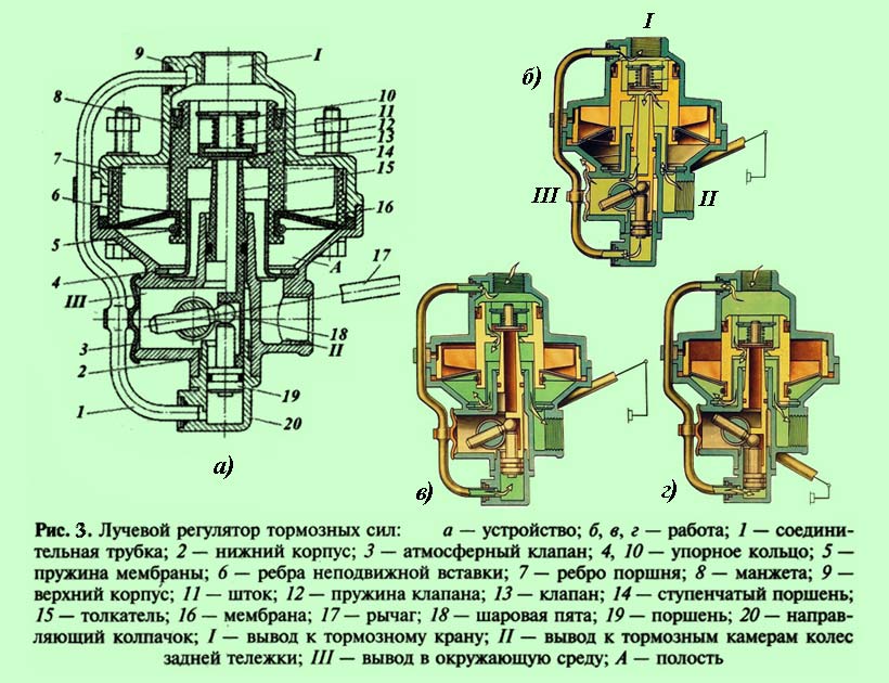
In the absence of braking ( rice. 3, b) the piston is in the upper position, the valve 13 closed and does not rest against the pusher seat. In this case, the brake chambers through the outlet II , inner channel in the pusher and outlet III connect with the atmosphere.
When braking ( rice. 3, in) air is supplied to the regulator through the outlet I and piston 14 moves down. At a certain moment, the valve 13 rests against the pusher saddle 15 and will close its internal channel, therefore, the brake chambers will be disconnected from the environment (atmosphere). Following this, the valve 13 leaves the seat in the piston and the compressed air flows through the valve and the annular gap between the pusher and the piston to the outlet II and further to the brake chambers.
The follow-up action of the regulator is carried out as follows. The air supplied to the brake chambers simultaneously enters the cavity A and with the same pressure presses on the membrane 16
from below. Upon reaching a certain compressed air pressure, the piston 14
with membrane 16
go up.
Once the valve 13
sits in the piston seat, the supply of compressed air from the outlet I
in conclusion II
will stop.
The operation of the regulator when the load on the rear bogie changes will be carried out as follows. At maximum load, the linkage, acting on the ball heel 18 , will move the pusher 15 to the top position. To open the valve 13 slight piston movement required 14 at which its ribs 7 do not fall below the ribs 6 fixed insert. Active membrane area 16 in this case, it will be insignificant, and the lift of the piston 14 upward will occur at greater pressure in the cavity A from the bottom of the membrane, which means that compressed air will be supplied to the brake chambers of the rear bogie under high pressure.
With minimal axial load distance between rear axles and the regulator will be the largest ( rice. 3d). Pusher 15
at the same time it will go down to the lowest position, and to open the valve 13
in order to supply compressed air to the outlet II
piston 14
should go down as much as possible.
In this case, his ribs 7
fall below the ribs 6
fixed insert, which will lead to a maximum increase in the active area of the diaphragm 16
... Consequently, the equilibrium position will come at a much lower pressure in the cavity A, which means that the pressure of compressed air in the brake chambers in this case will be much lower.
Thus, the regulator in automatic mode differentiates the braking forces between the wheels front axle and the rear bogie in proportion to the distribution of the total load on the vehicle between its front axle and the rear bogie. In this case, the regulator takes into account not only static loads (vehicle weight), but also inertial loads that occur when the vehicle speed changes.