3.2.1. The oil level in the crankcases of the E-500 compressors must be at least 15 mm from the upper edge of the filling hole, and in the KT-6, KT-7, KT-8, 1-KT, PK-35, PK-5.25, VV compressors -3.5 / 9, VP-3-4 / 9, K1, K2, KZ - between the upper and lower risk of the oil indicator.
The oil level in the crankcases of the compressors exceeding the limits of the oil gauge control marks is not allowed in operation.
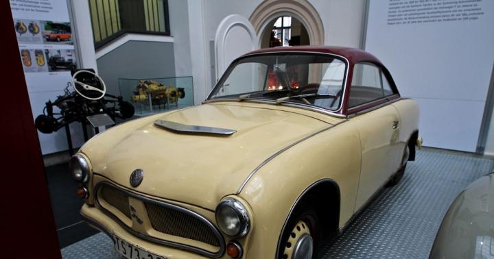
It is stored on the main frame using macroblocks. The cab entrance is a pair of diagonally positioned doors that allow the cab to exit directly onto the locomotive rails. The entrance doors of the cab are locked using uniform keys. The cabin is sound and heat-insulated. With a lower rear cowl at the rear of the cab, a large windshield... Other cab windows are original. Door windows and door windows are equipped with windscreen wipers. The windshield control is split between the two stations, so that each seat is always controlled by a wiper and a second wiper button in the tailgate window.
For compressors of electric locomotives, K-12 oil is used (in winter period) and K-19 or KS-19 (in summer); for locomotive compressors - K-19 or KS-19 compressor oil year-round.
Oil of the KZ-10 n brand is used for lubrication of ChS series compressors all year round up to an ambient air temperature of -30 ° C, and for electric locomotive compressors of the remaining series in winter up to an ambient air temperature of -30 ° C.
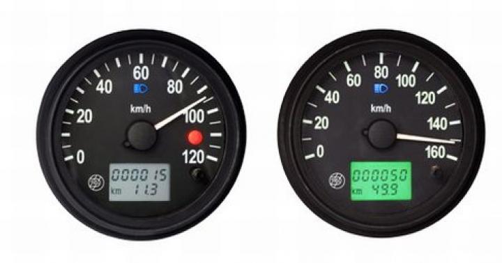
An adjustable sun visor is installed in front of the front windows to prevent glare. There are two control panels inside the cab. They include both directional movements and directional levers, pneumatic brake adjusters, measuring instruments, electronic speedometer, signal repeater, alarm and controls. The devices are equipped with their own lighting, the intensity can be adjusted. Other controls are located on the panel on the side of the second control console or on the panel above the first control panel.
KZ-20 oil is used to lubricate compressors of all series year-round, and for electric locomotive compressors (except for the ChS series) as a summer oil and during a transitional off-season period up to an ambient air temperature of -15 ° C.
The lubricators of the steam-air pumps must be completely filled.
Before starting the compound pump, the handle of the grease nipple should be turned manually until oil appears in the control nipples of the oil lines.
Several controls and switches are also located in electrical distribution boards, accessible from both the cab and the locomotive rails. The cabin has a sink. The water tank is located at the front of the lid. The tank is filled with pressurized water through a pipeline located in the engine room on the right. The amount of water in the tank is indicated by an optical barrier. An electronic sensor is installed on the tank low level water, the condition is indicated by a red lamp in the cockpit. The tank is equipped with heating with a heating cable.
To lubricate the steam part of the steam-air pumps, it is necessary to use K-12 cylinder oil.
Do not use other types of oils to lubricate compressors and steam-air pumps.
When the locomotive is handed over from the depot after Maintenance(except for TO-1) and repair, the performance of its compressors should be checked by the time of filling the main tanks from 7.0 kgf / cm 2 to 8.0 kgf / cm 2 (Appendix 1).
There is a switch in the power supply of the inverter to turn on the inverter. The drive is signaled by a green control light on the inverter. Inverter and socket circuit protection is provided by the circuit breaker and circuit breaker. First, turn on the power to the inverter using the switch located in the right box on the right. Wait for the inverter operation indicator to light up, then turn on the socket protection cover located to the left of the connector.
The front hood is from the original locomotive. New movable louvers are located above the cooling unit and hard shutters in the cover under the cooling unit on the right side of the air conditioning condenser. Further changes in the bonnet are related to the modification of the new bearing components that are installed on the bonnet. The back cover is newly designed. There is an electrical Switchgear and part of the rechargeable battery. Adapted lights and spotlights. They are controlled by combined controls located on the driver's control panels.
3.2.2, Check the tightness of the brake and supply lines with the train position of the auxiliary brake valve handle and the driver's valve, the combined valve is closed and the compressors are not working. The pressure drop indicated by the pressure gauge should be:
in TM with normal charging pressure by no more than 0.2 kgf / cm 2 for 1 minute, or 0.5 kgf / cm 2 for 2.5 minutes;
Individual switch positions can be selected by a combination of signal lights. The button is also attached to the top white warning light. To control the headlights, switches on each driver's control panel can control the headlights from both the front and rear of the locomotive.
During the reconstruction of the locomotive, there were minor changes in the pneumatic equipment. Installed automatic automatic brake with electric drive. A direct-acting electric drive with an electric drive is installed. Added locomotive brake control.
in the feed line with 8.0 kgf / cm 2 by no more than 0.2 kgf / cm 2 for 2.5 minutes, or no more than 0.5 kgf / cm 2 for 6.5 minutes. Before the specified check, the locomotive must be secured.
3.2.3. Check:
the density of the equalizing tank at the driver's cranes No. 394 (395), for which to charge the locomotive brake network to normal charging pressure, move the driver's crane handle to position IV. The density is considered sufficient if the pressure drop in the surge tank (UR) does not exceed 0.1 kgf / cm 2 for 3 minutes. Overestimation of pressure in the UR is not allowed in this case;
On the first chassis, the valve with the valve is located separately, and its supply is made from the tool reservoir. The valve for the second chassis is part dashboard... The lubricant is stored in the store, from where it is fed to the rectifier nozzles wheel rims... The lubricant reservoir is fed through the tap, filter and nozzle with compressed air from the supply line. This grease travels through the check valve and filter to the dispensing area of the nozzle. Here, the second air is supplied with 5 bar compressed air, which transfers the lubricant from the metering area of the nozzle to the wheels.
Air is started by email. A valve that is switched by the speedometer depending on the trajectory traveled. The shut-off valve is located on the pipe near the valve. With the two-hand steering, the direct braking effect is also transferred to the driven locomotive, so that both brakes are simultaneously. Most of the direct acting brakes are located on the braking panel, which is located in the engine room of the locomotive. The only exception is the brake controls located on the control panels.
on the sensitivity of air distributors (VR) to braking by lowering the pressure in the UR of the driver's cranes No. 394.395 in one step by 0.5 kgf / cm 2, and with the VR, which acts through the valve No. 254 - 0.7-0.8 kgf / cm 2 ... In this case, the air distributor should work and not give spontaneous release within 5 minutes. When the BP is triggered, it should light up, and after filling the brake cylinders, the TM lamp should go out of the train brake line rupture indicator. After braking, make sure that the piston rods come out of the brake cylinders and the pads are pressed against the wheels;
A direct acting brake uses compressed air from a locomotive power line. This air on the brake panel passes through the shut-off valve and is then brought to a value of 4 bar at pressure reducing valve, which is the maximum value brake pressure direct action. By controlling the brake actuators, voltage is applied to a pair of electro-pneumatic valves that control air inlet to the direct brake. The braking of the direct brake is caused by a power cut to both valves.
As soon as the unloading valve is unloaded, it closes to prevent air from escaping from the rectilinear brake circuit. In contrast, a non-actuated brake valve forces air to enter the brake. The pressure switch, in its function, copies the pressure changes in the control line and changes the pressure conditions on its output line. Air pressure from the supply line is fed to the pressure switch through a shut-off valve and filter. The shut-off valve serves to close the air supply, for example, in a situation where a locomotive is pulled on a train like a carriage.
on the sensitivity of the air distributors to the release by setting the driver's crane handle No. 394 (395) to the train position, at which the brake must be released and the pads must move away from the wheels;
elimination rate over charge. To do this, after releasing the brake, move the driver's crane handle No. 394 (395) to 1 position, hold it in this position until pressure UR 6.1-6.3 kgf / cm 2, followed by transfer to the train position. A decrease in pressure in the UR from 6.0 to 5.8 kgf / cm 2 should occur in 100-120 seconds; on a locomotive that has a brake line rupture indicator with sensor No. 418, the indicator should not be triggered during the transition from high pressure to normal;
During direct braking, air is directed through the pressure switch to the double check valve, which uses the same lines as the spontaneous brake of the brake cylinders. This also applies to pressure gauges, which show the air pressure in the brake cylinders even when using a direct brake. The pressure switch is connected to the output line of the pressure switch to automatically block the train. Direct braking is fully electric and controls the respective valves via cam switches.
auxiliary brake for maximum pressure in the brake cylinders (TC). This pressure should be 3.8-4.0 kgf / cm 2, and on diesel locomotives TEP70 and 2TE10L at gear ratio lever transmission of the brake 10.77 and on steam locomotives P36, FDp, Su - within 5.0-5.2 kgf / cm 2. After activating the auxiliary brake with the maximum pressure in the shopping center on the locomotive, which has a brake line rupture indicator, reduce the pressure in the surge tank by 0.2-0.3 kgf / cm 2 and, after the TM lamp comes on, set the position with the driver's controller. The thrust pattern should not collapse. Then increase the discharge to 0.6-0.7 kgf / cm 2 - the TM lamp should go out.
The controller consists of five positions, with three locks and two unattached positions. The air pressure indicators in the brake cylinders provide pressure switches that switch at a pressure of 0.3 bar. When the switch contact is energized, an indicator on the driver's control panel comes on. This is recorded in the memory of the electronic speedometer.
Used brake system provides gradual braking and braking. The filling and emptying of the brake cylinders is controlled by the brake valve depending on the change in the air pressure in the main pipe. The brake valve enters the air from the auxiliary reservoir to the brake cylinders. On the other hand, when the brake cylinders are released, the air is released through the brake valve into the air. Two self-locking reservoirs are connected to the brake. This is a 2.5 liter tank and a 5 liter low pressure tank.
The density of the surge tank and the elimination time in excess of the charging pressure when the locomotive is released from the depot after repair and maintenance (except for TO-1) should be checked when a leakage from the brake line of the locomotive through a 5 mm diameter hole in the removable head of the end valve. Together with the indicated air leak
Depending on changes in the pressure in the control tank, the pressure ratios in the main line are also changed through the synchronization valve. The brake is filled with compressed air through the exhaust pipe at a nominal pressure of 5 bar in the main line. The exhaust duct from the brake is equipped with air filter, shut-off valve and three-way extractor with drain cock. The main line leads to both ends, forks and ends with clutch valves with brake couplings. Suspension couplings are mounted on plows.
The chronometric air reservoir is connected to the brake valve, which serves as a standard for automatic braking and maintains the nominal air pressure in the line. The brake valve then compares this value with the air pressure in the main line and controls the braking and release accordingly. The pressure switch is connected via a 2.5-liter control reservoir that functions as a dummy brake cylinder. Thus, the time for filling and unloading the brake cylinders does not depend on the piston stroke, that is, on the displacement volume.
check the operation of the driver's crane No. 394 (395) in III position. At this pressure in TM and UR should be continuously decreasing.
Table 3.1.
Stem exit brake cylinder on locomotives and multi-unit rolling stock with full service braking
|
Type of rolling stock |
Brake cylinder rod output, (mm) The controller has five locks and two loose positions. It then controls the intake of air into the main channel, thereby controlling the supply of air to the brake cylinders through the brake valve. Self-defense controls are blocked from being used in an inactive location. An exception is the quick brake position, which can also be entered from the inactive driver's control panel. The current air pressure in the brake cylinders is displayed on the pressure gauges on the driver's control panels. It is possible to control two connected 742 series locomotives driven from the same station. The rebuilt locomotive can be combined with the original series of locomotives. |
|
|
Maximum in operation |
||
|
Electric locomotives, diesel locomotives (except for TEP 60, TEP 70), passenger steam locomotives |
||
|
Diesel locomotives TEP 60, freight steam locomotives |
||
|
All series steam locomotives tenders |
||
|
Electric locomotive cars ER2, ER9 (all indexes): motor, |
||
|
head and trailed The initial state for blocking is locomotives face to face. Disconnectors rechargeable batteries disabled. Brake locomotives - automatic brake, direct brake or brake parking brake. Turn off the circuit breaker. Train guard. On direction control levers and control lever in zero position. Connect two locomotives with a screwdriver. Blow out and connect the main pipe to reveal the clutch loops. Connect the two-wire control cable. If the supply pipe connecting hoses are 900 mm long, connect this pipe. |
||
|
Head and trailer cars of electric trains ER2t, ER2r, ER29, ED2T, ED9T, ED4, ED4M |
||
|
Electric train carriages of other series: motor |
||
|
head and trailed |
||
|
Motor and trailer diesel cars - trains: with disc brakes |
||
|
with shoe brakes If both locomotives are crossing bridges, lower them to a horizontal position. Coupling of modernized locomotives. Close the battery isolator and check that the circuit breaker is closed. Select the station from which you will drive the locomotive. Move the directional arm to its original position on the active console. Start the engine internal combustion... Switch on the circuit breaker. Select the desired direction of travel on the active console using the directional lever. Both locomotives are still equipped with a handbrake. When connecting a pair of retrofitted locomotives, there is no need to connect a direct-acting brake pipe as it is electrically controlled by a two-wire steering cable. |
||
|
Trailed wagons with composite blocks (without bushing length) |
||
* - in winter - 12 mm.
Notes:
1.The output of the rod of the brake cylinders of electric trains at the braking stage is less than the specified value by 30% at
the location of the brake cylinders on the car body and by 20% when the brake cylinders are located on the bogie.
2. If there are norms for the output of the rods established by the factory instructions and agreed with the UZ, be guided by these norms. The maximum allowable stem exit is set 25% more than the upper limit when discharged from the depot.
3. Diesel locomotive TEP70 must have a brake cylinder rod outlet; size B with the brake released 340-365mm. (520mm. Maximum in operation).
3.2.4. When the locomotive leaves the depot, the outputs of the brake cylinder rods must be within the limits specified in Table 3.1. at a pressure of 3.8-4.0 kgf / cm 2.
When locomotives and MVPS are released after maintenance (except for TO-1) and repair of brakes, the linkage must be adjusted to the amount of the rod exit in accordance with the minimum permissible norms.
3.2.5. The thickness of cast-iron brake pads in operation is allowed at least: ridgeless on tenders - 12 mm, ridge and sectional on locomotives (including on tenders) - 15 mm, on shunting and export locomotives - 10 mm. Exit of brake pads beyond the outer surface of the rim (wheel rim) in operation is allowed no more than 10 mm. Replace the pads: when the maximum thickness is reached, there is a crack along the entire thickness of the pads, which reaches the steel frame, with wedge-shaped wear, if the smallest permissible thickness is from the thin end of the pads at a distance of 50 mm or more.
3.2.6. The charging pressure of the brake line in the train position of the driver's crane handle (driver's RCM) must correspond to the values indicated in Table 3.2.
Table 3.2.
Brake line charging pressure
|
Train characteristics |
Charging pressure in TM of the leading locomotive, MVPS (kgf / cm 2) |
|
1. Electric train ER (except ER22, ER2t); train with a set of non-operating wagons |
|
|
electric trains ER (except ER22, ER2t); freight train with wagons |
|
|
electric trains ER (except ER22, ER2T) or empty tenders with included |
|
|
auto brakes. |
|
|
2. Electric train ER2t (and trains in which it is located). |
|
|
3. Freight train with a set of empty wagons, a passenger train, which includes |
|
|
followed by cars with automatic brakes such as KE, Oerlikon, DAKO. |
|
|
4. Passenger, cargo-passenger, rafts, which include passenger |
|
|
locomotives; freight in the presence of the MVPS wagons (except for the wagons of electric trains |
|
|
ER) and passenger locomotives and carriages with automatic brakes on, multi-unit; |
|
|
separate passenger locomotive. |
|
|
5. Freight, which includes a multiple-unit wagon with a cargo auto mode, a raft with |
|
|
a train of freight locomotives, a separate freight locomotive. |
|
|
6. Diesel trains of the DR1A, DR1P series. |
|
|
7. Freight on long slopes 0.018 and more; freight, which includes |
|
|
air diffusers No. 388 of rigid type. |
|
|
8. Freight train, which includes loaded wagons and which goes to |
|
|
a long-distance path that does not have steep long descents of 0.018 or more. |
According to local conditions, based on experimental trips, by order of the head of the road, the charging pressure can be set:
On long descents with a steepness less than 0.018 for loaded freight trains 6.0-6.2 kgf / cm 2;
On long descents from 0.018 to 0.028 for empty freight trains 5.3-5.5 kgf / cm 2 (allowed by a separate indication of UZ)
3.2.7. Modes of switching on of air distributors (BP):
when driving freight trains at a speed of no more than 90 km / h and when performing shunting works BP cargo type on locomotives, turn on empty mode, and when following freight train at a speed of more than 90 km / h, turn on the BP on the locomotive to the loaded mode. On long descents with a steepness of up to 0.018 ВР of the cargo type, switch to the flat mode, with a steepness of 0.018 and more - to the mountain mode. BP No. 292, regardless of the steepness of the long descent and speed, turn on the long-section mode. Switch on to the mountain mode regardless of the slope of the descent of the BP of locomotives, in which the release of the automatic brake is provided by the release of air from the working chamber of the air distributor.
when handling passenger and cargo passenger trains BP locomotives include: No. 270, 483 - for laden and flat mode, No. 292 in passenger trains with up to 25 wagons inclusive - on mode "K" (short-train and normal length trains), and in passenger trains with more than 25 wagons and for freight-and-passenger - trains on the "D" mode (trains of increased length).
in case of a single passage of a freight locomotive BP, switch it on to the loaded mode, and switch on the mode “K” for passenger and cargo-passenger VR No. 292.
If, when locomotives are connected according to the system of many units, the action of the auxiliary brake crane of the first locomotive does not apply to subsequent locomotives, then the BP on these locomotives is switched on to medium mode.
When connected to a single freight locomotive, no more than five wagons, or five inactive locomotives, switch its BP to loaded mode.
When performing shunting operations and movements of freight-type VR on train and shunting locomotives, which are serviced by one driver, turn on the loaded mode.
3.2.8. When the locomotive is released after its servicing (except for TO-1) and repairs, it is necessary to check the air flow through the blocking device No. 367 and through the driver's crane. The check is carried out at an initial pressure in the main reservoirs (GR) of at least 8.0 kgf / cm 2 and with the compressors turned off in the range of pressure reduction in the GR with a volume of 1000 liters from 6.0 to 5.0 kgf / cm 2. The permeability of blocking No. 367 is considered normal if, when the operator's crane handle is in the first position and the TM end valve is open from the side of this device, the pressure drop takes no more than 12 seconds.
The passage of the driver's crane is considered normal if, when the driver's crane handle is in position II and the end valve is open, the pressure drops within the specified limits within a time period of no more than 20 seconds. With a larger volume of the locomotive's GR, the time should be proportionally increased.
3.2.9. Check the operation of the electro-pneumatic brake (EPB) equipment on locomotives from both control cabins in the following order:
To check the voltage of the EPT power supplies, set the operator's crane handle in the working cabin to the train position, remove the connecting end sleeve from the insulated suspension from the side of the inoperative cabin and turn off the redundant power switch. Switch on the EPT power supply and check the voltage using a voltmeter direct current at the IV position of the RKM at the output of the converter, which must be at least 50 V. When the RKM is in the UE, U and IV positions, the value of this voltage under load must be at least 45 V;
to check the operation of the EPT, perform stepwise braking to full, and then perform stepwise vacation. When the RCM is in I and II positions, a lamp with the letter designation "O" should be lit, in positions III and IV - lamps "P" and "O", and in positions V, VE, VI - lamps "T" and "O" ... When the RKM is in the VE position, the discharge of the surge tank and TM through this valve should not occur, but the EPT should act;
to check the redundant power supply of wires No. 1 and No. 2, hang the connecting end sleeves on an insulated suspension from both control cabins, turn on the redundant power switch - at the II position of the RCM, the lamp with the letter designation "O" should be on, and when the toggle switch is turned off, the lamp should go out.
If the driver's valve has the VA position (slow rate of discharge of the UR), which coincides with the position of the CHE, then the pressure in the UR is allowed to decrease not more than 0.5 kgf / cm 2 from the initial charging pressure at full pressure in the brake cylinders.
Some of the above checks are carried out simultaneously.
Brake line charging pressure
| Train characteristics | |
| 1. Electric trains; train with a set of non-operating electric train cars | |
| 2. Passenger; cargo and passenger; freight, which includes loaded wagons with air distributors switched on to medium mode; a raft with a train of inactive locomotives; freight, which includes passenger locomotives and wagons with automatic brakes on; multi-unit, except for electric trains and diesel trains DR1, DR1P, DR1A, DR1B, DRB |
Continuation of table 2.2
| Train characteristics | Charging pressure in the brake line of the leading locomotive, multi-unit train, kgf / cm 2 |
| 3. Diesel trains DR1A, DR1B, DRB | |
| 4. Diesel train D1 | |
| 5. Rail bus RA1 | |
| 6. Freight with a train of empty wagons; passenger, which includes carriages with activated automatic brakes KE, Oerlikon, DAKO; freight, which includes wagons of multi-unit rolling stock (except for electric trains); shunting train | |
| 7. Freight, which includes laden wagons with air distributors switched on for laden mode; freight with a train of empty wagons on long slopes with a steepness of 0.018 and more; diesel trains DR1; DR1P | |
| 8. Freight, which includes electric train cars; freight, which includes empty tenders with included auto brakes |
3. PROCEDURE FOR CHANGING THE CONTROL CABINSON LOCOMOTIVE AND SWITCHINGBRAKE EQUIPMENT
3.1. On locomotives not equipped with blocking device No. 367, in non-working cabins, the combined crane and the isolation valve on the air line from the auxiliary brake valve No. 254 to the brake cylinders must be closed.
Isolation valves on the air supply line, the air line from the air distributor to valve No. 254 and the isolation valve on the air line from the brake line to the speed meter on all locomotives must be open and their handles are sealed. On electric locomotives of the ChS series, a disconnecting valve on the air line from the crane
No. 254 to the brake cylinders must be open. The operator's crane handle must be in the emergency braking or service braking position in the presence of an emergency stop device.
3.2. When a locomotive crew changes the control cabin, the following work procedure must be observed.
3.2.1. In a parked driver's cab not equipped with lock no. 367 or with brake lock no. 267, the driver must:
before leaving the cab, perform emergency braking with the driver's crane No. 328, 394, 395. After the line is completely discharged, move the handle of the combined crane to the double pull position. Before leaving the cab, the driver must make sure that the brake cylinders are filled to full pressure, and if there is a brake lock
No. 267, turn the removable interlock key and remove it from the slot;
Move the valve handle No. 254 to the last braking position and, after filling the brake cylinders to full pressure, close the isolation valve on the air line to the brake cylinders (on electric locomotives of the ChS series, do not turn off the isolation valve), and when servicing electric locomotives of the ChS series by one driver, the valve handle
Leave No. 254 in train position;
in the presence of an electro-pneumatic brake, turn off the power control switch of this brake;
Moving to the working cabin, the driver must:
open the isolation valve on the air line to the brake cylinders from valve No. 254;
move the operator's crane handle from the braking position to the train position, and if there is a brake lock No. 267, insert the removable lock key into the socket and turn it;
open the combination valve by placing its handle vertically upward when the surge tank is filled to the charging pressure;
Move the crane handle No. 254 to the train position. 3.2.2. In an abandoned control cab equipped with an interlocking device No. 367, the driver must:
before leaving the cab, perform emergency braking with the driver's crane and discharge the brake line to zero;
Move the valve handle No. 254 to the last braking position. When full pressure is established in the brake cylinders, move the locking device key from the lower position to the upper position and remove it;
make sure that there is no unacceptable decrease in pressure in the brake cylinders (the pressure in the brake cylinders may be reduced by no more than 0.2 kgf / cm 2 per minute);
in the presence of an electro-pneumatic brake, turn off the power control switch of this brake.
Having entered the working cabin, the driver must insert the key into the locking device and turn it down. After that, move the driver's crane handle to the train position, charge the brake network to the set pressure. The handle of the combined crane in the non-working and working cabins must be in the vertical (train) position. 3.3. During the transition, the driver's assistant must be in the left cab and, using the pressure gauges of the brake line and brake cylinders, control the brake engagement in the working cab. In case of spontaneous release of the locomotive brake, the assistant must activate the hand brake, and on a locomotive not equipped with blocking device No. 367, open the isolation valve on the air line from valve No. 254 to the brake cylinders. On locomotives equipped with a drive hand brake only in one cab, the assistant driver during the transition must be in a cab equipped with a handbrake drive. On electric locomotives of the ChS series, the driver's assistant, before leaving the inoperative cab, must move the handle of the crane No. 254 to the train position. After the locomotive is coupled to the train, there is no need for an assistant driver to stay in the left cab. 3.4. After completing all the operations for the transition to the working cabin, the driver must: before setting the locomotive in motion, check the operation of the auxiliary and then automatic brakes on the brake cylinder pressure gauge; after setting the locomotive in motion, check the operation of the auxiliary brake at a speed of not more than
3 - 5 km / h to the stop of the locomotive. 3.5. On locomotives equipped with driver's cranes remote control, the procedure for changing control cabins should be carried out in accordance with the instructions for their operation.
4. LOCOMOTIVE TRAILER TO COMPOSITION
4.1. Approaching the train, the driver must auxiliary brake stop the locomotive at a distance of 10 - 15 m from the first car and stretch the speed meter tape. At the command of a car inspector or an employee trained in performing operations for testing automatic brakes (hereinafter referred to as a car inspector), the driver must set the locomotive in motion and approach the train at a speed of no more than 3 km / h, ensuring smooth coupling of automatic couplings.
4.2. After coupling the locomotive with the freight train, the driver must check the reliability of the coupling with a short movement from the train. Coupling of a locomotive with passenger, postage and baggage, cargo and passenger trains and with a train fixed with special mechanical stops is checked only by the signal branches of the automatic coupler locks.
Before connecting the sleeves between the locomotive and the first car, the car inspector is obliged to inform the driver about the presence passenger cars , locomotives and wagons of multi-unit rolling stock as part of a freight train, on the loading of freight wagons in the train (loaded, empty), the number of wagons in a passenger train, the presence of wagons with disengaged electro-pneumatic brakes or wagons with Western European brakes that differ according to the principle of operation. Having received the required information, the driver is obliged to adjust the driver's crane by the amount of charging pressure in accordance with Table 2.2 or paragraph 2.2.6 of these Rules and turn on the air distributor of the locomotive to the mode in accordance with the requirements of paragraph 2.2.7 of these Rules. The above-mentioned features of the train must be recorded by the inspector of the wagons in the certificate of the VU-45 form. After attaching the locomotive to the train and the driver's transition to the working cabin, at the driver's command, the driver's assistant must blow through the brake line of the locomotive from the train side by opening three times through the end valve, connect the brake line hoses between the locomotive and the first car (before turning on the power source of the EPT, if any) , open the end valve first at the locomotive and then at the carriage. The driver, together with the car inspector, is obliged to check the correct coupling of the automatic couplers by the signal branches of the locks and a special crowbar, the reliability of the automatic coupler mechanism to the coupling, the correct connection of the sleeves and the opening of the end valves between the locomotive and the first car. When a locomotive is serviced by one driver, a car inspector, after attaching the locomotive to the train and the driver's transition to the working cabin, at the driver's command, must blow through the end valve the brake line of the locomotive from the side of the train and the first car, connect the brake line hoses between the locomotive and the first car (before turning on the source power supply EPT, if any) and open the end valves first at the locomotive, and then at the car. 4.3. With multiple traction, the connection of the sleeves and the opening of the end cranes between the locomotives and the first car is performed by the assistant driver of the first locomotive, and the execution of this work is checked by the driver of the first locomotive together with the drivers of other locomotives and is responsible for the correct execution. In addition, with multiple traction, the driver of the first locomotive, together with the drivers of other locomotives, checks whether the handles of the combination crane (or double traction crane) are set to the double traction position. With multiple traction and maintenance of each locomotive by one driver, the connection of the hoses and the opening of the end cranes between the locomotives is performed by the driver of the second locomotive.
4.4. After attaching the locomotive to the passenger train, opening the end cranes and changing the control cabin, the driver must put the driver's crane handle in position I and hold it for 3 - 4 s, then put it in the train position, in which the train's brake network is charged further.
4.5. After the locomotive is coupled to a freight train with a charged brake network, the driver must increase the pressure in the line above the normal charging pressure. To do this, the handle of the driver's crane must be moved to position I and held in this position until the pressure in the equalizing tank rises by 0.5 - 0.7 kgf / cm 2 higher than the charging pressure to which the driver's crane is adjusted, and then put into the train position.
4.6. After attaching the locomotive to a freight train that is braked or with an uncharged brake network, it is necessary to brake by reducing the pressure in the surge tank by 1.5 - 1.7 kgf / cm 2 before connecting the hoses and opening the end valves. After connecting the hoses and opening the end cranes between the locomotive and the first car, move the driver's crane handle to position I and hold it until the pressure in the surge tank rises by 1.0 - 1.2 kgf / cm 2 above the charging pressure to which the driver's crane is adjusted, after then move the operator's crane handle to the train position.
5. MAINTENANCE OF BRAKECAR EQUIPMENT
5.1. When servicing wagons, check:
condition of units and parts of brake equipment for compliance with their established standards. Parts that do not meet the established standards and do not ensure the normal operation of the brake - replace;
correct connection of brake line hoses, opening of end valves between cars and disconnecting valves on supply air lines from the line to air distributors, as well as their condition and reliability of fastening, condition of electrical contact surfaces of hose heads No. 369A. If necessary, sand the contact surfaces with emery paper. When coupling passenger cars equipped with two brake lines, sleeves located on one side of the automatic coupler axis must be connected in the direction of travel;
the correctness of switching on the modes of the air distributors on each car, taking into account the presence of the auto mode, including in accordance with the axle load and the type of brake pads;
the density of the brake network of the train, which must comply with the established standards;
the effect of automatic brakes on the sensitivity to braking and release, the action of the electro-pneumatic brake with checking the integrity of the electrical circuit in wires No. 1 and 2 of the train, the absence of short circuiting of these wires between themselves and on the car body, voltage in the tail car circuit in the braking mode. Check the operation of the electro-pneumatic brake from a power source with a stabilized output voltage of 40 V, while the voltage drop in the electric circuit of wires No. 1 and 2 in braking mode per one car of the tested train should be no more than 0.5 V for trains up to 20 cars inclusive and not more than 0.3 V for compositions of greater length. Air distributors and electrical air distributors that are not working satisfactorily should be replaced with serviceable ones;
action of anti-union and high-speed regulators on passenger cars with brakes of the Western European type in accordance with the local instructions of the owner of the infrastructure, as well as clause 5.8 of these Rules;
on cars with auto mode, the output of the auto mode plug corresponds to the load on the car axle, the reliability of the contact strip, the support beam on the bogie and auto mode, the damper part and the pressure switch on the bracket, tighten the loosened bolts;
the correct regulation of the brake linkage and the action automatic regulators, the output of the rods of the brake cylinders, which must be within the limits specified in table 5.1 of this Regulation.
The brake linkage must be adjusted so that the distance from the end of the protective pipe coupling and the connecting thread of the autoregulator screw is at least 150 mm for freight cars and 250 mm for passenger cars, and for freight cars with separate bogie braking for autoregulators RTRP-300 and RTRP- 675-M - not less than 50 mm; the angles of inclination of the horizontal and vertical levers must ensure the normal operation of the brake linkage up to the limit of wear of the brake pads. With a symmetrical arrangement of the brake cylinder on the car and on cars with separate bogie braking with full service braking and new brake pads, the horizontal lever on the side of the brake cylinder rod should be perpendicular to the axis of the brake cylinder or have an inclination from its perpendicular position up to 10 ° away from the bogie ... With an asymmetrical arrangement of the brake cylinder on cars and on cars with separate bogie braking and new brake pads, the intermediate levers must have an inclination of at least 20 ° towards the bogies; the thickness of the brake pads and their location on the rolling surface of the wheels. It is not allowed to leave brake pads on freight cars if they protrude from the rolling surface beyond the outer edge of the wheel rim by more than 10 mm. On passenger and refrigerated cars, the brake shoes from the rolling surface are not allowed to go beyond the outer edge of the wheel. The thickness of the brake pads for passenger trains should ensure the passage from the point of formation to the point of turnover and back. The thickness of the brake pads of refrigerated and freight cars is established by order of the infrastructure owner based on experimental data, taking into account their normal operation between maintenance points. The minimum thickness of brake pads, at which they must be replaced: cast iron - 12 mm; composite with a metal back - 14 mm; with a mesh-wire frame - 10 mm (brake pads with a mesh-wire frame are determined by the eyelet filled with a friction mass). Check the thickness of the brake pad from the outside, and in case of wedge-shaped wear - at a distance of 50 mm from the thin end. In case of wear of the side surface of the brake shoe on the side of the wheel flange, check the condition of the triangel or cross member, brake shoe and brake shoe suspension, eliminate the identified deficiencies, replace the brake shoe. 5.2. When adjusting the brake linkage on cars equipped with an autoleveler, its drive is adjusted on freight cars to maintain the brake cylinder rod output at the lower limit of the established standards in accordance with Table 5. 1 of these Rules. On passenger cars at formation points, the drive should be adjusted at a charging pressure of 5.2 kgf / cm 2 and full service braking. On cars without autoregulators, the brake linkage should be adjusted to maintain the rod outlet not exceeding the average values of the established norms. 5.3. The norms for the output of brake cylinder rods for freight cars not equipped with autoregulators, before steep, protracted descents, are established by the owner of the infrastructure in agreement with the territorial bodies of the federal executive body in the field of railway transport. 5.4. It is forbidden to install composite brake pads on cars, the brake linkage of which is rearranged under the cast-iron brake shoes (i.e., the tightening rollers of the horizontal levers are located in the holes located further from the brake cylinder), and, conversely, it is not allowed to install cast-iron brake pads on the cars, the brake linkage of which is rearranged under the composite brake pads, with the exception of wheelsets of passenger cars with gearboxes, where cast iron brake pads can be used up to the speed of movement
120 km / h Six- and eight-axle freight cars operate only with composite brake pads.
Federal Agency for Railway Transport State Educational Institution
DocumentPublishing House "Route" of the State Educational Institution "Training and Methodological Center for Education in Railway Transport" (GOU "UMC Railway Transport") is the only specialized publishing house for the production of
Fire safety rules for railway transport ppbo-109-92 (1)
Document1.1. These Rules have been developed in accordance with the legislation governing the activities of railway transport. They determine the basic requirements for fire safety at facilities and in the rolling stock of the railway
Ministry of Transport of the Russian Federation (1)
Document"Technical rules for transportation dangerous goods on railroad tracks and roads organizations of economic sectors, loading, unloading and storage of dangerous goods in organizations "are developed in accordance with the Regulation