The first domestic cars were equipped with on-board computers that did not issue codes, but only highlighted Check indicator Engine. Now these devices can independently diagnose the car and prompt the owner about emerging malfunctions. However, it cannot be said that errors on the VAZ-2115 car are displayed perfectly. Often, the problem of the generator is presented as a serious engine breakdown, so we will analyze the most common problems.
Diagnostic principles
Even the designers of the VAZ plant admit that the model 2115 is not the most accurate option. on-board computer... The fact is that rather simple sensors that do not give specific data are responsible for identifying problems. Self-diagnosis gives two-digit codes and an overview of the fault. To start it, just look at the dashboard and find a special odometer button.
More detailed data can be obtained when connecting special equipment to the car's computer or when it issued an emergency code - during operation. In this case, four-digit codes are issued, which indicate the incorrect operation of the sensors in a certain node. For example, there are multiple controllers involved in the air supply system, which can indicate a problem with engine oxygen consumption.
What codes should you pay special attention to
 When connecting bench equipment, pay attention to the following numbers:
- Problems with the electrical circuit of the board at a low voltage level are indicated by a combination of P0562, and at a high level - P0563.
- Incorrect setting idle move injector (on the VAZ-2115 it has 8 valves) manifests itself with the code P0506 if too low revs or P0507 - at high.
- If a malfunction occurs in one of the cylinders, this may be signaled by one of the errors from P1301 to P1304 (inclusive).
- If the injectors on each of the cylinders do not work correctly, then the errors will be in the range from P0201 to P0204 (inclusive).
- If a combination P0217 occurs, it is worth stopping to use the car, as it indicates an increase in the engine temperature.
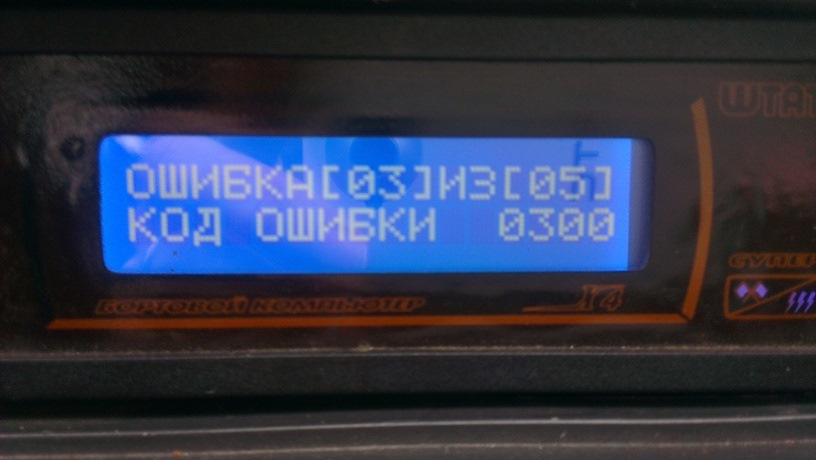
- A dangerous symptom is the occurrence of the P0300 error, which means random and multiple misfires of the fuel. In this case, you may need overhaul car. Related to it is a malfunction with code P0304, which means misfire in the fourth cylinder.
The diagnostic system based on the performance of each sensor is imperfect. Therefore, it is undesirable to look for the problem on your own.
At the service station, conclusions are drawn not only on the on-board computer, but also on the data obtained during an independent study of vehicle systems. In this case, repairs can be carried out in a shorter time frame and at lower costs.
Mismatch of problems and encoding
Sometimes error codes indicate nodes that are known to be working. This is a big problem for the owners of the VAZ-2115, so we will give examples of why this can be:
- the sensors themselves are out of order, not the units;
- low-quality fuel was poured into the tank (often leads to the occurrence of a P0300 combination);
- clogged fuel and air filters must be replaced;
- changes in the subtleties of the engine due to the use of unauthorized software for the on-board computer;
- replacement of parts for inappropriate ones;
- failure in work computer system diagnostics.
If you do not have the necessary firmware to operate LPG equipment, you will not be able to use the car at all. The computer will block it. Interesting that power unit VAZ-2115 is capable of digesting any gasoline, but its sensors are more sensitive to fuel quality. Perhaps the manufacturer was in a hurry, installing a modern system on the "fifteenth". The reviews of most motorists say exactly this.
Malfunction 1602
Most often, motorists are faced with the P1602 encoding. It means problems in the electrical circuit of transport. This error may be associated with an ECU, broken wiring, or a malfunction of the computer itself.
The vehicle health monitoring system is constantly testing battery, therefore, often on a frosty morning, the owner of a VAZ-2115 can meet an unpleasant surprise on the display in the form of an error. With her, the car simply will not start. If you often come across the P1602, then it makes sense to try to fix the problem by changing the firmware. Remember to only use the official versions.
However, the above situation, although it occurs often, is not the only reason for the appearance of the indicated code on the display. It is worth checking the car for the following problems:
- low voltage in the network (in addition, sensors can also react with errors);
- a dead battery (while the functions of the VAZ-2115 are blocked);
- short circuits in the wiring or broken wires in one of the sections of the circuit;
- increased load on the electrical circuit (happens when installing powerful speakers and a subwoofer);
- problems with the generator, in which it produces an insufficient amount of current, which leads to constant use of the battery;
- failure of the measuring sensors of the electrical network.
Often the failure of various sensors leads to the fact that when you try to start the engine, the computer issues a dozen of different codes. A failure in the operation of the on-board system itself also manifests itself. At the same time, in some cases, the car may simply not start, since errors do not just transmit information, but prevent the engine from starting.
The best way to protect against the appearance of unnecessary codes is to change the on-board electronics software. However, it is important to use only the official versions here. Poor-quality firmware can easily destroy the entire electrical system of the VAZ-2115. She can send incomprehensible commands to all controllers at once. Therefore, do not try to do this work with your own hands, it is best to trust the professionals in the event of incorrect errors. At the service station, you will be able to correctly configure the on-board computer.
How to reset an error
 If the malfunction monitoring system malfunctions, then another question arises: how to get to the station Maintenance... Of course, you can resort to the services of a tow truck, but this will have to spend additional funds. If you are 100% sure that your car is in good working order, then you can simply remove the crash records from the computer's memory. To do this, you need to take the following steps:
- Stop the engine if running.
- Switch off the ignition.
- Remove the terminals from the battery.
- After a few seconds, reconnect the battery to the network, that is, put the terminals back.
In most cases, this helps. If it is frosty outside and the car does not start due to an excessively cooled battery, then after disconnecting it, it is worth bringing the battery into heat. In this case, you will not be able to immediately use your VAZ-2115.
The listed actions will help to clear the memory of the on-board computer even after the elimination of the breakdown. After you replace the faulty unit, you will need to first try to start the car, and then follow the instructions above. As a rule, after repairs, auto mechanics immediately reset the memory of the monitoring system.
Greetings ladies and gentlemen! At least, I really want to believe that among you there are representatives of the fair sex! If you are the proud owner of a modern classic in the form of a VAZ 2114 car, then sooner or later, you will have to face errors in the ECU control system. To help understand these combinations unknown to the average driver is the main goal of this article. Errors VAZ 2114, as in many others vehicles- this is the main means for informing the driver about a malfunction of any mechanism, unit or unit of the automotive system.
Determining the malfunction on your own
Of course, we, as real drivers, always strive to solve any problem with our own hands. Well, you don’t like it when someone else’s uncle heals your "swallow" and I understand you perfectly. However, if we consider the issue of the on-board computer, then everything is somewhat different, but in certain cases you can cope on your own. I warn you right away: do not listen to pessimists who will prove with foam on their lips that you cannot defeat computer errors. But remember once and for all, the error codes will differ from the SRT options, since by and large we will test the dashboard without resorting to the help of that very bortovik. Instead of a four-digit number, we are presented with a two-digit number.
Before telling you about the different combinations, follow a few simple steps. They will help not only determine the firmware version, but also find out about the existing faults. Self-diagnosis begins with these actions!
- Find the odometer button and hold it down.
- Turn the key to position 1.
- Release the odometer (arrows will start running).
- Press the odometer again and release immediately (information about the firmware will appear).
- Repeat the previous steps again, after which, if there are obvious faults, you will see their error codes.
In the case when the lamp is on Check Engine, this means a failure in the electronics system, then you cannot do without specialists. In other cases, after carrying out these actions with the help of the following information, it will be possible to read errors. Combinations that may appear on the dashboard:
- 1 - failure of the microprocessor;
- 2 - the fuel level indicator is faulty;
- 4 - increased voltage in the electrical circuit;
- 8 - low voltage in the electrical circuit;
- 13 - there is no signal from the oxygen indicator;
- 14 - increased temperature of the coolant;
- 15 - lowered coolant temperature;
- 17 - low voltage on-board network;
- 19 - malfunction of the sensor that determines the position of the crankshaft;
- 24 - the speed sensor is out of order;
- 41 - phase sensor error;
- 51 - permanent storage device, unstable;
- 53 - CO-potentiometer is faulty;
- 61 - the lamba probe does not work correctly.
Even after eliminating the malfunction, the corresponding codes will still go to the error panel. “How can I get rid of these testimonies?” You ask. It's very simple! We turn on the ignition and disconnect the positive terminal from the battery for a few seconds.
After that, we check the result with almost 100% guarantee that if the error is corrected, the problems will disappear. Another nuance that can mislead you is the addition of errors. That is, if there are several of them, for example: 24 and 41, then you will see the number 65.
Diagnostics with special equipment
Conduct a "survey" directly on-board computer, on their own most likely it will not succeed. Of course, if you have special skills and you have a special laptop, then it is quite possible and you don’t need to tell me how to check this node. However, in most cases, you have to contact specialized services. There are so-called glitches. In other words, a situation when the information displayed by a computer does not correspond to reality. Of course, like any electronics, "bortovik" can malfunction. I hasten to reassure you - this is more an exception than a rule. If somehow it was still possible to lure the ill-fated four-digit code out of the system, although I already gave the answer to the question of how to view it. But still, consider the most important malfunctions that an on-board computer can determine:
- 0102, 0103 - the mass air flow sensor is out of order;
- 0122, 0123 - the throttle position sensor is out of order;
- 0300 - misfiring, lead to problems when starting the car;
- 0335, 0336 - failure of the knock sensor;
- 0480 - the cooling fan does not work;
- 0505-0507 - the idle speed sensor is out of order;
- 1500 - open circuit in the fuel pump chain;
- 1602 - the most popular error, means the disappearance of the power supply to the on-board network;
- 1689 - means about incorrect data coming from the on-board computer, including error codes;
- 0217 - engine overheating.
 Of course, this is only a small part of the five A4 sheets of similar codes. But I drew your attention to the most frequently encountered moments. I advise each of you to get your own table where a similar decoding is presented. I want to warn you right away, there are no injector breakdown codes in it, however, all adjacent mechanisms are under the strict control of the on-board computer. I would like to believe that with this article I achieved the tasks set and helped at least one of you. Believe me, this will be enough for me. Well, okay, something carried me away. All the best and see you soon!
Diagnostics of VAZ cars
Section 2 - "Diagnostics" consists of the following parts:
General information
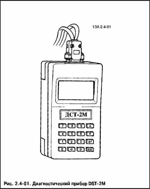
Information about the diagnostic procedure, safety precautions, and the DST-2M diagnostic tool. It also provides a description of the electrical connections of the engine control system and the purpose of the controller connector contacts.
Part "A" and diagnostic cards "A"
Provides initial information on how to perform diagnostics, including "DIAGNOSTIC CIRCUIT CHECK", diagnostic cards for the malfunction indicator, measures in case of inability to start the engine and other general cards.
Fault code maps
These cards are used if, when checking the diagnostic circuit, a malfunction code is found in the controller's memory. If there is more than one code, the analysis and elimination of faults must always start with codes P0560 (incorrect on-board voltage) or P0562 (under-voltage on the on-board network).
Part "B" Diagnostic fault cards.
In the absence of a DTC or its inconsistency, this part helps the mechanic to identify the malfunction. In these cases, the diagnosis should also begin with a diagnostic circuit check.
Part “C” and diagnostic cards “C” (cards for checking the nodes of the engine control system).
This part contains information on checking specific elements of the engine management system, as well as on their maintenance. It contains information on the elements of the fuel supply system, on the ignition system, etc.
General information
Diagnostics of the engine management system with distributed fuel injection is quite simple, provided that the order of its implementation is observed.
To carry out diagnostics, no special knowledge in the field of electronics and computer technology is required. It is enough to know the basic concepts of electrical engineering and have the skill to read simple electrical circuits... In addition, experience with a digital multimeter is required. Of course, a good understanding of the fundamentals of the engine is necessary.
The first and most important condition for the successful diagnosis of malfunctions of any system is an understanding of the principle of its operation. Before carrying out repairs, it is necessary to clearly understand how a good condition differs from a faulty one.
Acquaintance with Section 1 of the Manual "Design and Repair" is a good start to understand the operation of the system and its elements under normal conditions.
In the descriptions of diagnostics and in the diagnostic cards, certain diagnostic tools are mentioned (see Appendix 2). These diagnostic tools are used for specific purposes, and diagnostic cards describing the diagnostic procedure are based on the use of these particular tools.
When talking about diagnostic tools, it is important to remember that none of the special diagnostic tools can replace humans. The diagnostic tool and means do not perform diagnostics for a person and do not exclude the need for diagnostic maps and in describing the procedure for carrying out diagnostics.
Don't forget that there is a base engine behind the electronics. internal combustion... The performance of the engine management system depends on the health of the mechanical systems.
As a reminder, the following are a number of deviations causing malfunctions that can be mistakenly attributed to the electronic part of the engine control system:
Insufficient compression;
Air leaks;
Limiting the patency of the exhaust system;
Variation in valve timing caused by wear of parts and improper assembly;
Poor fuel quality;
Failure to comply with the terms of maintenance.
2.2 Precautions for diagnostics of VAZ cars
When working on a car, the following requirements must be observed.
1. Before dismantling the controller, disconnect the ground wire from the battery.
2. It is not allowed to start the engine without a reliable battery connection.
3. It is not allowed to disconnect the storage battery from the on-board network when the engine is running.
4. When charging, the battery must be disconnected from the on-board network.
5. It is necessary to check the reliability of the wiring harness contacts and keep the battery terminals clean.
6. Engine control harness strips are designed to mate only in a specific orientation.
With the correct orientation, the articulation is effortless. A joint with the wrong orientation can lead to failure of the block, module or other element of the system.
1. Articulation or dismemberment of the ECM elements pads with the ignition on is not allowed.
2. Before carrying out electric welding work, it is necessary to disconnect the wires from the battery and the box from the controller.
3. To avoid corrosion of contacts when cleaning the engine with a water jet under pressure, do not direct the sprayer at the system elements.
4. To eliminate errors and damage to serviceable units, it is not allowed to use control and measuring equipment that is not indicated in the diagnostic cards.
5. Perform voltage measurements using a digital voltmeter with a nominal internal resistance of more than 10 megohms.
6. If the use of a probe with a control lamp is provided, it is necessary to use a lamp of low power (up to 4 W). The use of high-power lamps, for example, from a headlight, is not allowed. If the power of the probe lamp is not known, it is necessary, by the simplest test of the lamp, to make sure that it is safe to use it to control the controller circuits.
To do this, it is necessary to connect an accurate ammeter (digital multimeter with low resistance) in series with the probe lamp and supply power from the battery to the "lamp - ammeter" circuit (Fig. 2.2-01).
If the ammeter shows a current less than 0.25 A (250 mA), the lamp is safe to use. If the ammeter shows a current of more than 0.25 A, the use of a lamp is dangerous.
7. The engine control system uses a controller with 81-pin connector, which is located in a hard-to-reach place. Since the terminals inside the connector blocks are inaccessible for connecting external measuring devices, then to check the health of the injection system harness circuits, it is necessary to use special signal splitters (Fig. 2.2-02), connected between the controller and the wiring harness.
8. Electronic devices Motor control systems are vulnerable to electrostatic discharge, so care must be taken when handling them, especially the controller.
ATTENTION. To prevent damage from electrostatic discharge, do not disassemble the metal case of the controller or touch the connector plugs.
2.1 Description of on-board diagnostics
On-board diagnostics means a software and hardware system (controller, sensors, actuators) that performs the following tasks:
1) determination and identification of errors in the functioning of the ECM and the engine, which lead to:
Exceeding the limit values for the toxicity of exhaust gases from cars, which are determined by the environmental standards currently in force in the respective country for cars;
To a decrease in engine power and torque, an increase in fuel consumption, a deterioration in the driving qualities of a car;
Failure of the engine and its components (burnout of pistons due to detonation or damage to the catalytic converter in the event of misfiring of the air-fuel mixture).
2) informing the driver about the presence of a malfunction by turning on the malfunction indicator.
3) saving information about the malfunction. At the moment of detection, the following information is entered into the controller's memory:
Fault code according to international classification (see table 2.3-01);
Status flags (signs) characterizing the malfunction at the time of the information exchange session with the DST-2M diagnostic device;
The so-called freeze frame - the values of the parameters important for the ECM at the time of the error registration.
Fault codes and related Additional Information make it much easier for specialists to find and eliminate malfunctions in the engine management system.
4) activation of emergency operation modes of the ECM. When a malfunction is detected, the system switches to emergency operation modes to prevent negative consequences (listed above). Their essence lies in the fact that in the event of failure of any sensor or its circuit, the controller uses substitute values stored in the EPROM to control the motor. In this case, the car will be able to go to the service station.
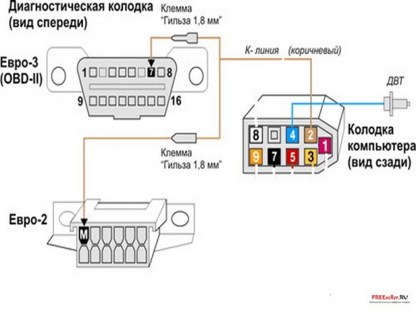
5) ensuring interaction with diagnostic equipment. The on-board diagnostics system informs about the presence of a malfunction by turning on the warning device. Then the on-board diagnostics system must provide, using special equipment, the receipt of diagnostic information stored in the controller's memory. For this, a serial information transfer channel is organized in the engine control system, which includes an ECM controller (in the role of a transceiver), a standardized block for connecting a diagnostic device (Fig. 2.3-01, 2.3-02) and a wire connecting them (K- line). In addition to the shoe, the information transfer protocol and the format of the transmitted messages are also standardized. In addition to obtaining information about the detected malfunctions and the state of the engine control system, the on-board diagnostics system allows you to perform a number of verification tests by controlling the executive mechanisms.
ATTENTION. If the car is not equipped with an immobilizer, then to diagnose the engine management system using the DST-2M device, it is necessary to connect the contacts "" 18 "and" 9 "in the block connected to the immobilizer control unit.
The main component of the OBD system is the ECM. In addition to its main task (control of the combustion processes of the fuel mixture), it carries out self-diagnostics.
When performing this function, the controller monitors the signals of various sensors and actuators of the ECM. These signals are compared with reference values stored in the controller's memory. And if any signal goes beyond the control values, then the controller evaluates this state as a malfunction (for example, the voltage at the sensor output has become zero - a short circuit to ground), generates and writes in the error memory the corresponding diagnostic information ( see above), turns on the malfunction indicator, and also switches to emergency modes ECM work.
The on-board diagnostics system begins to function from the moment the ignition is turned on and stops after the controller goes into “stand by” mode (occurs after the main relay is turned off). The moment of activation of one or another diagnostic algorithm and its operation are determined by the corresponding engine operating modes.
Diagnostic algorithms can be divided into three groups:
1) Diagnostics of sensors. The controller, monitoring the value of the sensor output signal, determines the nature of the malfunction,
2) Diagnostics of ECM actuators (driver diagnostics). The controller checks the control circuits for an open, a short to ground, or a power source.
3) Diagnostics of ECM subsystems (functional diagnostics).
In the engine management system, several subsystems can be distinguished - ignition, fuel supply, maintaining idle speed, neutralizing exhaust gases, capturing gasoline vapors, etc. Functional diagnostics gives an opinion on the quality of their work. In this case, the system no longer monitors individual sensors or actuators, but the parameters that characterize the operation of the entire subsystem as a whole. For example, the quality of the ignition subsystem can be judged by the presence of misfire in the combustion chambers of the engine. Fuel Adaptation Parameters provide information about the status of the fuel delivery subsystem. Each of the subsystems has its own requirements for the value of the maximum permissible deviations of its parameters from the average values.

Fault indicator
The malfunction indicator for VAZ-11183, 21101 cars is located in the instrument cluster.
Turning on the indicator signals to the driver that the on-board diagnostic system has detected a malfunction of the ECM and the further movement of the car occurs in emergency mode. In this case, the driver is obliged to place the car at the disposal of the maintenance specialists as soon as possible.
Blinking of the warning lamp indicates the presence of a malfunction that can lead to serious damage to the ECM elements (for example, misfires can damage the catalytic converter).
When the ignition is turned on, the indicator should light up - thus the ECM checks the serviceability of the lamp and the control circuit. After starting the engine, the indicator should go out if there are no conditions in the controller's memory for turning it on.
To protect against accidental, short-term errors that may be caused by loss of contact in electrical connectors or unstable work engine, the indicator turns on after a certain time interval after the ECM malfunction is detected. During this period, the on-board diagnostic system checks for a malfunction.
After eliminating the causes of the malfunction, the indicator will be turned off after a certain delay time, during which the malfunction does not manifest itself, and provided that there are no other trouble codes in the controller's memory that require the alarm to be turned on.
When clearing (deleting) the fault codes from the controller memory using the diagnostic equipment, the signaling device goes out.
The procedure for diagnosing VAZ cars
Everything diagnostic work should always start with "Diagnostic Circuit Check"
The Diagnostic Circuit Check provides an initial check of the system and then refers the mechanic to other manual cards. It should be the starting point of all work.
The entire manual is structured according to a single scheme, in accordance with which checking the diagnostic circuit sends the mechanic to certain cards, and those, in turn, can refer to others.
It is necessary to strictly adhere to the sequence indicated in the diagnostic cards. Violation of the sequence of diagnostics can lead to incorrect conclusions and replacement of serviceable components.
The diagnostic cards are based on the use of the DST-2M diagnostic device. It provides the mechanic with information about what is happening in the engine control system.
The DST-2M is used to monitor the ECM. The DST-2M device reads and displays the information transmitted by the controller to the diagnostic block.
Diagnostic circuit check
After inspecting the engine compartment, the first step in the entire diagnosis or search for the cause of non-compliance with toxicity standards is to check the diagnostic chain described in section 2.7A.
The correct procedure for diagnosing a malfunction involves the following three basic steps:
1. Checking the performance of the on-board diagnostic system. Verification is carried out by performing the Diagnostic Circuit Check. Since this check is the starting point for diagnostics or searching for the cause of non-compliance with toxicity standards, you must always start with it.
If the on-board diagnostics does not work, the diagnostic circuit check displays a specific diagnostic card. If the OBD is working properly, go to step 2.
2. Checking for the presence of up-to-date fault codes. If there are actual codes in the controller's memory, it is necessary to refer directly to the diagnostic cards with the corresponding numbers. If there are no codes, go to step 3.
3. Control of the data transmitted by the controller. To do this, you need to read the information using the DST-2M device.
The description of the device and the parameters displayed by it are given below. Typical parameter values for specific operating conditions are given in Table 2.4-01.
Error codes of malfunctions of cars VAZ 2110, VAZ 2112, VAZ 2114, 2115, Lada viburnum Priora you can find
Diagnostic cards of VAZ cars
Several faults often found on cars of the 2115 family.
Cooling system
In the event of a malfunction in the cooling system, we drive off the road and stop the engine.
We open the hood and carefully examine the engine compartment. If steam escapes, we determine a specific place. We inspect the engine, check the expansion tank for the position of the coolant level. For one thing, we determine the state of the thermostat, radiator, rubber hoses in the engine cooling system.
Do not unscrew the plug immediately after stopping the engine. expansion tank... In the cooling system, the liquid is under high pressure. When we unscrew the plug, the pressure drops sharply, and according to the laws of physics, the coolant boils. Naturally, its splashes can cause burns to hands and face. If there is an urgent need to unscrew the expansion tank cap on an engine that has not yet cooled down, put some thick cloth on top and only then slowly unscrew the cap.
We are not too lazy to look under the instrument panel of the VAZ-2115. Under it, coolant drips may be found oozing from the heater or radiator tap.
If coolant leaks are caused by a burst hose, it can be temporarily patched with adhesive tape (electrical tape, scotch tape).
Much more problems if the leak comes from a heater, radiator or thermostat. It is difficult to eliminate it on the way. In this situation, it is recommended to add water to the cooling system and monitor the temperature readings while driving. If necessary, the level in the cooling system will have to be restored periodically. Please note that if you use water instead of antifreeze for a long time, this will most likely provoke the formation of scale in the VAZ-2115 cooling system. As a result, cooling will deteriorate, and the service life will decrease. Therefore, after an emergency trip, be sure to fix the leak, drain the liquid diluted with water, flush the system and refill with fresh coolant. The most important condition is that it is forbidden to add cold water to an overheated engine! The engine should cool down for at least half an hour with the hood open.
If the cooling system of the VAZ 2115 is faulty, and there is no coolant leakage, we check the integrity of the fuse No. 5 (at 20A). It performs the function of forced protection of the on-board power supply circuit in the electric fan of the cooling system. There is a fuse in mounting block located in the engine compartment. If the electric motor starts working after replacing the fuse, the journey can be continued.
If the electric motor does not work after replacing the fuse, we will carry out additional diagnostics. Let's take two additional wires and supply power to the electric motor directly from the battery.
Please note that the wires must be insulated and securely fastened. Shorts of wires between each other must not be allowed! Be sure to pay attention to the polarity of the connection: the electric motor must rotate in such a way that the fan blows air to the engine through the radiator, and the directions of the incoming (travel) air flow and the air flow generated by the fan coincide.
If the electric motor starts working after these manipulations, then the wiring of the cooling system or the fan relay is faulty. The relay is located under the cover on the right side of the console dashboard VAZ 2115. If the engine is deaf, a malfunction of the electric motor itself or the wiring is possible. Unfortunately, neither the electric motor nor the relay can be repaired and will require replacement.
The engine can also overheat if the thermostat fails. This unit regulates the flow of fluid through the cooling system either bypassing the radiator (to speed up the warm-up of a cold engine), or through the radiator. It is not difficult to check the thermostat: on a warm engine, we probe the lower hose connecting the radiator and the engine. If the hose is cold, the thermostat is most likely defective, so no coolant circulates through the radiator.
Brake system
Possible malfunctions of brake systems and ways to eliminate them
Cause of malfunction
Remedy
Increased brake pedal travel
Air in the hydraulic drive system
Bleed the system
The thrust ring of the rear wheel cylinder piston has lost its elasticity and under the action of the tightening spring of the brake pads together with the piston is displaced inside the cylinder
Replace the wheel cylinder assembly
Leakage violation brake system(fluid flow)
Locate the fluid leak and replace the parts affecting the leak. If there are leaks in the pipe connections, tighten the connections or replace the gaskets
Increased clearance between the head of the adjusting bolt vacuum booster and the master cylinder piston
Cm.<Вакуумный усилитель>
The brake pedal moves down slowly with constant force on it and the parking brake applied
Damage to the cuff 14 (see Fig.8.3)
Replace damaged cuff
Brakes on all wheels or axles do not fully release (suspended wheels rotate tightly)
No clearance between the head of the adjusting bolt of the vacuum booster and the piston of the master cylinder
Cm.<Вакуумный усилитель>
Incomplete return of the brake pedal after braking due to incorrect installation of the brake signal switch
Set the gap (8 + 1) mm (see Fig. 7.16) between the plastic tip of the brake light switch and the emphasis on the pedals
Clogged expansion holes in the main brake cylinder or the overlap of the expansion holes with the edges of the cuffs 14 (see Fig. 8.3)
Remove the master cylinder reservoir and connecting sleeves 3 (see Fig. 8.3). Clean the expansion holes with a soft wire 0.6 mm in diameter. If at the same time the wire rests on the cuff, then it is necessary to disassemble master cylinder and replace swollen cuffs 14
One brake mechanism does not release (the suspended wheel rotates tightly)
Jammed guide pins in the base of the front bracket
Replace or lubricate guide pins. Replace damaged finger covers (see.<Замена направляющих пальцев>)
Seizure of pistons in the caliper housing
Remove the brake caliper housing from the base, remove dirt and traces of corrosion from the surface of the housing cylinder and lubricate the working surfaces with NG-213 liquid or castor oil (see.<Ремонт тормозного механизма переднего колеса>)
Loss of elasticity of the O-ring of the brake caliper housing
Remove the caliper housing from the base and replace the O-ring (see.<Ремонт тормозного механизма переднего колеса>)
Pads seized due to heavily soiled base guide groove
Remove the pads and clean the guide groove and ledges of the base from corrosion and dirt (see.<Замена колодок тормозных механизмов передних колес>)
Weakening or breakage of the return spring of the rear brake pads
Replace spring
Seizure of the rear brake pistons due to dirt or corrosion
Disassemble the wheel cylinder, clean the parts from dirt and corrosion, rinse, replace the mud covers
Swelling of the rear wheel cylinder piston o-rings
Replace O-rings and brake fluid
No clearance between the brake pad and the rear brake drum due to improper installation thrust ring automatic adjustment
Dismantle the wheel cylinder, eliminate the skew of the thrust ring
Car skidding or sideways when braking
Unequal tire pressure
Bring the tire pressure to normal
Oiling of friction linings in one of the brake mechanisms
Replace the pads or wash the pads with gasoline, followed by sanding with a fine sandpaper and thoroughly removing the abrasive dust from the pad
Seizure or deep scratches on the surface of the brake disc or drum
Repair or replace disc or brake drum assembly with hub
Flow brake fluid in one of the front brakes or wheel cylinders
Eliminate the leak
The rear wheels are locked earlier than the front ones due to a malfunction of the pressure regulator or improper adjustment of its drive
Adjust or replace the pressure regulator (see.<Регулировка регулятора давления>)
Insufficient braking performance (increased effort on the brake pedal)
Worn or oily brake linings
Replace or flush brake pads
Incomplete adhesion of the linings to the drum in the rear brakes
Clean out protruding places at the linings. Replace pads if necessary
Leakage in the vacuum hose connection
Restore the tightness of the connection
The filter 14 (see Fig.8.2) of the vacuum brake booster is dirty
Rinse the filter or replace with a new one
Torn diaphragm 7 or 8 (see Fig.8.2) of the vacuum brake booster
Replace the diaphragm
Sealing cuffs 13 (see Fig. 8.2) of the vacuum brake booster do not provide tightness
Replace the seals and clean the cylindrical working surfaces of the valve body and connector
Leakage in the connection of the cover 6 (see Fig. 8.2) with the housing 11 of the vacuum amplifier
Restore tightness
Leakage in the connection of the vacuum booster with the main cylinder body
Replace O-ring 12 (see Fig.8.2)
Failure of the vacuum booster as a result of the ingress of brake fluid into the cavity of the vacuum booster
Replace the master cylinder seals, remove fluid from the amplifier and replace the diaphragm
Rattling in the brakes
Ovality or beating of the working surface of the brake drums of the rear wheels
To bore out brake drums assembled with a hub or replace with new ones
Broken disc brake pad springs
Replace brake pads (see.<Замена колодок тормозных механизмов передних колес>)
Front wheel brake pins worn
Replace guide pins (see.
Worn holes for guide pins in the base of the brake caliper
Replace base
It takes a lot of grip force to hold the car parking brake
Jamming of the cables in the guiding sheaths
Disconnect the cables, clean the dirt, lubricate the cables and their connections with grease<Лига>
Rear brake linings oiled
Flush pads or replace pads with pads
Parking brake incorrectly adjusted
<Регулировка привода стояночного тормоза>)
Long travel of the parking brake lever handle
Large free play of the expander link of the parking brake drive in the rear wheel brakes
Adjust the parking brake drive (see.<Регулировка привода стояночного тормоза)
Heating of brake drums when driving without braking
Incorrect adjustment of the expander link of the parking brake drive
Adjust the parking brake actuator
Reduced level of brake fluid in the reservoir of the master brake cylinder in the absence of an external leak in the hydraulic drive
Wear or swelling of the outer cuff 8 (see Fig. 8.3) of the main brake cylinder
Remove the brake master cylinder and replace the oil seal. Drain the brake fluid from the cover 6 (see Fig. 8.2) of the vacuum booster
Clutches
Possible clutch malfunctions, their causes and remedies:
Cause of malfunction
Remedy
Incomplete clutch disengagement (clutch "leads")
Insufficient full travel of the clutch pedal
Adjust the clutch release drive
Warping of the driven disc (face runout more than 0.5 mm)
Straighten or replace the disc
Sticking of the driven disc hub on the splines of the input shaft
Clean the slots, rinse with white spirit. If the splines are worn, replace the input shaft or driven disc
Skewed or warped pressure plate
Replace clutch cover with pressure plate and spring
Loose rivets or breakage of the clutch disc friction linings
Replace linings, check disc face runout
Violation of the clutch cable
Replace the cable
Incomplete clutch engagement (clutch "slips")
Increased wear or burning of the friction linings of the driven disc
Replace friction pads or clutch plate assembly
Damaged or seized clutch actuator
Jerks during clutch operation
Oiling of the clutch disc friction linings, flywheel surfaces and pressure disc
Thoroughly flush oily surfaces with white spirit, replace worn or damaged gearbox and engine oil seals. Check for oil leaks through the flywheel mounting bolts; if there is a leak, install the bolts on the sealant, as indicated in the subsection "Assembling the engine"
Sticking in the clutch release drive
Eliminate the causes of seizure. Replace damaged parts
Surface damage or warpage of the pressure plate
Replace clutch cover assembly with pressure plate
Increased noise when engaging the clutch
Breakage of the damper springs of the driven disc
Replace driven disc assembly
Increased noise when disengaging the clutch
Wear, damage, leakage of grease from the clutch release bearing
Replace bearing
Ignition module
There are several typical signs that directly indicate problems with the ignition module:
1. Idling of the engine floats.
2. The engine thrust periodically disappears for no reason.
3. The car accelerates very slowly when accelerating.
4. The cylinders stop working in pairs.
Note that the same signs indicate a malfunction of the BB type wires and the vehicle's ignition system plugs, so at the beginning, you should check them, and if everything is in order with them, then replace the ignition module.
Fuel pump
- the car will not start
A possible reason may be a non-working or semi-working gas pump. The fuel pump must create a certain pressure in the fuel system for normal operation. But the cause of the malfunction can be not only the fuel pump, in any case, the first thing to do is to measure the pressure in the fuel rail, check the spark and draw the appropriate conclusions. More information can be found here.
- the fuel pump does not "buzz" after turning the ignition key
Here, most likely, the matter is already covered in the wiring to the gas pump. A separate article is devoted to this problem.
- interruptions in engine operation
- the car jerks at low speed
Again, the fuel pump itself may be in order, here a small filter (mesh) under the fuel pump may already be a problem.
Starter
1. Slipping of the freewheel clutch Generator
Relay-regulator
Call an assistant to check the regulator. It is necessary for him to start the engine, bringing the speed to 3000. At the same time, turn on the dimensions of the high beam, the rear window heater and the stove. Measure the voltage on the battery with a tester, the value of which must be more than 13.2 V (for generator 9402.3701), or 13.6 V (for generator 37.3701).
If the voltage is much lower than this value, this may be due to a malfunction of the generator windings (open circuit, short circuit), a relay regulator, or a lack of contact due to oxidation on the rings of the excitation winding.
Indirectly, a malfunction of the relay-regulator can be determined if the main beam is turned on, turning off the rest of the consumers. For this purpose, a voltage measurement should be made, the indicators of which should be 13.2 or 13.6 V.
A more reliable way to determine the operability of the regulator with the removed generator or relay-regulator. You will need a 12V test lamp, which should be connected between the brushes. Next, you should simultaneously apply a direct current with a voltage of 12 V from the power supply that fits to it, by connecting the plus to the "D +" terminal, and the minus to the car ground.
After this, the lamp should light up. If the voltage is gradually increased to 16 V, it should go out. Otherwise, the regulator will need to be replaced. If the brand of your generator is 37.3701, connect plus from a source with constant voltage to contacts "B" and "B", minus to ground.
Generator valves (rectifier unit)
To check it, you just need to use a battery and a control lamp. You need to connect the plus of the battery with a control lamp to the generator contact "B +" (for the generator 37.3701, to the "30" contact), and the minus to the case. If the lamp is on, then there is a short circuit or a breakdown in the valve block (positive and negative).
To make sure that the positive valve block is working properly, make a connection using a battery plus indicator lamp to contacts ("B" or "30"), and a minus one to any phase winding. If the light comes on, then one of the valves is broken.
How to check the VAZ 2115 generator It is possible to check the negative valves (diodes) by connecting any phase winding with ground (generator case) through the lamp. If the lamp is on, it means that there is a short circuit in the generator case with the stator winding or one of the valves is broken. You can use (ohmmeter) for testing, but for this you need to disconnect any diode contact.
It is better to replace the rectifier unit assembled and in a car workshop.
Pump
The water pump plays an important role in the life of the engine. Thanks to the pump, the coolant (coolant) can freely circulate through the cooling system, thus removing the temperature from the heating parts of the engine. A faulty water pump can overheat the engine and completely destroy it. In order to prevent this, it is necessary to monitor the condition of the pump and its performance. A faulty water pump makes itself felt by the following symptoms: Leakage in the gland area.
Humming while running. Poor coolant circulation. Rise in engine temperature.
Falling coolant level. To make sure your pump is defective, run a few simple tests: Warm up the motor to operating temperature, then squeeze the upper hose. If at the same time you feel that the fluid in the system continues to circulate, you can conclude that the water pump is working. Listen to if the pump is humming, if you feel a hum, it is most likely dying. It is better not to wait for this to happen and replace the pump in order to avoid big trouble.
I recently replaced the pump as it was out of order, as I understood from the howling sounds. Today I want to tell you about how to replace the VAZ 2110 water pump with your own hands without removing the generator drive. 1. First of all, I decided to remove the adsorber for the convenience of doing the work, without disconnecting the wires and hoses.
2. Next, you need to remove the plastic cover from the engine, as well as the timing belt cover. 3. Now take a jack and jack up the right side of the car, your task is to hang out the front right wheel. This is done in order to expose everything according to the labels.
For convenience, I decided to make one mark with white paint, in the future, believe me, it came in handy. 4. As much as I would not like, but the wheel still had to be removed, since K.
Access to the bottom bolt of the plastic casing was needed. 5. In excellent condition, so there is no point in changing it.
In addition, I decided to try to replace the pump without removing the alternator drive belt. As it turned out later, it was a good idea and saved a lot of time. 6. However, the plastic casing, and with it the pulleys with the camshaft rollers, still had to be removed. To do this, it is necessary to loosen the tension rollers, then remove the timing belt from them. 7.
Next, you need to lock the camshaft gears with something flat in order to unscrew them. Be careful, the teeth are quite soft. 8. When the pulleys are dismantled, you need to unscrew the actual plastic casing itself.
The unpleasant moment is that one mounting bolt will need to be unscrewed in the position from the bottom, through the space near the wheel. Now we can say that we got to the pump. 9. The water pump VAZ 2110 is fastened with three mounting bolts for a hexagon. Unscrew them, then slightly tapping on its body, try to pull it out.
10. Place a container for the coolant and be careful not to splash. 11. Take a new VAZ 2110 pump and make sure that there is a sufficient amount of lubricant in it. I also recommend applying a thin coat of sealant if you have a paper gasket. Let it dry.
The assembly is traditionally carried out in the reverse order. Replace the water pump. Install the plastic cover. Secure the camshaft pulleys in their places. Put on the timing belt. Align and put on the timing belt according to the previously applied marks on the camshaft.
Turn the engine with the wheel, correct the correct tension and position of the belt. When everything is installed, add antifreeze (or any other coolant), and you can check the operation. Replacing the water pump took 3 hours of my time, everything works fine, the malfunction is fixed.
The presence of an on-board computer on the car allows you to identify malfunctions in time, take appropriate measures before the breakdown becomes serious and expensive to fix.
The main thing here is to be able to correctly read error codes when diagnosing a VAZ 2114... Not everyone understands what exactly the car is pointing at when giving out certain designations. Therefore, today we will try to tell you about the most common error codes, and note what each of them means.
Self-diagnosis
Immediately, we note that the result of diagnostics with your own hands in the conditions of your own garage and at specialized car services is somewhat different. Service stations have at their disposal all the necessary equipment, with the help of which the maximum number of error codes from the on-board computer of your car is calculated.
Self-diagnosis with your own hands will allow you to achieve a certain positive result. But alas, it is extremely rare to find all errors.
The nuances of self-diagnosis
The indications for self-diagnosis and referral to specialized service stations will be different, error codes are also displayed differently. Therefore, we will consider two options today.
It is not at all necessary to use an on-board computer to diagnose problems with the operation of the machine. Not all owners of the VAZ 2114 know about this method, so we will definitely tell you about it.
It consists in the following actions.
- Sit in the driver's seat and hold down the odometer button.
- Then turn the ignition key to the first position.
- Release the odometer button. After that, the arrows will start running.
- Once again, hold down the button and unplug. This will allow you to see which version of the firmware is being used in your case.
- Press and release the button a third time. So you will see codes indicating the presence of certain errors in the operation of the car.
Since this is not a specialized equipment, the codes will be presented in this case in the form of two-digit designations, not four-digit ones.
Let us now consider the most popular errors that occur during such diagnostics, and figure out what the code means. Even without an on-board computer, you can detect malfunctions on the VAZ 2114 by odometer codes.
We suggest that you familiarize yourself with them according to the table.
| Code | Description |
| 1 | Microprocessor problems |
| 2 | There is a problem in the fuel tank gauge sensor circuit. |
| 4 | The mains voltage is too high |
| 8 | Voltage too low |
| 13 | There is no signal from the oxygen sensor |
| 14 | The signal level of the coolant temperature sensor is very high |
| 15 | The signal level of the coolant temperature sensor is very low |
| 16 | Too high voltage is present in the on-board network |
| 17 | Very low voltage in the on-board network |
| 19 | Incorrect signal coming from the crankshaft position sensor |
| 24 | Defective vehicle speed sensor |
| 41 | Phase sensor is sending wrong signals |
| 51 | Read-only memory problems detected |
| 52 | Problems detected in the operation of the random access memory |
| 53 | CO potentiometer does not work |
| 61 | Lambda probe sensor does not work |
It is important to take into account the fact that mistakes can add up. For example, if your car has faults indicated by codes 4 and 1, the odometer will show the number 5.
Plus, all trouble codes will be stored in memory until you manually reset them yourself. To do this, disconnect the terminals from the battery, while keeping the ignition on, wait a few seconds and connect it back. Do not forget to do this, especially if you are going to go to a service station for diagnostics. They will find these errors and will fix them, although in fact you have already done everything yourself. Paying extra money? No, not worth it.
On-board computer codes and their meaning
Now let's talk about common error codes that can be identified by diagnosing the on-board computer of your VAZ 2114. It should be borne in mind that we are talking about electronics, which can also sometimes work incorrectly. But, as practice shows, in the vast majority of cases, the error codes on the on-board computer correspond to real problems on the car.
It takes an incredibly long time to study each error. Therefore, in this table we have collected the most common, with which the owners of the VAZ 2114 meet regularly.
| Codes | Description of the problem |
| 0102, 0103 | Incorrect signal level of the MAF sensor. |
| 0112, 0113 | Incorrect intake air temperature sensor signal. It needs to be replaced |
| 0115 - 0118 | Incorrect coolant temperature sensor signal. It needs to be replaced |
| 0122, 0123 | Interference or incorrect signal from the throttle position control sensor. It is recommended to replace the sensor |
| 0130, 0131 | Oxygen sensor does not work |
| 0135 - 0138 | The oxygen sensor heating device does not work. Replacement required |
| 0030 | A breakdown in operation or an open in the control circuit of the oxygen sensor heater to the neutralizer was recorded. |
| 0201 - 0204 | Open circuit detected in injector control circuit |
| 0300 | Random or persistent misfire detected. The car may not start right away |
| 0301 - 0304 | Misfire detected in engine cylinders |
| 0325 | Malfunction occurred in the detonation device circuit |
| 0327, 0328 | The knock sensor is out of order. It needs to be replaced |
| 0335, 0336 | Crankshaft position sensor malfunction detected. Device needs to be replaced |
| 0342, 0343 | The phase sensor is out of order. Device needs replacement |
| 0422 | Neutralizer defective |
| 0443 - 0445 | The canister purge valve does not work. Device replacement required |
| 0480 | The cooling fan is not working. Device replacement required |
| 0500, 0501 , 0503, 0504 | The speed sensor is out of order. The device needs to be replaced |
| 0505 - 0507 | The idle speed control malfunctions that affect the number of revolutions (lower or higher). The detection of such an error indicates the need to replace the regulator. |
| 0560, 0562, 0563 | Mains voltage failures are observed. A more thorough diagnostics is needed, which will identify the exact sections in the chain required for replacement. |
| 0607 | Knock channel does not work |
| 1115 | The oxygen sensor heating circuit is intermittent |
| 1135 | An open circuit was noticed in the heating circuit of the oxygen sensor, possibly a short circuit. The sensor needs to be replaced |
| 1171, 1172 | Potentiometer gas level is abnormal |
| 1500 | An open circuit is detected in the control circuit of the fuel pump device |
| 1509 | The idle element control circuit is overloaded. |
| 1513, 1514 | The on-board computer detected an open circuit in the idle device circuit. |
| 1541 | There was an open in the fuel pump relay control circuit |
| 1570 | Traction control received an open circuit |
| 1600 | Traction control data does not come to the on-board computer |
| 1602 | It is one of the most common codes when diagnosing a BC for malfunctions. Means the loss of voltage of the on-board network on the electronic control unit |
| 1606, 1616, 1617 | Breakage of the sensor for detecting uneven road surface is detected |
| 1612 | Electronic control unit reset malfunction detected |
| 1620 | Permanent storage problems |
| 1621 | Breakdown of random access memory. |
| 1689 | In the event that this combination of numbers appeared during the diagnosis, the on-board computer may show incorrect error codes. |
| 0337, 0338 | Errors in the functioning of the crankshaft position control element or an open circuit. |
| 0481 | The second cooling fan has broken. The device needs to be replaced |
| 0615 - 0617 | An open or short circuit detected in the starter relay circuit |
| 1141 | The heating device of the first oxygen sensor after the neutralizer is out of order |
| 230 | The fuel pump relay is out of order and cannot be repaired. The device needs to be replaced soon |
| 263, 266, 269, 272 | These codes indicate a breakdown of the driver of the first, second, third or fourth injectors - the elements need to be replaced. |
| 640 | This combination indicates an open circuit in the CheckEngine lamp circuit |