The gas distribution mechanism (timing) serves to ensure the timely supply of air or a combustible mixture to the engine cylinders (depending on the type of engine) and the release of exhaust gases from the cylinders. Let's figure out why it is necessary to change the timing of the timing.
All engine operating modes have their own optimal values by the duration of the opening and closing of the valves. Thanks to automatic control The gas distribution mechanism can increase power and torque in almost all engine operating modes and reduce the toxicity of exhaust gases without the use of other design solutions.
Thus, the variable valve timing system serves to optimize them when the engine is idling, maximum power and maximum torque and to ensure exhaust gas recirculation.
On modern cars an automatic timing changeover system is used, as well as a cylinder shutdown system to reduce fuel consumption and reduce toxicity in the mode of partial engine load. Let's consider the main types of such systems.
Methods for changing the valve timing can be classified according to the adjustable parameters of the timing:
- turning the camshaft;
- the use of cams with different profiles;
- change in valve lift.
The most common system that changes the phases by turning the camshaft, which is used on cars of the following brands:
- BMW: VANOS (Double VANOS);
- Toyota: VVT-i (Dual VVT-i), Variable Valve Timing with intelligence;
- Volkswagen: VVT, Variable Valve Timing;
- Honda: VTC, Variable Timing Control;
- Hyundai, KIA, Volvo, General Motors: CVVT, Continuous Variable Valve Timing;
- Renault: VCP, Variable Cam Phases.
Using the example of VAG cars (Volkswagen Audi Group), we can consider the common VVT timing system with hydraulically controlled couplings located one on each camshaft of the engine.
Couplings are hydraulic devices connected to the engine's lubrication system. Controlled by the engine control unit based on the speed data crankshaft, load, temperature and other parameters. Oil from the engine lubrication system enters through the channels in the valve timing housing and in the camshafts to the hydraulic clutches, which rotate the camshafts in accordance with the commands of the control unit.

There are also systems for changing the timing of the timing, the operation of which is based on the use of cams of various shapes, due to which a stepwise change in the duration of the opening and the height of the valve lift is achieved. Such systems are used on the following vehicles:
- Honda: VTEC, Variable Valve Timing and Lift Electronic Control;
- Toyota: VVTL-i, Variable Valve Timing and Lift with intelligence;
- Mitsubishi: MIVEC, Mitsubishi Innovative Valve Timing Electronic Control;
- Audi: Valvelift System.
These systems are basically similar in design and principle of operation, which can be seen on the example of VTEC.
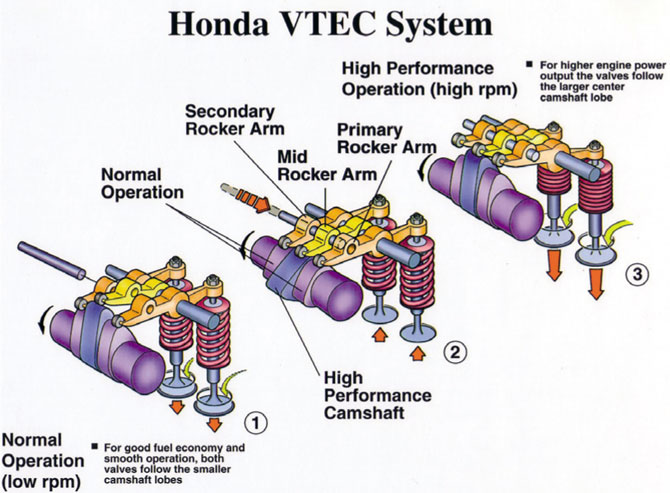
The camshaft has two small and one large cams for every two valves. In the mode of engine operation with a low crankshaft speed, the small cams through the engine with a low crankshaft speed, the small cams act on a pair of intake valves through the corresponding rockers. The large cam moves the free rocker arm. The valves have a minimum lift, the timing phases are characterized by a short duration.
Control system with a locking mechanism with hydraulic drive, provides stepwise switching from one operation mode to another when the engine crankshaft reaches a certain speed. The rockers of the small and large cams are connected with a locking pin and then the force is transferred to the intake valves from the large cam of the camshaft. Thus, valve travel and valve timing are increased.
The disadvantages of such a system are the stepwise transition from one mode to another and the structural complexity of the implementation of the blocking process.

The most advanced design of the timing system at the moment is based on adjusting the valve lift. The pioneer in this direction is BMW, which proposed the development of Valvetronic. A similar principle is implemented in other systems:
- Toyota: Valvematic;
- Nissan: VEL, Variable Valve Event and Lift System;
- FIAT: MultiAir;
- Peugeot: VTI, Variable Valve and Timing Injection.
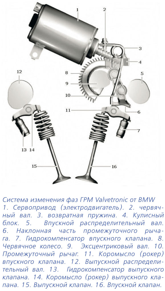
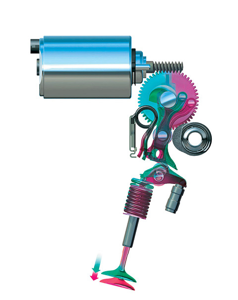
The Valvetronic system is only installed on the intake valves. The valve travel is changed using a complex kinematic diagram. The eccentric shaft 9 is driven by the electric motor 1 through the worm gear 2. The rotation of the eccentric shaft 9 changes the position of the intermediate lever 10, which, in turn, sets a certain movement of the rocker arm 11 and the corresponding movement of the valve 16. The change in the valve lift is carried out continuously depending on from engine operating modes. Such a system allows you to refuse to use throttle in some engine operating modes.
The timing system is reliable and usually does not cause trouble for car owners. But strict requirements are imposed on quality and service life. engine oil, since the drive control is hydraulic. No impurities, foreign particles are allowed, the requirements for viscosity and oil change regulations must be strictly observed.
Let's talk about some of the known faults in the timing system. For example, by car Renault Megane III (release after 2008, 1.6 liter K4M / F4R 830 engine) knocking can often be heard from the top of the engine after a cold start. The most common cause of this ailment lies in the drive of the timing system, namely in the intake camshaft coupling. To eliminate the malfunction, it is required to replace the drive of the phase change system and a mandatory software update for the electronic engine control unit.
On the Mazda CX-7 car (released after 2007 with a 2.3-liter L3 Turbo engine), a similar malfunction occurs: excessive noise from the drive of the timing system, especially when starting a cold engine. The main reason is the incomplete inclusion of the locking pin of the drive of the variable valve timing system. The procedure for eliminating the breakdown is as follows:
- Install a modified variable valve timing system drive.
- Change engine oil.
- Start the engine, let it run for Idling at least 5 minutes.
- Verify fuel pump high pressure for leaks.
- Switch off ignition.
- Wait until the coolant temperature drops.
- Change engine oil and oil filter.
Have KIA car Rio (2005-2011, 1.6 liter G4ED engine) sometimes unpleasant problems occur: erratic idle, deterioration performance characteristics engine. The reason is similar: a malfunction of the drive of the timing system, namely the exhaust camshaft clutch. The remedy is as follows:
- Check the operation of the timing system drive.
- Check the resistance of the camshaft drive. Nominal impedance: 6.7-7.9 ohms.
- Replace if necessary.
The common name for the variable valve timing system is Variable Valve Timing.
Why is she needed
With its help, the operating parameters are adjusted for various operating modes of the engine. This increases engine torque and power, saves fuel and reduces harmful emissions.
It is necessary to adjust the following parameters of the gas distribution mechanism:
- the moment of opening and closing the valves;
- the duration of their opening:
- valve lift.
The combination of these parameters is the valve timing, expressed in the duration of the intake and exhaust strokes, which is characterized by the angle of rotation of the crankshaft relative to the "dead" point. The valve timing is influenced by the shape of the camshaft cam, which acts on the valve.
The magnitude of the phases must be adjusted for different operating modes of the engine. At low revs, they should be minimal ("narrow" phases). On the contrary, for high revs of the engine, the valve timing is as wide as possible, but at the same time they must completely overlap the intake and exhaust strokes (natural exhaust gas recirculation).
But the camshaft cam has a shape that at the same time cannot provide maximum parameters narrow and wide valve timing. Therefore, in practice, a cam shape has been made that provides a compromise between high power at high rpm and high power at low rpm of the crankshaft. It is for the optimal resolution of this contradiction that a system for changing the valve timing has been created.
There are several ways of variable phases, which depend on the controlled parameters of the gas distribution mechanism. They are characterized by:
- by turning the camshaft;
- using cams with different profiles:
- by changing the valve lift.
Among the systems for changing the valve timing, the most widespread are systems that use a camshaft rotation. The most famous are the following:
- VANOS (Double VANOS) from BMW;
- VTC, Variable Timing Control from Honda;
- VVT-i (Dual VVT-i), Variable Valve Timing with intelligence from Toyota;
- CVVT, Continuous Variable Valve Timing, installed on General Motors vehicles; Volvo, Hyundai and Kia;
- VVT, Variable Valve Timing from Volkswagen;
- VCP, Variable Cam Phases used on Renault vehicles.
All of these systems work on the principle of camshaft rotation in the direction of rotation. This achieves the opening of the valves earlier than their initial position.
Gas distribution systems of this type have common system control and hydraulically operated clutch (phase shifter).
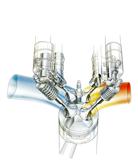
Automatic variable valve timing system:
1 - Hall sensor of the intake camshaft; 2 - hydraulically controlled intake shaft clutch (phase shifter); 3 - intake camshaft; 4 - Hall sensor of the exhaust camshaft; 5 - hydraulically controlled exhaust shaft coupling (phase shifter); 6 - the exhaust camshaft; 7 - electrohydraulic distributor of the intake shaft (solenoid valve); 8 - electro-hydraulic distributor of the exhaust shaft (solenoid valve); 9 - engine control unit; 10 - signal from the coolant temperature sensor; 11 - signal from the air flow meter; 12 - signal from the engine crankshaft speed sensor; 13 - oil pump.
Hydraulic clutch
This clutch is used to rotate the camshaft and consists of a rotor and a housing, which is the camshaft drive pulley. The cavities between the housing and the rotor are filled with engine oil, which ensures free rotation of the rotor relative to the housing and, accordingly, the rotation of the camshaft by the required angle.
In almost all types of gas distribution systems, a hydraulically controlled clutch is installed on the intake camshaft. To expand the control parameters, on some designs, couplings are installed on the intake and exhaust camshafts.
Control system
A control system is used to automatically regulate the operation of the hydraulically operated clutch. It consists of an electronic control unit, input sensors and an actuator. For the operation of the control system, Hall sensors are used, which assess the position camshafts... Other sensors are also used that measure:
- crankshaft rotation frequency;
- air flow;
- temperature.
The sensors transmit signals to the control unit, which controls the actuator - an electro-hydraulic distributor in the form of a solenoid valve. Its task is to provide the supply of engine oil to the hydraulically controlled clutch and to drain it from the clutch in accordance with the engine operating mode.
The following operating modes of the variable valve timing system are applied:
- idle (at minimum crankshaft speed);
- maximum power;
- maximum torque.
In another type of variable valve timing systems, cams of various shapes are used. As a result, the opening times and the lift of the valves are changed in steps. The following known systems of this type are noted:
- VVTL-i, Variable Valve Timing and Lift with intelligence from Toyota;
- VTEC, Variable Valve Timing and Lift Electronic Control from Honda;
- Valvelift System from Audi;
- MIVEC, Mitsubishi Innovative Valve timing Electronic Control from Mitsubishi.
With the exception of the Valvelift System, these systems are basically similar in design and operation.
Let's consider the principle of operation using the example of the VTEC system.

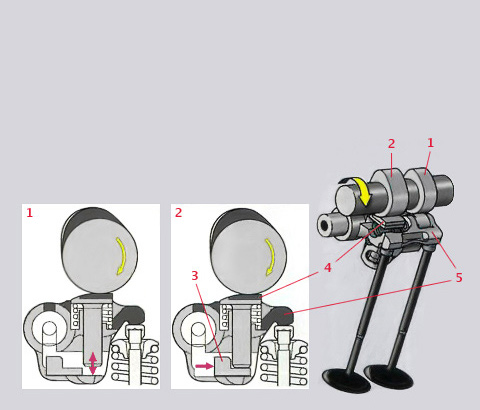
The principle of operation of the VTEC system:
A - low engine speed mode; B - transition from one mode to another; B - high engine speed mode.
1 - blocking mechanism (locking pin); 2 - small cams (low speed cams); 3 - inlet valve; 4 - rocker arm (rocker) of the first intake valve; 5 - intermediate rocker; 6 - rocker arm of the second intake valve; 7 - large cam (high speed cam).
On its camshaft there are one large and two small cams, which are connected to the two intake valves via rocker arms (rockers), and the large cam moves the free rocker arm.
With the help of a blocking mechanism with a hydraulic drive, the control system provides mode switching. The intake valves at low engine speeds operate from small cams. In this mode, the valve timing is short. When the speed increases, the blocking mechanism is triggered. A locking pin connects the rocker arms of the large and small cams together, and force is transmitted to the intake valves from the large cam.
In another modification of the VTEC system, three control modes operate. At low engine speeds, one small cam works, at medium speeds - two (opening 2 intake valves), at high speeds, a large cam works.
Modern systems are capable of turning the intake and exhaust camshafts at different angles. For Honda it is I-VTEC, for Toyota it is VVTL-i (the prefix "i" from the word intelligent - "smart"). This option significantly expands the motor control parameters.
Valvetronic system
Structurally, the most advanced type of variable valve timing systems is considered to be a system in which the valve lift is regulated. It allows you to refuse from almost all engine operating modes.
The pioneer in this direction was BMW with its Valvetronic system.
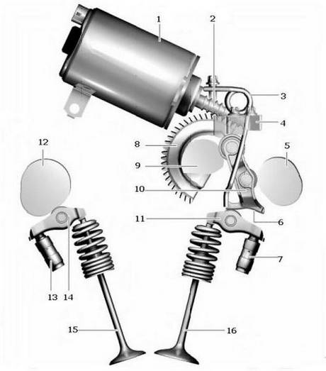
Valvetronic system:
1 - servo drive (electric motor); 2 - worm shaft; 3 - returnable spring; 4 - rocker block; 5 - intake camshaft; 6 - inclined part of the intermediate lever; 7 - inlet valve hydraulic compensator; 8 - worm wheel; 9 - eccentric shaft; 10 - intermediate lever; 11 - rocker arm of the intake valve; 12 - an exhaust camshaft; 13 - hydraulic compensator of the exhaust valve; 14 - rocker arm of the exhaust valve; 15 - exhaust valve; 16 - inlet valve.
In it, the valve lift height is changed due to a scheme in which an eccentric shaft and an intermediate lever are added to the link (cam - rocker arm - valve). It is installed only on the intake valves.
In a conventional engine, the valve timing is determined by the shape of the camshaft cam and remains unchanged in all ranges of engine operation. However, constant valve timing does not allow creating optimal mixture formation processes.
To vary the valve timing, it is necessary to change the position of the camshaft relative to the crankshaft.
Idling. In this operating mode, the camshaft angle should be set, which corresponds to the latest start of the intake valve opening (maximum delay angle, with minimum valve overlap). This ensures that the intake of exhaust gases to the intake manifold is kept to a minimum, which improves engine stability and reduces fuel consumption.
Low load mode. Valve overlap is reduced to minimize the intake of exhaust gases into the intake manifold, which improves engine stability.
Mode of medium loads. The valve overlap is increased, which makes it possible to reduce "pumping" losses, while part of the exhaust gases enters the intake manifold, which makes it possible to reduce the operating cycle temperature and, as a result, the content of nitrogen oxides in the exhaust gases.
High load mode at low engine speed. This mode provides early closing of the intake valves, which provides an increase in torque. Little or no valve overlap makes the engine more responsive to changes in throttle position, which, for example, is very important in traffic.
High load mode at high engine speed. In order to obtain maximum power at a high crankshaft speed, it is necessary to overlap the valves near TDC with a large crankshaft angle. This is due to the fact that the power depends to the greatest extent on the maximum possible amount of the fuel-air mixture entering the cylinder in a short time, but the higher the rotational speed, the shorter the time allotted for filling the cylinder.
The main tasks of the variable valve timing system are:
- improving the quality of engine idling
- reduced fuel consumption
- optimization of torque in the area of medium and high engine speeds
- an increase in internal exhaust gas recirculation with a concomitant decrease in the temperature of the gases during combustion and a decrease in the emission of nitrogen oxides
- increase in power in the area of high speeds of the crankshaft
In the 90s, more and more engines began to be equipped with variable valve timing systems in such a way that the valve overlap angle could be changed in accordance with the engine operating conditions. In these systems, used on DOHC engines (with two camshafts), a special device was mounted in the drive gear of the intake camshaft. Such devices are called variable valve timing (VIVT).
For the first time, the change in valve timing was applied to Alfa Romeo cars in 1983. After that, such systems began to be used on cars Mercedes, Nissan, BMW, Porsche, etc. The principle of operation of the camshaft rotation drive, to change the valve timing, can be mechanical, hydraulic, electrical and pneumatic.
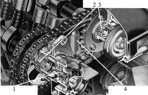
As a rule, variable valve timing is used in engines with two camshafts, one of which is used to open the intake valves, the other - the exhaust. Systems with a change in chain tension on the principle of a hydraulic ring are widely used. The change in valve timing with this type is made only for the intake valves. The camshaft for opening the exhaust valves is driven from the engine crankshaft through a gear or sprocket of a belt or chain drive 1, and the camshaft for opening the intake valves is driven by a chain drive from a sprocket installed on the camshaft of the exhaust valve drive 2.
Rice. System drive with chain tension change according to the hydraulic ring principle:
1 - camshaft drive for exhaust valves; 2 - a camshaft sprocket to drive the exhaust valves; 3 - a camshaft sprocket to drive the intake valves
The oil enters the variable valve timing system through a hole in the block head. The change in oil flows is carried out by the control valve 1, which moves the spool 2, according to the signals from the engine control unit.

Rice. A device for changing the valve timing by chain tension:
1 - control valve; 2 - spool; 3 - intake valve drive sprocket; 4.9 - chain tensioner; 5 - pusher of the chain tensioner; 6 - oil cavity; 7 - an asterisk of the exhaust valves drive; 8 - starting lock; 10 - control piston
To change the valve timing of the intake valves, a hydraulic cylinder with a piston 10 is used. When oil is supplied to the cylinder, at the signal of the control unit, the piston, extending, acts on the chain tensioner. One side of the chain begins to lengthen, and the opposite one begins to shorten, while the sprocket turns to drive the intake valves, which is not connected by the chain drive to the crankshaft. The oil supply is controlled by valve 1, controlled by an electronic control unit. The specified system has a discrete two-position variable valve timing range, since the oil pressure developed by the standard oil pump changes depending on the crankshaft speed, and can only serve to move the piston to the upper or lower position. This principle of variable valve timing has serial engines from Audi, Porsche and Volkswagen.
Depending on the signal from the control unit, the oil is directed to channels A or B. When the engine is not running, the chain tension does not change, due to the lack of oil pressure on the control piston 6. The starting lock 4 enters the groove of the control piston groove and stops it, excluding chain oscillations ... The camshaft in this case is set to a later opening of the valves, corresponding to the increase in engine power.
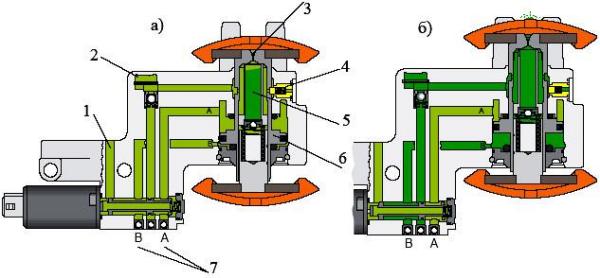
Rice. Scheme of oil supply to the variable valve timing device:
a - late valve opening; b - early opening of valves; 1 - oil return; 2 - oil supply; 3 - purge and oil hole; 4 - starting lock; 5 - oil cavity; 6 - control piston; 7 - control channels
After starting the engine, when the oil pressure begins to increase, it acts on the plane of the starting detent, overcoming the tension of its spring. The starting detent releases the control piston and, as it moves, tightens the chain, setting the valve timing to a position sooner or later, corresponding to an increase in engine torque or power. When control channel A is open, the oil acts on the piston from above and it pulls the chain downward, setting the valve opening to a position corresponding to greater power (late valve opening).
When the crankshaft speed reaches 1300 rpm, channel B opens and the oil acts on the piston from below and it pulls the chain up, setting the valve opening to a position corresponding to a greater torque (early valve opening).
The oil cavity is used to fill the pressure cavity without pressure from the plunger of the chain tensioner when starting the engine. This also has a positive effect on the noise properties when starting the engine. Hole 3 on top of the oil cavity serves for ventilation and chain lubrication.
In connection with the ever-increasing requirements for reducing emissions of toxic substances with exhaust gases, devices have now been developed that can change the valve timing over the entire range of possible engine crankshaft speed, both for intake and exhaust valves, which makes it possible to regulate the amount of residual exhaust gases in the combustion chamber. Infinitely variable valve timing also improves idle and full load performance, providing increased torque and power. A separate oil pump can be used to increase the pressure on the piston. The use of high pressure allows for a more accurate position of the camshaft depending on the engine load.
The required angle of change of the valve timing is selected depending on the load and the crankshaft speed in the field of parametric characteristics. The deviation of the required angle of rotation of the camshaft from the true angle is calculated according to the algorithm of the control unit, according to the issued value of which, the current in the oil pressure control valve changes. The control valve in turn changes the oil pressure to the actuator, which allows the camshaft to turn. The crankshaft speed is determined by inductive sensors mounted on the crankshaft or camshafts that read the speed according to gear wheels mounted on shafts.
The intake camshaft can also be rotated using a piston.

Rice. Camshaft timing device diagram:
1 - block head; 2 - a camshaft; 3 - camshaft drive sprocket; 4 - piston; 5 - electromagnet; 6 - anchor valve; 7 - helical splines; a - late phases; b - early phases; c - connection of device parts with helical splines
The device is mounted on the front end of the camshaft that controls the intake valves.
At low engine speeds, late opening of the intake valves and minimal valve overlap are ensured, which results in the lowest possible exhaust gas return to the intake duct, increasing torque and reducing fuel consumption. In this position of the armature-valve, its vertical channel is connected to the space on the right side of the piston, since the electromagnet 5 of the device is turned off. Piston 4 is pushed to the left under the influence of a spring and oil pressure flowing through the armature valve 6.
At high frequencies, at the command of the electronic engine control unit, electromagnet 5 is turned on, the core of which connects the vertical channel with the space on the left side of the piston. Oil from the central hole of the camshaft flows under the piston 4, which has internal and external oblique splines. The end of the shaft and the hub of the chain sprocket have counter splines 3. Moving in the "backward" direction, the piston, due to the splines, provides a shift of the sprocket in the circumferential direction relative to the shaft by 12 ... 15 ° towards the earlier intake. This allows the engine torque to be increased at high engine speeds. Similar mechanisms are installed on (MERCEDES-BENZ, ALFA ROMEO, etc.) with two overhead camshafts.
In the design of BMW engines, the principles of operation of both of the above-described methods of changing the valve timing are applied.
Rice. BMW infinitely variable valve timing:
1 - control piston; 2 - helical gear; 3 - spur gear; 4 - chain tensioner
The helical gear 2 can move in the longitudinal direction when the oil acts on the control piston. Moving, it shifts the camshaft drive sprocket in the circumferential direction. The use of this design allows you to change the valve timing not only for the intake (up to 60 °), but also for the exhaust valves (up to 46 °).
An alternative to the above systems is a cheaper design of the variable valve timing system, operating using a hydraulically controlled clutch.

Rice. Scheme of a continuous variable valve timing system with a hydraulically controlled clutch:
1 - oil pump; 2 - electronic engine control unit; 3 - Hall sensor for the camshaft of the exhaust valve drive; 4 - Hall sensor for the intake camshaft; 5 - a camshaft for intake valves; 6 - a camshaft for exhaust valves; 7 - electro-hydraulic camshaft distributor for intake valves; 8 - electro-hydraulic camshaft distributor for exhaust valves; 9 - working cavities; 10 - rotor; 11 - hydraulically operated clutch; a - general scheme; b - rotation of the rotor relative to the body to the right; в - rotation of the rotor relative to the body to the left

Rice. General view of the continuous variable valve timing system using a vane hydraulic motor:
The drive consists of two parts - internal with a twisting rotor 10, connected with camshaft and external 11 driven by a chain or belt drive from the crankshaft. The connection between both parts is carried out by means of an oil cavity in which the rotor projections or blades turn the rotor to the left or to the right. Simultaneously with the rotor, the camshaft turns, onto which the rotor is screwed.
The oil pressure in the working chamber depends on the engine speed, load and temperature. The position of the camshaft relative to the crankshaft during engine operation can be both variable and constant (fixed). The working cavity is powered from the engine lubrication system.
The rigid connection between the drive sprocket and the rotor connected to the camshaft only exists during engine start. Some manufacturers, for example Audi, when starting the engine, block the rotor when starting the engine with a special plunger controlled hydraulic system, which allows the camshaft of the intake valve drive to be set in the position of the most favorable intake of the air-fuel mixture. When the oil cavity is filled with oil, the inner and outer parts of the drive are separated. At the very high pressure oil, the camshafts are rotated to the position corresponding to the latest inlet of the combustible mixture and the earliest release of the exhaust gases.
The control electro-hydraulic valve 8 consists of a hydraulic part and an electromagnet. The valve is mounted on the camshaft housing and is connected to the engine lubrication system. A spool is installed in the distributor cylinder, the movement of which leads to a change in oil flows. The position of the control valve spool is controlled by a signal from the electronic control unit 2. Depending on the position of the valve, oil is supplied to the hydraulically controlled clutch through one or both channels. By connecting one or another channel, the rotor is moved to the "early" or "late" position, or it is held in a certain fixed position.
The initial position of the spool is determined by the tension of the return spring.
The camshaft adjustment range is 40 ° crankshaft angle or 20 ° camshaft angle.
DetailsWhat is the valve timing in the engine internal combustion? It is with this answer to the question that we will begin the article with you.
Gas distribution phases it is customary to consider the moment from the beginning of opening to the end of closing of the intake or exhaust valve, relative to the position of the piston (top or bottom dead center), expressed in degrees of crankshaft rotation.
In most internal combustion engines installed on cars, the valve timing is the same in all engine operating modes, that is, they remain unchanged, whether it is idle or full load at high engine speeds. As a result, all this affects the low efficiency of the engine and a decrease in its efficiency, since different operating modes require different valve timing. For example, for low revs, short phases are required with a minimum duration, for high revs, on the contrary, wide phases are required that will overlap the intake and exhaust strokes.
We know that the operation of the intake and exhaust valves is controlled by the camshaft, or rather its cams. So, in order to achieve optimal operation on engines with constant valve timing, both at low and high speeds, engineers pay special attention to the shape and size of the camshaft cams, because the timing of the valve timing depends on them.
Seeking compromises on whether to prioritize high torque at low revs or increased power at high speeds, engineers slowly came to the decision to create a system with variable valve timing... In which, for each operating mode of the engine, the valve timing will be individual.
For the first time, the variable valve timing system was applied in 1983 on the legendary Alfa Romeo car brand. After successful experience, the application of this system, it began to appear on other famous brands such as Mercedes-Benz, Porsche, BMW, Honda, etc.
The main positive qualities of this system was what it was possible to achieve:
- A noticeable improvement in engine idling.
- Reduced fuel consumption.
- Increased power.
- Optimum torque at different speeds.
- Natural recirculation of exhaust gases, and with it, a decrease in nitrogen oxide emissions into the atmosphere.
There are several ways to achieve a change in valve timing, at the moment there are three of them:
- by turning the camshaft.
- the use of cams of different shapes.
- by changing the valve lift.
This method of changing the phases has found application on the following car brands:
- Toyota - VVT-i (Dual VVT-i);
- Volkswagen - VVT;
- Honda - VTC;
- Volvo, Hyundai, Kia - CVVT;
- Renault - VCP;
- BMW VANOS;
- General Motors;
On the inlet (similarly to the outlet) camshaft there is a fluid coupling, which, under the control of the control unit, turns it at a given angle, thereby changing the valve timing.

The entire mechanism is installed on the cylinder head, from below the oil channels of the engine lubrication system are suitable for controlling both fluid couplings. Two electro-hydraulic distributors are installed on the body of the mechanism, which provide oil supply to the clutch.

consists of a rotor rigidly fixed to the camshaft and a clutch housing in the role of a timing pulley. The rotor contains oil channels through which the oil fills the chambers formed between the rotor and the housing. Filling one or another part of the chamber leads to the rotation of the rotor relative to the housing, which ultimately ensures the rotation of the camshaft at the required angle at the moment.
The system itself is designed in such a way that the control unit receives the main signals of the engine parameters: engine speed, air flow and its temperature, coolant temperature, data from Hall sensors installed on the gas distribution mechanism. Based on this data, the control unit sends signals to the electro-hydraulic distributors, which in turn control the hydraulic clutch itself, under the influence of oil pressure in the vehicle's lubrication system.

The following brands have adopted this technology: First of all, Honda again acts with its known system- VTEC;
- Toyota - VVTL-i;
- Mitsubishi - MIVEC;
- Audi - Valvelift System;
We will analyze this type of variable valve timing system using the VTEC system as an example.

The system is structured as follows: For each cylinder there are two intake valves 1, three rocker arms 2 and three cams on the camshaft. The two extreme ones are the same size 3, and the third one is in the middle of the larger 5.
- At low revs, under the influence of small cams, the force on the intake valves is transmitted through the extreme rocker arms, ensuring their opening in this mode. The middle rocker arm does not participate in this engine operating mode, which ultimately provides short valve timing.
- When the engine switches to high speed mode, the hydraulic blocking mechanism 4 is automatically triggered, which connects all the rocker arms together.
- Now only the middle cam acts on the rocker arms bigger size, which leads to lengthening of the valve timing.
In another modification of the VTEC system, unlike the previous one, there are three adjustment modes, at low, medium and high revs. This system has three cams different sizes... At low speeds, one small cam is involved, opening only one intake valve. At medium speed, two small cams open both valves. At high revs, as in the previous case, one large one opens both valves.
On modern engines Honda uses the result of two combined systems, VTEC and VTC, called I-VTEC. It is more complex than its predecessors, but at the same time, thanks to the combination of these two systems into a single whole, I-VTEC was able to expand the control parameters.
BMW made its first success with the intake valve lift system when it presented its BMW 316ti Compact with Valvetronic at the 2001 Geneva Motor Show.
After BMW's success in mastering this system, the following brands have achieved a similar result:
- Nissan - VEL;
- Toyota - Valvematic;
- Fiat - MultiAir;
- Peugeot - VTI;
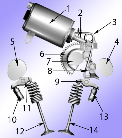
1) Electric motor (servo drive). 2) Worm shaft. 3) The spring is returnable. 4) Intake camshaft. 5) Exhaust camshaft. 6) Worm gear. 7) Eccentric shaft. 8) Intermediate lever. 9) Rocker arm inlet valve. 10) Exhaust valve hydraulic compensator. 11) Exhaust rocker arm. 12) Exhaust valve. 13) Hydraulic inlet valve lifter. 14) Inlet valve.
In the system for changing the valve lift, in addition to the classic bundle of camshaft - rocker arm - valve, there is also an eccentric shaft and an intermediate lever.
As in previous systems, everything is controlled by the control unit, which receives signals from sensors installed on the engines. Comparing all the received signals, it sends a control signal to the servo drive 1, which, through the worm shaft 2, rotates the eccentric shaft 9.
The eccentric shaft 9, in turn, changes the position of the intermediate lever 10, and it, through the rocker arm 11, the lift height of the intake valve 16 by adjusting the valve timing. Thus, this system can very accurately select the required valve timing at any speed.
› Why change the valve timing
The quality of the engine operation - its efficiency, power, torque and economy depend on many factors, including the valve timing, that is, on the timing of opening and closing the intake and exhaust valves.
In a conventional four-stroke combustion engine, the valves are driven by camshaft cams. The profile of these cams determines the moment and duration of opening (that is, the width of the phases), as well as the amount of valve travel.

Gas distribution phases in piston engines internal combustion - these are the moments of opening and closing of intake and exhaust valves (windows). The valve timing is usually expressed in degrees of crankshaft rotation and is noted in relation to the start or end moments of the corresponding strokes.
So, for example, for idling, narrow valve timing with late opening and early closing of valves without phase overlap is appropriate (the time when the intake and exhaust valves are open simultaneously). Why? Because this way it is possible to exclude casting exhaust gases into the intake manifold and the discharge of part of the combustible mixture into the exhaust pipe.

Tuners are often wise with phase shift with the help of such prefabricated sprockets. Replacing the standard camshaft with a "sports" one with other phases, you can achieve a significant increase in power.
When operating at maximum power, the situation changes dramatically. With an increase in revolutions, the opening time of the valves naturally decreases, but to ensure high torque and power through the cylinders, it is necessary to drive a much larger volume of gases than at idle. How to solve such a difficult task? Open the valves a little earlier and increase the duration of their opening, in other words, make the phases as wide as possible. At the same time, for better cylinder blowing, the overlap phase is usually made the wider, the higher the revolutions.
Honda's VTEC (Variable Valve Timing and Electronic Control), like Toyota's VVT-I (Variable Valve Timing with intelligence), allows you to smoothly change the valve timing with a hydraulically controlled phase shifter. This is achieved by turning the intake camshaft relative to the exhaust valve shaft in the range of 40-60 ° (in the angle of rotation of the crankshaft).
So when developing and fine-tuning engines, designers have to reconcile a number of mutually exclusive requirements and make difficult compromises. Judge for yourself. With the same fixed phases, the engine should have good thrust at low and medium rpm, acceptable power at high rpm. And plus to everything stably idle, be as economical and environmentally friendly as possible. That's a problem!
But the designers of such tasks have long been clicking like seeds and are capable of changing the characteristics of the engine beyond recognition by shifting and changing the valve timing. Raise the moment? Please. Increase power? No problem. Reduce consumption? Not a problem. True, sometimes it turns out that with the improvement of some indicators, you have to sacrifice others.

Doppel-VANOS (Doppel Variable Nockenwellen Steuerung) from BMW is able to move phases smoothly from the start to the end value. With the help of hydraulics, the system manages both the intake and exhaust processes.
But what if you teach the gas distribution mechanism to adapt to different engine operating modes? Easy. Fortunately, a lot of ways have been invented for this. One of them is the use of a phase shifter - a special clutch that, under the action of control electronics and hydraulics, is capable of turning the camshaft by a certain angle relative to its original position. Most often, such a system is installed at the inlet. With an increase in speed, the clutch turns the shaft in the direction of rotation, which leads to an earlier opening of the intake valves and, as a result, better filling of the cylinders at high speeds.
The gas distribution mechanism of the 3.2-liter FSI "six" from Audi is driven by chains on the flywheel side. Each camshaft has its own phase shifter.
But irrepressible engineers did not stop there and developed a number of systems capable of not only moving phases, but also expanding or narrowing them. Depending on the design, this can be achieved in several ways. For example, in the Toyota VVTL-i system, after reaching certain revolutions (6000 rpm), instead of the usual cam, an additional one begins to work - with a changed profile. The profile of this cam sets a different law of valve movement, wider phases and, by the way, provides a larger stroke. When the crankshaft is spinning up to maximum speed (about 8500 rpm) at a speed of 6000-6500 rpm, the engine seems to have a second wind, which can give the car a sharp and powerful pickup when accelerating.
The Valvetronic system made it possible to abandon the throttle valve, the system also changes the degree of opening of the valves and phases. It is applied on BMW motors since 2001. The valve stroke is changed by means of an electric motor and a complex kinematic scheme and within the range of 0.2–12 mm.
Changing the timing and duration of the opening is great. But what if you try to change the height of the rise? After all, this approach allows you to get rid of the throttle valve and shift the process of controlling the engine operating modes to the gas distribution mechanism (timing).
A similar system from the German company Mahle.
Why is the damper harmful? It degrades the filling of the cylinders at low and medium speeds. Indeed, a strong vacuum is created in the intake tract under a covered throttle when the engine is running. What does it lead to? To a large inertness of a rarefied gas environment (air-fuel mixture), a deterioration in the quality of filling the cylinder with a fresh charge, a decrease in recoil and a decrease in the response speed to pressing the gas pedal.

Nissan's Variable Valve Event and Lift System (VEL) is reminiscent of the Bavarian Valvetronic. A special eccentric, which is driven by an electric motor, shifts the fulcrum of the rocker arm, and thereby changes the valve stroke. The lift height varies between 0.5–2 mm.
That's why ideal option it would be to open the inlet valve only for the time necessary to achieve the desired filling of the cylinder with a combustible mixture. The engineers' answer is a mechanical intake valve lift control system. In such systems, the lift height and, accordingly, the duration of the intake phase change depending on the depression of the gas pedal. According to various sources, the savings from the use of a throttleless control system can be from 8% to 15%, an increase in power and torque in the range of 5-15%. But this is not the last frontier either.
This is how the “three-stage” i-VTEC (Intelligent Variable Valve Timing and Lift Electronic Control) works. At low engine speeds, fuel is saved due to the fact that half of the intake valves are practically deactivated. When switching to medium speed, the previously "dormant" valves are put into operation, but their amplitude is not maximum. In power modes, the intake valves start to operate from a single center cam. It provides maximum valve lift, in addition, its profile is specially sharpened for power conditions. The modes are controlled by hydraulics and electronics.
Despite the fact that the number and size of valves have approached the maximum possible, the efficiency of filling and cleaning cylinders can be made even higher. By what means? Due to the speed of opening the valves. True, the mechanical drive is losing ground here to the electromagnetic one.

In the fall of 2007, Toyota will launch engines with a Valvematic valve timing mechanism, which will change not only the valve timing, but also the lift of the intake valves. It is no secret that many manufacturers have been using such systems for a long time. But Toyota is launching such a system for the first time. The power of the 2-liter aspirated 1AZ-FE, thanks to the new gas distribution mechanism, was raised from 152 to 158 forces, and the moment - from 194 to 196 Nm.
What else is the plus of an electromagnetic drive? The fact that the law (acceleration at each moment of time) of the valve lift can be brought to the ideal, and the duration of the valves opening is allowed to vary within very wide limits. Electronics, according to the prescribed program, from time to time, unnecessary valves may not open, and the cylinders may be turned off altogether. What for? In order to save money, for example, at idle speed, when driving in a steady state or when braking by the engine. Yes, what modes - right during operation, the electromagnetic timing is able to turn a regular four-stroke engine into a six-stroke one. I wonder if such systems will appear on the conveyor soon?
And this is the scheme of the VVTL-i mechanism proposed by Toyota. The lift height and the opening time of both intake valves change abruptly here. When the engine is running at crankshaft speeds of up to 6000 rpm, the lift height and the duration of the opening of both valves are set by the cam (1), which acts on both valves through the rocker (5). At speeds above 6000, the law of movement of the valves is set by a higher cam (2). To put it into operation, you need to move the cracker (3) to the right (the cracker moves under the oil pressure, which rises in the control line at the right time). After the cracker has moved to the right, the cam (2) through the stem (4), which until this time freely swinging, begins to act on the valves through the rocker.
The prototype four-cylinder direct injection solenoid engine was developed by BMW. Here, the amount of air entering the cylinder is controlled by the duration of the valve opening, while the stroke is not regulated. The spring-loaded valve armature is placed between two powerful electromagnets, which are designed to hold it only in extreme positions. To prevent shock loads, the valve is braked each time it approaches the end position. The position and speed of the valve movement are recorded by a special sensor.
Perhaps a further increase in the efficiency of the motor due to the timing is already impossible. It will be possible to squeeze out even more power and torque from the same volume at a lower consumption only with the use of other means. For example, combined supercharging or structures that change the compression ratio, other types of fuel. But this is a completely different conversation.