Production time: One day
Materials at hand: ████████░░ 80%
In this article, I will show you how to make a DIY steam engine. The engine will be small, single piston with a spool. The power will be enough to rotate the rotor of a small generator and use this engine as an autonomous source of electricity on camping trips.
- Telescopic antenna (can be removed from an old TV or radio), the diameter of the thickest tube must be at least 8 mm
- Small tube for piston pair (plumbing store).
- Copper wire with a diameter of about 1.5 mm (can be found in the transformer coil or radio store).
- Bolts, nuts, screws
- Lead (at the fishing store or found in the old car battery). It is needed to mold the flywheel. I found a ready-made flywheel, but this item may come in handy for you.
- Wooden bars.
- Bicycle wheel spokes
- Stand (in my case, made of a 5 mm thick PCB sheet, but plywood is also suitable).
- Wooden blocks (pieces of boards)
- Olive jar
- A tube
- Superglue, cold weld, epoxy (construction market).
- Emery
- Drill
- Soldering iron
- Hacksaw
Steam boiler
A jar of olives with a sealed lid will serve as a steam boiler. I also soldered the nut so that water can be poured through it and tightly tightened with a bolt. I also soldered the tube to the lid.
Here is a photo:
Photo of the complete engine
We assemble the engine on a wooden platform, placing each element on a support


Steam engine video
Version 2.0
Cosmetic revision of the engine. The tank now has its own wooden platform and saucer for dry fuel tablets. All details are painted in beautiful colors. By the way, as a heat source, it is best to use a homemade
How to make a steam engine
Engine diagram

Cylinder and spool tube.
Cut off 3 pieces from the antenna:
? The first piece is 38 mm long and 8 mm in diameter (the cylinder itself).
? The second piece is 30 mm long and 4 mm in diameter.
? The third is 6 mm long and 4 mm in diameter.
Take tube # 2 and make a 4mm hole in the middle of it. Take tube number 3 and glue it perpendicular to tube number 2, after the superglue has dried, we will coat everything with cold welding (for example POXIPOL).
We attach a round iron washer with a hole in the middle to piece No. 3 (diameter is slightly larger than tube No. 1), after drying, we strengthen it with cold welding.
Additionally, we cover all seams with epoxy for better tightness.
How to make a piston with a connecting rod
Take the bolt (1) 7 mm in diameter and clamp it in a vice. We begin to wind copper wire (2) on it for about 6 turns. We coat each turn with superglue. We cut off the excess ends of the bolt.
We cover the wire with epoxy. After drying, we adjust the piston with sandpaper under the cylinder so that it moves freely there, without letting in air.
From a sheet of aluminum we make a strip 4 mm long and 19 mm long. Give it the shape of the letter P (3).
We drill holes (4) 2 mm in diameter at both ends so that a piece of knitting needle can be inserted. The sides of the U-shaped part should be 7x5x7 mm. We glue it to the piston with a side that is 5 mm.
The connecting rod (5) is made from a bicycle spoke. To both ends of the knitting needles we glue on two small pieces of tubes (6) from the antenna with a diameter and length of 3 mm. The distance between the centers of the connecting rod is 50 mm. Next, we insert the connecting rod with one end into the U-shaped part and hingely fix it with a knitting needle.
We glue the knitting needle from both ends so that it does not fall out.

Triangle connecting rod
The triangle connecting rod is made in a similar way, only on one side there will be a piece of the spoke, and on the other there will be a tube. The length of the connecting rod is 75 mm.

Triangle and spool
Cut out a triangle from a sheet of metal and drill 3 holes in it.
Spool. The spool piston is 3.5 mm long and should move freely in the spool tube. The length of the stem depends on the dimensions of your flywheel.

The piston rod crank should be 8 mm and the spool crank 4 mm.
I only live on coal and water and still have enough energy to go 100 mph! This is exactly what a steam locomotive can do. Although these giant mechanical dinosaurs are now extinct on most of the world's railways, steam technology lives on in the hearts of people, and locomotives like this still serve as tourist attractions on many historic railways.
The first modern steam engines were invented in England in the early 18th century and marked the beginning of the Industrial Revolution.
Today we are returning to steam energy again. Due to its design, a steam engine produces less pollution than an engine during combustion. internal combustion... In this video post, see how it works.
What was the power of the old steam engine?
It takes energy to do absolutely anything you can think of: go skateboarding, fly an airplane, go shopping or drive down the street. Most of the energy we use for transportation today comes from oil, but this was not always the case. Until the early 20th century, coal was the world's favorite fuel, and it powered everything from trains and ships to the ill-fated steam planes invented by the American scientist Samuel P. Langley, an early rival of the Wright brothers. What's so special about coal? There is a lot of it inside the Earth, so it was relatively inexpensive and widely available.
Coal is an organic chemical, which means that it is based on the element carbon. Coal is formed over millions of years when the remains of dead plants are buried under rocks, compressed under pressure and boiled under the influence of the Earth's internal heat. This is why it is called fossil fuels. Lumps of coal are really lumps of energy. The carbon inside them is bonded to hydrogen and oxygen atoms in compounds called chemical bonds. When we burn coal on fire, bonds break down and energy is released in the form of heat.
Coal contains about half the energy per kilogram of cleaner fossil fuels like gasoline, diesel and kerosene - and this is one of the reasons steam engines have to burn so much.
Are the steam engines ready for an epic comeback?

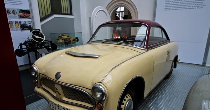
Once upon a time, the steam engine reigned supreme - first in trains and heavy tractors, as you know, but ultimately in cars as well. It's hard to understand today, but at the turn of the 20th century, more than half of the cars in the United States were powered by steam. The steam engine was so refined that in 1906 a steam engine called the Stanley Rocket even held a record for the speed on earth - a heady speed of 127 miles per hour!
Now, you might think that the steam engine was a success only because internal combustion engines (ICEs) did not exist yet, but in fact steam engines and ICE cars were developed at the same time. Since the engineers already had 100 years of experience with steam engines, the steam engine had a pretty big start. While manual crankshafts were wringing the hands of hapless operators, by 1900 steam engines were already fully automated - and without a clutch or gearbox (steam provides constant pressure, as opposed to the stroke of an internal combustion engine), very easy to operate. The only caveat is that you had to wait a few minutes for the boiler to heat up.
 However, in a few short years, Henry Ford will come and change everything. Although the steam engine was technically superior to the internal combustion engine, it could not match the price of production Fords. Steam car manufacturers tried to shift gears and market their cars as premium, luxury products, but by 1918 the Ford Model T was six times cheaper than the Steanley Steamer (the most popular steam engine at the time). With the advent of the electric starter motor in 1912 and the constant increase in the efficiency of the internal combustion engine, very little time passed until the steam engine disappeared from our roads.
Under pressure
For the past 90 years, steam engines have remained on the brink of extinction, and giant beasts have rolled out for shows. vintage cars but not much. Quietly, however, in the background, research has been quietly moving forward - in part because of our dependence on steam turbines to generate electricity, and also because some people believe that steam engines can actually outperform internal combustion engines.
ICEs have inherent disadvantages: they require fossil fuels, they generate a lot of pollution, and they are noisy. Steam engines, on the other hand, are very quiet, very clean, and can use almost any fuel. Steam engines, thanks to constant pressure, do not require engagement - you get maximum torque and acceleration instantly, at rest. For city driving, where stopping and starting consumes huge amounts of fossil fuels, the continuous power of steam engines can be very interesting.
Technologies have passed long way and since the 1920s - first of all, we are now material masters... Original steam engines huge, heavy boilers were required to withstand the heat and pressure, and as a result even small steam engines weighed a couple of tons. With modern materials, steam engines can be as light as their cousins. Throw in a modern condenser and some sort of evaporator boiler and you can build a steam engine with decent efficiency and warm-up times in seconds, not minutes.

In recent years, these advances have combined into some exciting developments. In 2009, the British team set a new steam-powered wind speed record of 148 mph, finally breaking the Stanley rocket record that had stood for over 100 years. In the 1990s, Volkswagen's R&D division, Enginion, said it had built a steam engine that was comparable in efficiency to an internal combustion engine, but with lower emissions. In recent years, Cyclone Technologies claims that it has developed a steam engine that is twice as efficient as an internal combustion engine. To date, however, no engine has found its way into a commercial vehicle.
Moving forward, it's unlikely that steam engines will ever get off an internal combustion engine, if only because of Big Oil's immense momentum. However, one day when we finally decide to take a serious look at the future of personal transportation, perhaps the quiet, green, gliding grace of steam energy will get a second chance.
Steam engines of our time
Technology.
Innovative energy. NanoFlowcell® is currently the most innovative and most powerful energy storage system for mobile and stationary applications. Unlike conventional batteries, the nanoFlowcell® is powered by liquid electrolytes (bi-ION) that can be stored away from the cell itself. The exhaust of a car with this technology is water vapor.
Like a conventional flow cell, positively and negatively charged electrolytic fluids are stored separately in two tanks and, like a conventional flow cell or fuel cell, are pumped through a converter (real nanoFlowcell) in separate circuits.
Here, the two electrolyte circuits are separated only by a permeable membrane. Ion exchange occurs as soon as solutions of positive and negative electrolytes pass with each other on both sides of the converter membrane. This converts the chemical energy bound to bi-ion into electricity, which is then directly available to consumers of electricity.

Like hydrogen vehicles, the "exhaust" produced by nanoFlowcell EVs is water vapor. But are the water vapor emissions from future electric vehicles environmentally friendly?
Critics of e-mobility are increasingly questioning the environmental compatibility and sustainability of alternative energy sources. For many, car electric drives are a mediocre compromise between zero-emission driving and environmentally damaging technologies. Conventional lithium-ion or metal hydride batteries are neither sustainable nor environmentally compatible — not in production, in use, or in recycling, even if advertising suggests pure “e-mobility”.
nanoFlowcell Holdings is also frequently asked about the sustainability and environmental compatibility of nanoFlowcell technology and bi-ionic electrolytes. Both the nanoFlowcell itself and the bi-ION electrolyte solutions required to power it are produced in an environmentally friendly way from environmentally friendly raw materials. During operation, nanoFlowcell technology is completely non-toxic and does not harm health in any way. Bi-ION, which consists of a slightly saline aqueous solution (organic and mineral salts dissolved in water) and actual energy carriers (electrolytes), is also safe for the environment when used and recycled.

How does the nanoFlowcell drive work in an electric vehicle? Similar to a gasoline car, electrolyte solution is consumed in a nanoflowcell electric vehicle. Inside the nano tap (actual flow cell), one positively and one negatively charged electrolyte solution is pumped through the cell membrane. The reaction - ion exchange - takes place between positively and negatively charged electrolyte solutions. Thus, the chemical energy contained in bi-ions is released as electricity, which is then used to drive electric motors. This happens as long as electrolytes are pumped through the membrane and react. In the case of the QUANTiNO nanoflowcell drive, one electrolyte tank is sufficient for over 1000 kilometers. After emptying, the tank must be replenished.
What “waste” is generated by a nanoflowcell electric vehicle? In a conventional vehicle with an internal combustion engine burning fossil fuels (gasoline or diesel fuel) Hazardous exhaust gases are generated - mainly carbon dioxide, nitrogen oxides and sulfur dioxide - the accumulation of which has been identified by many researchers as the cause of climate change. change. However, the only emissions from a nanoFlowcell vehicle while driving are - almost like a hydrogen vehicle - made up almost entirely of water.
After the ion exchange took place in the nanocell, the chemical composition of the bi-ION electrolyte solution remained practically unchanged. It is no longer reactive and thus is considered "spent" as it cannot be recharged. Therefore, for mobile applications of nanoFlowcell technology, such as electric vehicles, the decision was made to microscopically evaporate and release dissolved electrolyte while the vehicle is in motion. Above 80 km / h, the electrolytic waste container is emptied through extremely fine spray nozzles using a generator driven by drive energy. Electrolytes and salts are mechanically filtered beforehand. The release of currently purified water in the form of cold water vapor (micro-fine mist) is fully compatible with the environment. The filter changes by about 10 g.
The advantage of this technical solution is that the tank of the vehicle is emptied during normal driving and can be easily and quickly refilled without the need for pumping out.
An alternative solution, which is somewhat more complex, is to collect the spent electrolyte solution in a separate tank and send it for recycling. This solution is designed for such stationary nanoFlowcell applications.

However, many critics now suggest that the type of water vapor, which is released during the conversion of hydrogen in fuel cells or as a result of the evaporation of electrolytic liquid in the case of nano-removal, is theoretically a greenhouse gas that could have an impact on climate change. How do these rumors arise?
We look at water vapor emissions in terms of their environmental significance and ask how much more water vapor can be expected from widespread use. Vehicle with nanoflowcell versus traditional drive technologies and whether these H 2 O emissions could have a negative impact on the environment.
The most important natural greenhouse gases - along with CH 4, O 3 and N 2 O - are water vapor and CO 2. Carbon dioxide and water vapor are incredibly important in maintaining the global climate. The solar radiation that reaches the earth is absorbed and heats the earth, which in turn radiates heat into the atmosphere. However, most of this radiated heat is escaped back into space from the earth's atmosphere. Carbon dioxide and water vapor have the properties of greenhouse gases, forming a "protective layer" that prevents all radiated heat from escaping back into space. In a natural context, this greenhouse effect is critical to our survival on Earth - without carbon dioxide and water vapor, the Earth's atmosphere would be hostile to life.
The greenhouse effect only becomes problematic when unpredictable human intervention disrupts the natural cycle. When, in addition to natural greenhouse gases, humans cause higher concentrations of greenhouse gases in the atmosphere by burning fossil fuels, it increases the heating of the earth's atmosphere.

Being part of the biosphere, people inevitably affect the environment and, therefore, the climate system, by their very existence. The constant growth of the Earth's population after the Stone Age and the creation of settlements several thousand years ago, associated with the transition from nomadic life to agriculture and livestock raising, has already influenced the climate. Nearly half of the world's original forests and forests have been cleared for agricultural purposes. Forests are - along with the oceans - a major producer of water vapor.
Water vapor is the main absorber of thermal radiation in the atmosphere. Water vapor averages 0.3% by mass of the atmosphere, carbon dioxide - only 0.038%, which means that water vapor accounts for 80% of the mass of greenhouse gases in the atmosphere (about 90% by volume) and, taking into account from 36 to 66% Is the most important greenhouse gas for our existence on earth.
Table 3: Atmospheric share of the most important greenhouse gases, as well as absolute and relative share of temperature rise (Zittel)
Interest in water vapor as an accessible source of energy appeared along with the first scientific knowledge of the ancients. People have been trying to tame this energy for three millennia. What are the main stages of this path? Whose reflections and projects have taught humanity to derive the maximum benefit from it?
Prerequisites for the appearance of steam engines
The need for mechanisms that can facilitate labor-intensive processes has always existed. Until about the middle of the 18th century, windmills and water wheels were used for this purpose. The possibility of using wind energy directly depends on the vagaries of the weather. And to use water wheels, factories had to be built along river banks, which is not always convenient and expedient. And the effectiveness of both was extremely low. Essentially needed new engine, easily manageable and devoid of these shortcomings.
The history of the invention and improvement of steam engines
The creation of a steam engine is the result of long deliberation, success and failure of the hopes of many scientists.
The beginning of the way
The first, one-off projects were just interesting curiosities. For example, Archimedes designed a steam cannon, Heron of Alexandria used the energy of steam to open the doors of ancient temples. And the researchers find notes on the practical use of steam energy for activating other mechanisms in the works Leonardo da Vinci.
Let's consider the most significant projects on this topic.
In the 16th century, the Arab engineer Tagi al-Din developed a project for a primitive steam turbine. However, it did not receive practical application due to the strong scattering of the steam jet supplied to the turbine wheel blades.
Fast forward to medieval France. Physicist and talented inventor Denis Papin, after many unsuccessful projects, stops at the following design: a vertical cylinder was filled with water, over which a piston was installed.
The cylinder was heated, the water boiled and evaporated. The expanding steam lifted the piston. It was fixed at the upper lifting point and the cylinder was expected to cool down and the steam condensed. After condensation of steam in the cylinder, a vacuum was formed. The piston, released from the fastening, was rushed into vacuum under the influence of atmospheric pressure. It was this piston fall that was supposed to be used as a working stroke.
So, the useful stroke of the piston was caused by the formation of a vacuum due to condensation of steam and external (atmospheric) pressure.
Because the Papen steam engine like most subsequent projects were named steam-atmospheric machines.
This design had a very significant drawback - the repeatability of the cycle was not provided. Denis comes up with the idea of getting steam not in a cylinder, but separately in a steam boiler.
Denis Papin went down in the history of the creation of steam engines as the inventor of a very important detail - the steam boiler.

And since steam began to be received outside the cylinder, the engine itself passed into the category of external combustion engines. But due to the lack of a distribution mechanism that provides smooth operation, these projects have found almost no practical application.
A new milestone in the development of steam engines
For about 50 years, it has been used for pumping water in coal mines steam pump by Thomas Newcomen. It largely repeated the previous designs, but contained very important innovations - a pipe for removing condensed steam and a safety valve for releasing excess steam.
Its significant disadvantage was that the cylinder had to be heated before injecting steam, then cooled before condensing. But the demand for such engines was so high that, despite their obvious inefficiency, the last copies of these machines served until 1930.
In 1765 English mechanic James Watt, taking up the improvement of the Newcomen machine, separated the condenser from the steam cylinder.

Now it is possible to keep the cylinder constantly heated. The efficiency of the machine immediately increased. In subsequent years, Watt significantly improved his model, equipping it with a device for supplying steam from one side or the other.

It became possible to use this machine not only as a pump, but also for driving various machine tools. Watt received a patent for his invention - a continuous steam engine. Mass production of these machines begins.

By the early 19th century, more than 320 Watt steam engines were in operation in England. Other European countries also began to buy them. This contributed to a significant increase in industrial production in many sectors of both England itself and neighboring countries.
Twenty years earlier, Watt, in Russia, an Altai mechanic Ivan Ivanovich Polzunov worked on a steam engine project.
The factory bosses asked him to build a unit that would drive the blower of the smelting furnace.

The machine he built was two-cylinder and provided continuous operation of the device connected to it.
Having successfully worked for more than a month and a half, the boiler started to leak. By this time Polzunov himself was no longer alive. They did not repair the car. And the wonderful creation of a lone Russian inventor was forgotten.

Due to the backwardness of Russia at that time the world learned about II Polzunov's invention with a great delay….
So, to drive a steam engine, it is necessary that the steam generated by the steam boiler, expanding, press on the piston or on the turbine blades. And then their movement was transmitted to other mechanical parts.
The use of steam engines in transport
Despite the fact that the efficiency of steam engines of that time did not exceed 5%, by the end of the 18th century they began to be actively used in agriculture and transport:
- a car with a steam engine appears in France;
- in the United States, a steamboat begins to run between the cities of Philadelphia and Burlington;
- a steam-powered railway locomotive was demonstrated in England;
- a Russian peasant from the Saratov province patented the crawler with a capacity of 20 liters. with.;
- Attempts were made repeatedly to build an aircraft with a steam engine, but, unfortunately, the low power of these units with the large weight of the aircraft made these attempts unsuccessful.

By the end of the 19th century, steam engines, having played their role in the technological progress of society, are giving way to electric motors.
Steam devices in the 21st century
With the advent of new energy sources in the 20th and 21st centuries, the need for the use of steam energy appears again. Steam turbines are becoming an integral part of nuclear power plants. The steam that powers them is obtained from nuclear fuel.

These turbines are also widely used in condensing thermal power plants.
In a number of countries, experiments are being carried out to obtain steam from solar energy.
Reciprocating steam engines have not been forgotten either. In the highlands as a locomotive steam locomotives are still used.

These reliable workers are both safer and cheaper. They do not need power lines, and fuel - wood and cheap coal are always at hand.
Modern technologies allow capturing up to 95% of atmospheric emissions and increasing the efficiency up to 21%, so people decided not to part with them for now and are working on a new generation of steam locomotives.
If this message is useful to you, it will be nice to see you.
Oftentimes, steam engines or Stanley Steamer cars come to mind when talking about "steam engines", but these mechanisms are not limited to transportation. Steam engines, which were first created in a primitive form about two millennia ago, have become the largest sources of electrical power over the past three centuries, and today steam turbines produce about 80 percent of the world's electricity. To better understand the nature of the physical forces on the basis of which such a mechanism works, we recommend that you make your own steam engine from ordinary materials, using one of the methods suggested here! To get started, go to Step 1.
Steps
Tin can steam engine (for children)
-
Cut a rectangular hole near the base of the 4 liter paint can. Make a 15 x 5 cm horizontal rectangular hole in the side of the can near the base.
- Make sure that this can (and the other one used) contains only latex paint, and wash thoroughly with soapy water before use.
-
Cut a 12 x 24 cm strip of metal mesh. Bend 6 cm along the length from each edge at an angle of 90 o. You will have a 12 x 12 cm square platform with two 6 cm legs. Place it in the jar with the legs facing down, aligning it with the edges of the cut hole.
Make a semicircle of the holes around the perimeter of the lid. Subsequently, you will burn coal in the can to provide heat to the steam engine. If there is a lack of oxygen, the coal will not burn well. To ensure that the jar has the necessary ventilation, drill or punch several holes in the lid that form a semicircle along the edges.
- Ideally, the diameter of the ventilation holes should be about 1 cm.
-
Make a coil from a copper tube. Take about 6 m of soft copper tubing with a diameter of 6 mm and measure at one end 30 cm.Starting at this point, make five turns with a diameter of 12 cm.Fold the remaining length of the pipe into 15 turns with a diameter of 8 cm.You should have about 20 cm ...
Pass both ends of the coil through the vents in the cover. Bend both ends of the coil so that they point up and pass both through one of the holes in the cover. If the length of the pipe is not enough, then you will need to slightly unbend one of the turns.
Place the coil and charcoal in the jar. Place the coil on the mesh platform. Fill the space around and inside the coil with charcoal. Close the cover securely.
Drill the tubing holes in the smaller can. Drill a 1 cm hole in the center of the lid of a liter can. Drill two 1 cm holes on the side of the can - one near the base of the can, and the other above it near the lid.
Insert the sealed plastic tube into the side holes of the smaller can. Use the ends of the copper tube to punch holes in the center of the two plugs. Insert a rigid plastic tube 25 cm long into one plug, and the same tube 10 cm long into the other plug. They should sit tightly in traffic jams and look out a little. Insert the plug with the longer tube into the lower hole of the smaller can and the plug with the shorter tube into the upper hole. Secure the tubes to each plug with hose clamps.
Connect the tube of the larger can to the tube of the smaller can. Place the smaller jar over the larger jar, with the tube and stopper pointing away from the vents of the larger jar. Using metal tape, secure the tubing from the bottom plug to the tubing coming out of the bottom of the copper coil. Then, in the same way, secure the tube from the top plug with the tube coming out of the top of the coil.
Insert copper tube into the junction box. Using a hammer and screwdriver, remove the center section of the round metal electrical box. Secure the cable clamp with the retaining ring. Insert 15 cm of 1.3 cm diameter copper tubing into the cable tie so that the tubing extends a few centimeters below the hole in the box. Blunt the edges of this end inward with a hammer. Insert this end of the tube into the hole in the lid of the smaller jar.
Insert the skewer into the dowel. Take a regular wooden barbecue skewer and insert it into one end of a 1.5 cm long, 0.95 cm diameter hollow wooden dowel. Insert the dowel with the skewer into the copper tube inside the metal junction box with the skewer pointing up.
- During the operation of our engine, the skewer and the dowel will act as a "piston". To better see the movement of the piston, you can attach a small paper "flag" to it.
-
Prepare the engine for operation. Remove the junction box from the smaller top jar and fill the top jar with water, letting it pour into the copper coil until the jar is 2/3 full of water. Check all connections for leaks. Secure the jar lids tightly by tapping them with a hammer. Reinstall the junction box over the smaller top jar.
-
Start the engine! Crumple up pieces of newspaper and place them in the space under the net at the bottom of the engine. When the charcoal is lit, let it burn for about 20-30 minutes. As the water heats up in the coil, steam will start to accumulate in the upper can. When the steam has reached sufficient pressure, it will push the dowel and skewer upward. After the pressure is released, the piston will move downward by gravity. If necessary, cut off a part of the skewer to reduce the weight of the piston - the lighter it is, the more often it will "pop up". Try to make a skewer of such a weight that the piston "moves" at a constant pace.
- You can speed up the burning process by increasing the flow of air into the vents with a hairdryer.
-
Observe safety. We believe it goes without saying that care must be taken when working and handling a homemade steam engine. Never run it indoors. Never run it near flammable materials such as dry leaves or overhanging tree branches. Only use the engine on a solid, non-flammable surface such as concrete. If you are working with children or teenagers, then they should not be left unattended. Children and adolescents are prohibited from approaching the engine while charcoal is burning in it. If you do not know the temperature of the engine, then assume that it is so hot that it cannot be touched.
- Make sure that steam can escape from the upper "boiler". If, for any reason, the piston gets stuck, pressure can build up inside the smaller can. In the worst case scenario, the bank can explode, which very dangerous.
- Place the steam engine in a plastic boat, dipping both ends into the water to create a steam toy. You can cut a simple boat out of a plastic soda bottle or bleach bottle to make your toy more sustainable.
Cut the bottom of the aluminum can at a distance of 6.35 cm. Using metal scissors, cut the bottom of the aluminum can evenly about a third of the height.
Fold and press the headband with pliers. To avoid sharp edges, fold the rim of the can inward. Be careful not to injure yourself while doing this.
Press down on the bottom of the can from the inside to flatten it. Most aluminum beverage cans will have a round base and a curved inward. Straighten the bottom by pushing with your finger or using a small flat-bottomed glass.
Punch two holes on opposite sides of the can, 1.3 cm from the top. For making holes, either a paper hole punch or a nail with a hammer will work. You will need holes with a diameter of just over three millimeters.
Place a small tealight candle in the center of the jar. Crumple up the foil and place it underneath and around the candle to keep it from moving. Such candles usually come in special stands, so the wax should not melt and flow into the aluminum can.
Wrap the center of the copper tubing 15-20 cm long around the pencil 2 or 3 turns to form a coil. The 3mm tube should bend easily around the pencil. You will need enough curved tubing to stretch across the top of the can, plus an additional 5cm straight on each side.
Thread the ends of the tubes through the holes in the jar. The center of the coil should be over the wick of the candle. It is desirable that the straight sections of the tube on both sides of the can be the same length.
Bend the ends of the pipes with pliers to make a right angle. Bend the straight sections of the tube so that they point in opposite directions from opposite sides of the can. Then again fold them down so they drop below the base of the can. When everything is ready, you should get the following: the serpentine part of the tube is in the center of the can above the candle and goes into two oblique, looking in opposite directions "nozzles" on both sides of the can.
Dip the jar into a bowl of water, while the ends of the tube should be submerged. Your "boat" must be firmly on the surface. If the ends of the tubing are not sufficiently submerged in water, try to weigh the jar a little, but do not drown it in any way.
Fill the tube with water. The most in a simple way will dip one end into the water and pull on the other end like a straw. You can also block one outlet from the tube with your finger, and substitute the other under the stream of water from the tap.
Light a candle. After a while, the water in the tube will heat up and boil. As it turns into steam, it will exit through the "nozzles", causing the entire jar to rotate in the bowl.
Paint can steam engine (for adults)
Steam engines were installed and propelled most steam locomotives from the early 1800s to the 1950s. I would like to note that the principle of operation of these engines has always remained unchanged, despite the change in their design and dimensions.
The animated illustration shows how the steam engine works.

To generate steam supplied to the engine, boilers operating both on wood and coal and on liquid fuel were used.
First measure

Steam from the boiler enters the steam chamber, from which it enters the upper (front) part of the cylinder through the steam valve-valve (marked in blue). The pressure created by the steam pushes the piston down towards the BDC. During the movement of the piston from TDC to BDC, the wheel makes a half turn.
Release

At the very end of the piston movement towards BDC, the steam valve is displaced, releasing the remaining steam through the outlet port located below the valve. Residual steam escapes to create the sound characteristic of steam engines.
Second measure

At the same time, displacement of the residual steam valve opens the steam inlet to the bottom (rear) part of the cylinder. The pressure created by the steam in the cylinder forces the piston to move towards TDC. At this time, the wheel makes another half turn.
Release

At the end of the piston movement to TDC, the remaining steam is released through the same outlet window.
The cycle is repeated anew.
The steam engine has a so-called. dead center at the end of each stroke as the valve transitions from expansion stroke to outlet. For this reason, each steam engine has two cylinders, which allows the engine to be started from any position.