Disease dozens - frequent problems with a stove and one of them is the wrong operation of the SAUO unit. Surely you yourself have encountered or met on the Internet about problems when it does not work Nth speed stove VAZ 2110. Consider how you can repair the heater control unit.
SAUO check
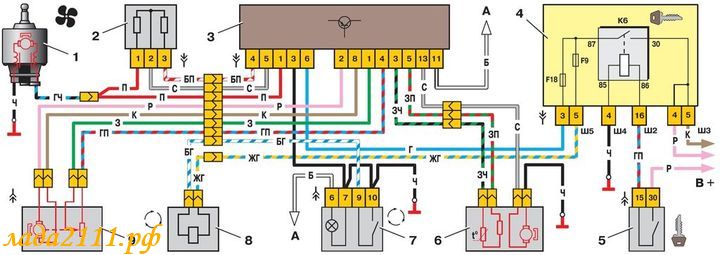
Heater automatic control system diagram: 1 - fan motor; 2 - additional resistor; 3 - controller; 4 - mounting block; 5 - ignition switch; 6 - cabin air temperature sensor; 7 - recirculation switch; 8 - recirculation valve; 9 - micromotor drive of the heater flap; A - to the instrument lighting switch; B - to power supplies
Pinout SAUO: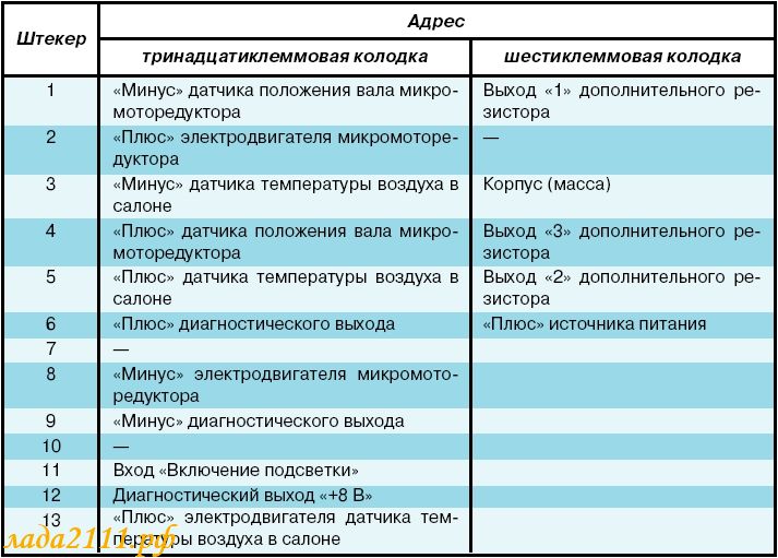
ACAD receives information from:
- - an air temperature sensor in the passenger compartment (No. 6), which has a built-in small-sized fan.
- - MMR (micromotor reducer) (No. 9), information on the position of the heater damper.
Damper control: Based on the information received and the preset air temperature, the controller controls the position of the heater flap by sending appropriate signals to the micromotor of the flap drive.
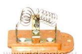
Fan speed control: to obtain a low speed (all but the last), an additional resistor (No. 2) is used, which has two spirals with a resistance (0.23 and 0.82 Ohm). When both spirals are connected to the electric motor power circuit, the 1st fan speed is provided, if the spiral with a resistance of 0.23 Ohm is turned on - the 2nd speed. When the electric motor is turned on without a resistor, the fan rotor rotates at the maximum 3rd speed (4100 min-1).
If the knob of the fan operating mode switch is in position A, the controller also controls the fan speed depending on the difference between the air temperature in the passenger compartment and the temperature sensor.
SAUO adjustment
Place a regular mercury thermometer near the ceiling temperature sensor. Turn on the heater controller and set the fan control knob to the ‘A’ position, and with the temperature setpoint 2C higher than the air temperature in the passenger compartment. If, with the doors and windows closed, after 15 minutes in the cabin, the temperature does not correspond to the set one, then the stove control unit should be adjusted.
To adjust, pull out the SAUO unit from the slot and rotate the regulator on the left side of the controller:
Check the operation of the heating system again by repeating the above steps.
Repair of SAUO
Before performing repair of the SAUO VAZ 2110 unit it is worth making sure that the problems with the stove are associated with him. To do this, you must connect a known working heater control unit (take it from a friend or in a store). If there are no problems with the stove with the SAUO working unit, then we try to find out what is the reason. If the working unit of the SAUO obviously did not help, then the problem with the stove is different.
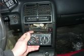
We remove the buttons next to the SAUO block. We take out the stove control unit.
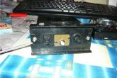
We set the regulators to position 0 and remove and then remove the front cover and glass from the latches. Unscrew 2 screws at the front and 1 at the back. 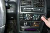
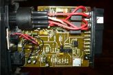
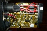
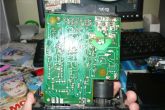
We remove the board from the plastic case and check the integrity of all tracks, jumpers and resistors.
In this example, the 1st speed of the stove did not work, because the jumper was broken. We solder it on one side and on the other. 
Reassemble in reverse order. Now all speeds of the SAUO unit work.
FAQ on the operation of the VAZ 2110 stove
The 1st speed of the stove does not work
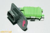
- All stove fan speeds (except for the last one) are connected through an additional heater resistor, which is located under the frill (wind pad). One of the reasons when the first speed of the heater does not work is a malfunction of this resistor. Depending on the SAUO unit, this additional resistor differs:
 used on the oldest SAUO units, which have only 2 speeds. (0 A 1 2).
 installed on a modified heater before September 2003, the SAUO unit has 3 speeds (0 A 1 2 3).
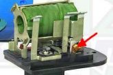
The most common malfunction in this resistance is that all stove speeds stop working, except for the maximum 3. The reason is that the thermal fuse is soldered off (indicated by the red arrow), it is treated by soldering it into place. But if it is unsoldered and later, you need to look in the direction of the motor, the motor takes a very large current (not lubricated, wear of the brush assembly, etc.).
 installed on the last heaters since September 2003, the SAUO unit has 4 speeds and does not have an auto mode (0 1 2 3 4).
- In addition to the malfunction of the additional heater resistor, the problem may also be in the contacts of the stove control unit board. Not infrequently, due to the high temperature, the board heats up a lot and the contact is unsoldered. Look carefully at all the contacts on the boards, especially in the places where the power is supplied.
- Clean up contacts.
How to replace the RDO sensor for VAZ 2110 2002 Written by Dankn.
Only speed 4 worked for me, the rest did not.
You will need a long Phillips screwdriver. 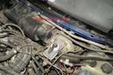
How to replace the RDO sensor in the service manual.
The second speed of the stove does not work
- The reason is exactly the same as in the case when the first speed of the heater does not work.
The third speed of the stove does not work
The 4th speed of the stove does not work
- The reason is exactly the same as in the case when the third speed of the heater does not work.
The stove at 1 and 2 speeds blows the same way, that is, there is almost no difference between the first speeds, and at 3 speeds it blows much stronger
- The reason is the additional heater resistor, it needs to be replaced.
The temperature on the stove control unit is not regulated or the stove fan does not work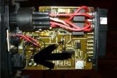 Disassemble the SAUO block and carefully review all the tracks and contacts. If there are no visible defects, then you need to look for the cause in disassemble (indicated in the photo).
On the VAZ-2110 (2002), the stove began to issue only cold, or only hot air, and the fan began to work only on maximum speed... It turned out that the heater flap position sensor was worn out (carbon variable resistor - out of order) and the additional resistor of the stove fan motor burned out. Even earlier, the fan had several high and very high speeds.
After evaluating the scope of repair work and the cost of spare parts, it was decided to make a control unit that would work with the indicated malfunctions, and surpass the factory version in terms of costs and properties.
Happened…
After 4 years of operation, the double-sided tape has dried, securing the front panel with button overlays. Hastily pasted on "Moment", corroded the paint, appearance Suffered.
Main advantages:
- There is no need to buy a new heater motor with a sensor (≈1500 p-sold only as an assembly) and change it.
- There is no need to buy a new heater fan resistor (≈300 r) and change it.
- There is no need to buy a new interior temperature sensor (which chirps near the ear from above) (≈300 r) and change it.
- Modern look and functionality. Fan speed control from zero. Maintaining the set temperature.
- Cheapness of components (300-500 r).
The structure is assembled in the body from the old block. The stock board has been removed. The front panel is peeled off. Only the plastic case remains.
Device controls:
- external temperature sensor DS18S20 in TO-92 housing (DS1820), located in the passenger compartment near the air duct.
- buttons for setting temperature and fan speed
- electronic end sensors - implemented schematically and programmatically.
Let's move on to the schematic diagram.
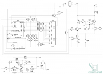
The circuit contains some unusual circuitry solutions, but - they are tested and work well. An interesting control circuit from the microcontroller by the direction of rotation of the collector motor (12 V) with the definition of jamming. Also of interest is the FET gate driver circuit.
The circuit is based on a PIC16F628A microcontroller in a DIP18 package and is powered by an internal 4 MHz oscillator. The microcontroller is installed in a "crib" for extraction during firmware.
Instead of the heater flap motor position sensor, end position sensors are introduced. Their work is based on the principle of increasing the motor current when jammed. With an increase in current, the voltage across the resistor R24 increases to 0.4-0.6 V, the VT4 transistor (BC337-40) opens, at pin 3 (RA4) of the microcontroller, the signal changes from "1" to "0". The microcontroller receives the "end position" signal.
The temperature is controlled according to the data of the external DS18S20 temperature sensor by small movements of the damper. In case of malfunction or breakage of the sensor - movement of the damper when pressing the buttons "+", "-" C o.
On transistors VT5, VT8 (BC337-40) and VT6, VT7 (BC327-40), a control circuit for the damper collector motor is assembled. With log 1 on one of the pins 1 (RA2), 2 (RA3) of the microcontroller, the motor rotates in the required direction.
The VAZ-2110 fan motor consumes up to 16 A, it is controlled by PWM, by means of a powerful field-effect transistor VT1 (IRFZ48N). Powerful diode VD4 (2D213A) is designed to suppress the effect of motor inductance. On transistors VT9 (BC337-40), VT10 (BC327-40), optocoupler V1 (PC817C) and diode VD1 (1N4007), the gate driver circuit of the field-effect transistor is assembled. Used hardware PWM microcontroller from output 9 (B3). It operates at a frequency of about 20 kHz.
LED indicator - double green (LTD585G "LITEON"). Dynamic indication is used by means of keys VT2, VT3 (BC337-40). The control buttons are connected to the same ports of the microcontroller as the indicator. The buttons are polled at a frequency of about 4-5 Hz. During this time, the indicator turns off (a few microseconds - not visible to the eye).
The analog temperature sensor (thermistor) circuit R19, C6 is not used. But if someone has a desire, then it can (and even should) be used.
Power supply of the digital part from +5 V stabilizer type KREN5A or imported analogue 7805.
Setting up the device
Setting up the device consists in the correct connection of three wires: +12 V, ground, + fan (K10) to the 6-pin "male" car block (buy at a car dealer). And in connecting two wires with 3mm "dads" to the contacts of the gear motor in the standard connector (K11, K12). If the temperature is not regulated correctly (jumping from minimum to maximum), then these two contacts must be reversed. The connection is made in accordance with the VAZ-2110 wiring diagram.
Algorithm of the microcontroller:
1. When you turn it on for the first time after flashing, calibration takes place: the time of movement from one extreme position to another is measured. (It is important that the voltage is close to the operating voltage, it is desirable to start the engine within 10 seconds).
2. "88" is displayed to check the indicators.
3. Initial temperature measurement. Determination of the serviceability of the temperature sensor. If the difference from the set value is large, then the damper is moved to the corresponding end position (if the temperature sensor is faulty, it is not performed).
4. The main cycle of work:
- Temperature measurement with a period of 5-6 s. Determination of the serviceability of the temperature sensor. If it differs from the set one, the damper is moved. (From 1 to 3 conventional steps (if not the extreme position). Step is the time when the damper motor is turned on. The time depends on the initial calibration.)
- Polling buttons and changing setting values. When the temperature changes, it writes to FLASH (memorization). When the rotation speed changes, the PWM duty cycle changes.
- After 5-6 seconds, the brightness of the indicators decreases to one quarter. Indicators show the current temperature.
- With a frequency of 40-50 Hz, there is a dynamic indication of the current parameter (rotation speed, set temperature, measured temperature (brightness-0.25)).
The original draft is attached and well commented.
The project was created in P-CAD2001 and Microcode Studio (PIC-BASIC). Microcontroller programming - using a JDM programmer (a simplified version of 3 resistors is the simplest JDM programmer).
When programming: INT RC-I / O, WDT-OFF, PWRT-ON, MCLR-ON, BODEN - ON, LVP-OFF, CPD-OFF, CP-OFF.
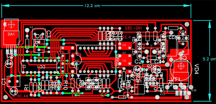
The board is single-sided with wire jumpers. Manufactured. It is located at the front of the case where the control knobs used to be. To manufacture the board, you need to download or "buy" any P-CAD from 2000 and print the template.
List of radioelements
| Designation | Type of | Denomination | Quantity | Note | Shop | My notebook |
|---|---|---|---|---|---|---|
| DD1 | MK PIC 8-bit | PIC16F628A | 1 | Search in LCSC | Into notepad | |
| DA1 | Linear regulator | LM7805 | 1 | Search in LCSC | Into notepad | |
| V1 | Optocoupler | PC817 | 1 | PC817C | Search in LCSC | Into notepad |
| VT1 | MOSFET transistor | IRFZ48N | 1 | Search in LCSC | Into notepad | |
| VT2-VT5, VT8, VT9 | Bipolar transistor | BC337-40 | 6 | Search in LCSC | Into notepad | |
| VT6, VT7, VT10 | Bipolar transistor | BC327-40 | 3 | Search in LCSC | Into notepad | |
| VD1-VD3 | Rectifier diode | 1N4007 | 3 | Search in LCSC | Into notepad | |
| VD4 | Rectifier diode | 2D213 | 1 | Search in LCSC | Into notepad | |
| temperature sensor | DS18S20 | 1 | Search in LCSC | Into notepad | ||
| R1 | Resistor | 10 kΩ | 1 | Search in LCSC | Into notepad | |
| R2, R20-R23, R25, R26 | Resistor | 5.1 k Ohm | 7 | Search in LCSC | Into notepad | |
| R3 | Resistor | 10 ohm | 1 | Search in LCSC | Into notepad | |
| R4, R6, R8, R10 | Resistor | 22 k Ohm | 4 | Search in LCSC | Into notepad | |
| R5, R7, R9, R11 | Resistor | 1 kΩ | 4 | Search in LCSC | Into notepad | |
| R12-R18 | Resistor | 240 Ohm | 7 | Search in LCSC | Into notepad | |
| R19 | Thermistor | 1 |
High-quality operation of a car stove in winter is one of the main conditions for comfortable driving. In domestic vehicles, even in new models, the heater is one of the problematic elements, which very often fails. And if in the summer you can close your eyes to this, then in the cold you immediately have to take measures to eliminate the problem.
To eliminate the malfunction, first it is important to diagnose which element heating system the car is out of order, and. The easiest way is to turn to specialists for help, but their services are not very cheaply priced. Very often, vehicle owners are engaged in troubleshooting and repairing the heater on their own, since domestic cars are highly maintainable.
This article will discuss how to diagnose a malfunction of the VAZ-2110 heater control unit and repair it yourself.
Design features of the VAZ-2110 stove control unit
One of the common problems of the heating system that the owners of the VAZ-2110 face is the failure or malfunctioning of the stove control unit. Dozens from the factory are equipped with stoves, which are coordinated through an automatic heater control system. In abbreviated form, the system is called the SAUO block. The main indicators of its malfunction is the operation of the heating system not in all modes. If one or several stove speeds do not work, then most often the problem is in the SAUO unit. Thanks to the VAZ-2110 electronic module, the temperature set by the driver is maintained in the car.
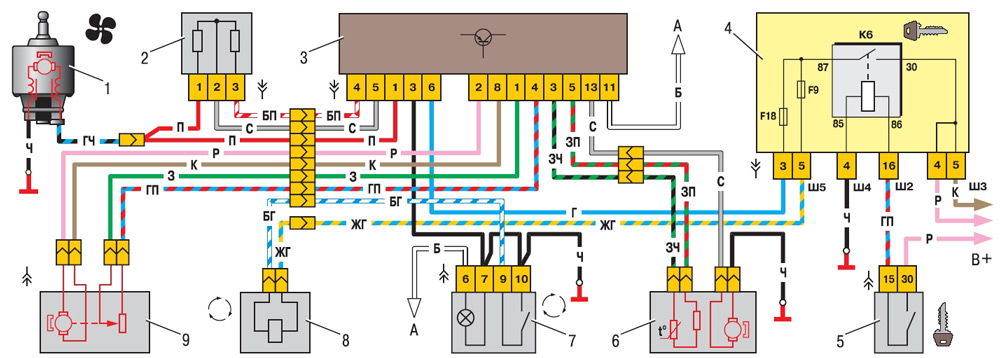
Heater automatic control system diagram: 1 - fan motor; 2 - additional resistor; 3 - controller; 4 - mounting block; 5 - ignition switch; 6 - cabin air temperature sensor; 7 - recirculation switch; 8 - recirculation valve; 9 - micromotor drive of the heater flap; A - to the instrument lighting switch; B - to power supplies
Before proceeding with the repair of the VAZ-2110 heater, you need to find out which stove is on your vehicle. Cars that were produced before September 2003 are equipped with old-style stoves. Accordingly, there are significant differences in the design, which are important to pay attention to when repairing.
The SAUO unit consists of electronic elements, the coordination of which takes place with the help of handles on the central console of the machine.
The VAZ-2110 stove control unit is equipped with a controller with two handles. The right handle is responsible for turning on a certain fan speed. An additional resistor is directly responsible for switching its speeds. Old-style stoves have resistors for two or three fan speeds. The stoves of the new model are equipped with a modified resistor RDO 2123-2118022. The coordination unit of the improved stove model has four speeds and does not have an auto mode.
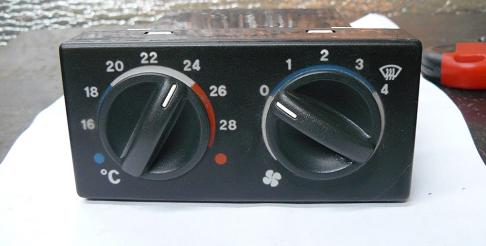
The left handle is responsible for turning on the temperature regime in the cabin vehicle... Depending on the position of the handle, information about the preset air temperature is sent to the micro-reducer of the damper drive and, with the help of the controller, the required damper position is set. With the help of the regulator, you can set the temperature regime from sixteen to thirty degrees Celsius.
Until 2003, old-style stoves with four- and five-position controllers were installed in cars, which have now been discontinued and are very difficult to find. And also a simple VAZ-2110 heater control unit is not suitable for car models that were produced after 2003 and are equipped with modified stoves from the factory.
Accordingly, before buying parts for repairing a vehicle's heating system, you need to look at which heater model is on your top ten. Stoves differ not only in the SAUO unit, but also in the heater radiator, micro-reducer, and resistors.
Diagnostics of serviceability and dismantling of the stove control unit
The SAUO module is located on the center console of the car and is responsible for the correct heating of the passenger compartment. Repairing the VAZ-2110 stove control unit requires certain knowledge in electronics, therefore, before proceeding with the repair of the part, it is necessary to determine whether the problem is really in the electronic module itself.
To do this, you must initially dismantle the unit and install a knowingly serviceable part in its place. Take the SAUO unit from friends or at a service center to diagnose your car.
Before carrying out any work on the car that concerns the electronics and wiring, disconnect the power supply to the battery to avoid shorting or burning out the electronic components.
Then you can proceed directly to the removal of the unit, through which the functionality of the stove is coordinated. For this, the buttons on the sides of the stove are initially dismantled. The heater regulators must be switched to zero positions. Only then can the module be pulled out. This must be done very carefully, as the power plugs are connected to the rear of the unit. Once you see them, you must carefully disconnect them so as not to damage the contacts. At this, the dismantling can be considered complete.
A working unit is installed on a regular seat, and the operation of the car's heating system is checked. If the stove functions correctly with the new unit, it means that there is a malfunction in the SAUO unit itself. Otherwise, it is necessary to diagnose other elements of the heating system.
DIY VAZ-2110 heater control unit repair
If it turns out during diagnostics that the problem is in the stove control module, then it must be tried to be repaired or. Since the price of new electronic units is quite high, the right decision would be to repair the control part, especially since this requires only basic knowledge of electronics, the ability to use a tester and a soldering iron if necessary.
Before starting work, you need to disassemble the heater control unit. For this, the front cover with regulators is removed from the latches from the previously dismantled electronic module. Then a special glass cover is detached. Using a screwdriver, loosen two screws on the front of the unit and one on the back. After that, the top cover of the module can be removed; this must be done very carefully so as not to damage the contacts inside the part.
Inside the module there are electronic tracks, contacts and resistors, which are responsible for the high-quality functioning of the controllers of the car's heating system. It is necessary to inspect all contacts, electronic tracks on the board, resistors and jumpers. The board can become very hot from high operating temperatures, which will lead to the disconnection of the contacts. Particular attention should be paid to the power supply points, to clean the contacts. If there is visible damage to the electronic circuit, it is necessary to solder the damaged elements. In parallel, using a tester and an ohmmeter, the functionality of the electronic elements and resistors on the board is checked. If necessary, replace the non-working parts on the board of the SAUO module.

After troubleshooting, the heater control unit is assembled in the reverse order and installed in its original place. Next, you need to connect the battery power and check the operation of the vehicle's heating system; if necessary, the heater controller is adjusted.
Adjusting the fuser controller
The manufacturing plant provides for heating the passenger compartment to the specified temperature in fifteen minutes with a deviation of up to two degrees. Use the controller knob to set a comfortable temperature regime in the car.
To check that the stove is functioning properly, use a conventional mercury room thermometer. If, after fifteen minutes, the interior has not warmed up to the required temperature, the controller must be adjusted.
To do this, pull out the stove control module back and turn the temperature regulator first to the maximum value, then in the opposite direction. After carrying out these actions, install the unit in place and check the operation of the stove again.
In parallel, it is necessary to check the operation of the heater flaps. If when switching temperature regimes there are extraneous sounds, then you need to check the condition of the dampers. If cold air does well, but the hot one hardly does - then. In the absence of a normal flow of cold air with a good supply of hot air, there is a problem with the upper damper. The reason may be the deformation of the dampers under the influence of air at different temperatures. In this case, it is better to replace the standard plastic dampers with aluminum counterparts, which are more resistant to temperature extremes.
After adjusting the controller, all heater elements are installed in their original places. Assembly is carried out upside-down.
Let's sum up
Malfunctions of the VAZ-2110 stove control unit can lead to both incorrect functioning of the car's heating system and a complete failure of the stove. In the cold season, this will affect not only a comfortable stay in the car, but also a safe driving for the vehicle driver.
The stove control unit can be repaired on their own having a basic knowledge of electronics, a desire to work and improve your comfort.
High-quality repairs and timely regular checks of the unit before the onset of cold weather will help you save money on stove repair services in service centers and the purchase of expensive elements of the heating system.
The best prices and conditions for the purchase of new cars
Credit 4.5% / Installment / Trade-in / 95% of approvals / Gifts in the salonMas Motors
Features of the device
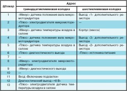
The system is designed to ensure the desired temperature in the vehicle interior. The control unit of the system is controller 3 (Fig. 7-47) of type 13.3854, which has two control handles. The left knob (temperature dial) sets the desired temperature in the passenger compartment (range from 16 to 30 C), and the right knob sets the fan operating mode: 0 - fan off, I - medium fan speed, II - low fan speed, A - automatic fan control. The controller shutdown button is located between the control handles. The addresses of the controller output plugs are given in table. 7-7.
Table 7-7
Addresses of the output plugs of the heater control system controller
The controller receives information from:
- sensor 6 for air temperature in the passenger compartment (a small-sized fan is built into the sensor);
- the position sensor of the micromotor drive shaft 9 of the heater flap drive, i.e. information about the position of the heater flap.
On the basis of the information received and the set air temperature, the controller controls the position of the heater flap by sending appropriate signals to the micromotor of the flap drive.
If the knob of the fan operating mode switch is in position A, the controller also controls the fan speed depending on the difference between the air temperature in the passenger compartment and the temperature sensor.
For accelerated heating of the air in the passenger compartment, a recirculation valve 8 with a switch 7 is used. When the valve is turned on, the flow of outside air into the passenger compartment is shut off and only interior air circulates through the heater.
Heater fan motor 1 used type 45.3730, with permanent magnet excitation.
To obtain a low speed, an additional resistor 2 is used. It has two spirals - one with a resistance of 0.23 Ohm and the other - 0.82 Ohm. When both spirals are connected to the electric motor power circuit, the 1st fan speed is provided, if the spiral with a resistance of 0.23 Ohm is turned on - the 2nd speed. When the electric motor is turned on without a resistor, the fan rotor rotates at a maximum 3rd speed (4100 min -1).
Data for checking the fan motor
Shaft rotation frequency at electric motor load by impeller * at voltage 12 V and temperature (25 ± 10) С, min -1 ..... 4100 ± 200
Consumption current at the specified load and speed, no more, A ...... 14
* Corresponds to a shaft load with a torque of 0.216 Nm (0.022 kgfm)
Heating system regulation
Place a mercury thermometer near the interior temperature sensor and measure the interior temperature. Turn on the heater controller, set the fan control knob to position A, set the temperature by the controller temperature dial 2 C higher than the air temperature in the passenger compartment and hold it for 15 minutes with the doors closed and the door windows raised.
If after 15 minutes the air temperature in the passenger compartment does not correspond to the set one, then remove the controller from the socket and use the regulator (variable resistor brought out under the slot on the left side of the controller) to adjust the temperature setting.
To increase the temperature, turn the regulator clockwise, and to decrease it, turn it in the opposite direction.
Check the operation of the heating system again by repeating the above steps.
A common disease of VAZ 2110 cars is problems with the stove.
First, you need to remove the central nozzles, move the air flow direction knob as far as possible to the left (position - everything to the passenger compartment) and see the "behavior" of the damper. Turn on the ignition, change the position of the temperature regulator from the blue point ("minimum") to the red point ("maximum") and look at the damper.
If during such a check the damper does not move, then there is a high probability that the problem is in the jammed micromotor of the heater damper drive.
Sometimes there is also a destruction of the seat of the plastic flap. This malfunction of the VAZ 2110 can be detected by ear when it is heard that the gearbox is working, and the damper does not change its position. And sometimes you can hear clicks of turning the square shaft in the seat.
Therefore, if the flap does not move during such a check, then the first step is to try to help the gearbox. To do this, turn on the ignition and, moving the temperature knob from the left extreme position to the right, pull the damper with your hand. This must be done carefully and without undue effort. If it starts working, then this is not yet a successful completion of the repair, because if the reason for the jam is found, it will still jam again sooner or later. But if it stopped wedging and the damper started working, then the reason must be looked for in the gearbox itself.
Checking SAUO for VAZ 2110.
Heater control circuit
To check the automatic heater control system, connect the tester to terminals x1.2 (pink) and x1.8 (brown). Then turn on the ignition (SAUO functions only when the ignition is on). When the temperature knob is moved to the extreme positions, a control voltage of 10 V should appear for 10-15 seconds. In addition, the polarity of the control voltage should change with any transfer of the temperature knob to the extreme positions. In the case of a complete absence of voltage, we can say that the SAUO controller is faulty.
A warning! You cannot close these contacts and apply any voltage to them (for example, "+" of the battery), since the output of the SAUO operational amplifier, which is designed for only 1 A, will break, therefore, you will need to repair or replace the unit. I must say that the blocks of the old model (there are several types and all with the letter "A", with automatic speed, the speed handle has four or five positions) are interchangeable with each other, but not interchangeable with the block of the new model (where there is no letter "A" and five speed positions - "0-1-2-3-4").
If the operation of the heater is noticed only in extreme positions, or there is a suspicion that the gearbox is working, but its shaft turns in the damper socket, then it is necessary to check the serviceability of the damper position sensor.
In the case of moving the temperature knob to the extreme positions, the resistance at the contacts x1.1 (green) and x1.4 (cyan with a purple stripe) should change. There will be different limits on the type of ACAD, as well as on the microreducer model used with it:
- for the old model 800 Ohm (hot), 3.2 KOhm (cold),
- for a new sample 5 KOhm (hot), 1.2 KOhm (cold).
If there is no resistance at all, or if the gearbox shaft rotates, but the resistance does not change, then the reason is a breakdown of the damper position sensor. It changes assembled with a micro-reducer, and can be rearranged from a reducer of a similar type.
If it is noticed that the SAUO controller is functioning and gives out a control voltage to the micromotor reducer, but the damper does not change its position, then it is necessary to repair the auto VAZ 2110, namely to remove and check the micromotor reducer directly. It is adhered to the heater body with three self-tapping screws, and it can be removed without removing the heater.
Removing the heater micromotor reducer.
First, remove the wipers, unscrew the self-tapping screws (indicated by the arrows in the photo, then unscrew the two nuts on the sides, carefully remove the plastic hook from the hole in the body, and then remove the frill.
To make it convenient in the future to carry out repairs of VAZ 2110 cars, you can slightly improve the washer fluid supply system windshield... So, cut the fluid tube and insert the plastic connector into it. In this case, a piece of tubing from a can of polyurethane foam is used.
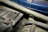
When the frill is removed, access to the micromotor reducer will open.
It is located to the left of vacuum booster brakes, therefore, in order to unscrew 3 of its fastening screws, you will have to use either a very long or very short screwdriver.
After removing the gearmotor and leaving its shaft from the damper seat, the damper itself will go to the "cold" position.
Now we start disassembling the micromotor gearbox.
To do this, use a thin screwdriver to carefully release the hooks of the housing, and split the housing of the micromotor gearbox.
Insert the wires powered by the SAUO into the motor connector and check if it is spinning at all.
If the motor does not spin, then it is recommended to replace it with a new one. However, you can try to revive it. To do this, mark the position of the motor cover in relation to its body. This must be done in order not to inadvertently reverse the polarity during assembly. Then carefully bend the side, pressed in two places, and remove the cover from the motor.
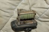
Now we turn to the disassembly of the motor.
Check the condition of the collector and motor brushes, and then check the condition of the bearing in the housing.
If the motor did not work, then you can try to find and eliminate the cause, or you can replace it with a new one. If the motor was serviceable, then lubricate the bearings with silicone grease.
Next, check the condition of the gears of the reducer. A very common cause of a gearbox breakdown (if the motor is in good working order) is shear / breakage of one or more teeth of the gearbox gear. In this case, it is also recommended to replace either the defective gears or the entire gearbox. But you can try to repair the damaged gear.