Regulate by changing: the frequency of the supply network current; the number of pole pairs of the stator winding; parameters of the stator or rotor circuit. For asynchronous electric motors, all three control methods are used, for synchronous - only the first one.
For collector motors alternating current the speed is adjusted in the manner indicated for the electric motor direct current with consistent excitement.
Speed control by changing the current frequency is the most economical, but a separate generator or converter with variable frequency and voltage is required to power the electric motor. With this method, it is necessary to strive for the characteristics of the asynchronous electric motor to have sufficient rigidity, which is provided by joint regulation of the frequency of the current and voltage.
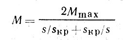
With a proportional decrease in the frequency of current and voltage, the rigidity of the mechanical characteristic 1 (Fig. 1) and the maximum torque Mmax decrease slightly compared to the natural characteristic 0. The advantages of frequency regulation include a wide range (up to 12: 1) and smoothness.
Speed control by changing the number of pole pairs is used only for asynchronous electric motors with a squirrel-cage rotor, since motors with a wound rotor would require simultaneous switching of the rotor winding, which complicates its circuit and design.
The number of pole pairs can be changed by switching the number of sections of one winding or by switching two independent windings. In the first case, the stator winding consists of two equal parts connected in series or in parallel. Such switching allows you to change the number of pole pairs by 2 times and, therefore, change the speed of the electric motor in a ratio of 2: 1. The use of two windings with a different number of pole pairs allows you to change the speed in different ratios, for example, 1: 3; 2: 3, etc.

Rice. 1. Mechanical characteristics asynchronous motor at different current frequency
Motors capable of operating at two different numbers of pole pairs are called two-speed motors. They are designed to operate with constant torque or constant power.
In addition to two-speed motors, three- and four-speed ones are used. The industry produces two-speed motors with one winding in the stator, three- and four-speed motors with two windings, which in turn can be switched in a 2: 1 ratio. This method of regulation is economical (motors have rather rigid characteristics), but requires a complex switching device; in addition, for motors with two windings, the use of active copper is sharply reduced, since when one of the windings is operating, the other is turned off. However, due to their advantages, motors with switching the number of pole pairs are widely used in marine electric drives that do not require smooth speed control (capstan, windlass, etc.).
Regulation by changing the parameters of the electric motor circuits is common in motors with a wound rotor. When an active resistance is introduced into the rotor circuit, the engine speed decreases at the same torque value (). This method is uneconomical, requires an expensive and cumbersome rheostat, and the decrease in the rotational speed is 10–20%; therefore, in ship conditions it is used relatively rarely and mainly for short periods of time.
Synchronous motors start. A distinction is made between direct starting and starting with starting current limitation.
Direct start is simple, but when turned on, large inrush currents occur, reaching values I p = (4-7) I nom.
When the electric motor is powered from a power plant of limited power, inrush currents can cause unacceptable short-term voltage drops, disrupting the operation of switched-on receivers electrical energy... Therefore, direct start is used if the power of the electric motor is many times less than the power of the power plant from which it is powered.
With an electric motor power commensurate with the power of a power plant, use different ways starting with starting current limitation: switching the stator winding of the motor with; with help ; the inclusion of resistors in the stator circuit; the inclusion of reactors in the stator circuit; the inclusion of resistors in the rotor circuit (for motors with a wound rotor).
When starting by switching the stator windings from "star" to "delta", the Q1 switch first closes, while the stator windings of the motor turn out to be switched on "star" (Fig. 2, a). After the motor has accelerated, switch Q1 is opened, and switch Q2 is closed, and the windings are delta-connected. With this method starting current decreases 3 times.

Rice. 2. Starting the engine by switching from "star" to "delta"
The advantage of the method is its simplicity, the disadvantage is that the starting torque is also reduced by a factor of 3 (Fig. 2, b). The decrease in torque is explained by the fact that when the windings are connected by a "star", the voltage across them is √3 times less than when connected by a "triangle", and as can be seen from the formula (), the torque depends on the voltage to the second degree. In some cases, the starting torque when connecting the windings with a "star" turns out to be insufficient, then the application of the method becomes impossible.
The advantage of starting the engine using an autotransformer over the previous method is the ability to set any initial voltage (Fig. 3, a) and then gradually increase it. The disadvantages of this method are the high cost, large mass and dimensions starting autotransformer. The characteristics are shown in Fig. 3, b.
The inclusion of resistors (Fig. 4, a) or reactors in the stator circuit during start-up leads to large active losses in the case of resistors and a decrease in the power factor in the case of reactors, however, due to the simplicity of these methods, they are widely used. As can be seen from the formulas () and (), the inclusion of elements in the stator circuit increases the critical rotation frequency M max1 and decreases the moment M max (characteristic 1, Fig. 4, b).
The starting of motors with a phase rotor is carried out using starting rheostats included in the rotor circuit (Fig. 5, a).
The starting rheostat consists of three to four sections of resistors for each phase. As the engine accelerates, the rheostat sections are alternately short-circuited. The resistances of the starting rheostat are calculated by the graphoanalytical method using the starting diagram. At the beginning of the start-up, a rheostat with an impedance is included in the rotor circuit, at which the starting torque should be M p = (0.7 - 0.8) Mmax.
Mechanical characteristics asynchronous motor on the working section from M = 0 to M = 0.8 M max can be approximately considered straight-line, then on the start-up diagram (Fig. 5, b) the artificial characteristic corresponding to the start of the start will have the form of a straight line 4 passing through points n x and G.

Rice. 3-5. Starting the engine using an autotransformer (3). Starting the motor with resistors in the stator circuit (4). Starting a wound rotor motor (5)
Under the action of the torque, the motor will start to rotate with an increasing speed, and the torque, as seen from the characteristic, will decrease. This process will continue until the torque becomes equal to the moment of resistance M s, and the speed will be less than the nominal corresponding to the natural characteristic.
To increase the speed, turn off the section of the starting rheostat R3 (see Fig. 5) by closing the switch Q3. This is usually done at point d "(see Fig. 5, b) with the motor torque M 1 = (1.1-1.2) M nom. The remaining resistance of the starting rheostat should be such that the motor torque on the artificial characteristic 3 did not exceed the value of the starting torque M p, ie characteristic 3 must pass through the point "b" (it is considered that during the closing of the switch Q3 the speed of the motor n 3 does not change). Similarly, the switches Q2 and Q1 are closed, the motor goes to work according to characteristics 2 and 1, until the rheostat is completely bypassed.
If for the natural characteristic 1

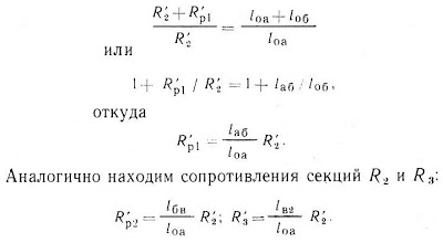
That is, the ratio of critical slip for artificial characteristic 2 and natural characteristic 1 is equal to the ratio of the reduced active resistance of the rotor phase, including the resistance of the starting rheostat section, to the reduced active resistance of the rotor.
It can be seen that for any identical moments for the natural and artificial characteristics the condition s / s kp = const holds, therefore, for characteristics 1 and 2 at the moment M = M p, the equality

On the start-up diagram (see Fig. 5), sliding s 1 corresponds to the segment "oa", and sliding s 2 corresponds to the segment "about". We denote the length of the first segment l oa, the second l oa + l about, then:
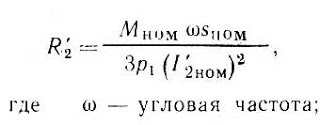
The active resistance of the motor rotor winding is determined from the catalog. If there is no data on resistance in the catalog, it can be calculated using the formula:
Electric braking. Methods for electrical braking of AC motors are similar.
Braking mode with energy return to the network occurs at a rotor speed exceeding the frequency of rotation of the magnetic field. This mode is possible when the motor accelerates under the influence of a falling weight or when the multi-speed electric motor is switched to a lower speed.
When the engine accelerates under the action of a falling weight according to the natural characteristic 0 (Fig. 6), the rotation frequency increases and at M = 0 it reaches the rotation frequency of the magnetic field n x. With further acceleration of the engine, the rotational speed becomes more than n x, more than the mains voltage and the machine operates in the generator mode, giving active energy to the mains. The characteristic section in quadrant II corresponds to this mode.
Dynamic braking of an induction motor is performed by disconnecting the stator winding from the three-phase supply network and turning it on from a direct current source (Fig. 7), while a stationary magnetic field appears in the motor instead of a rotating magnetic field (n x = 0). As a result of the interaction of a rotating rotor with a stationary magnetic field, a braking torque occurs (see Fig. 6, characteristic 1). The braking torque can be adjusted by changing the DC voltage or by changing the resistance of the resistor R (see Fig. 7).

Rice. 6-7. Mechanical characteristics asynchronous machine at different operating modes (6). The scheme of dynamic braking of an asynchronous electric motor (7)
For motors with a wound rotor, in addition, the regulation of the braking torque is possible by changing the resistance of the resistors included in the rotor circuit.
Opposition braking can be obtained by reversing the motor on the fly by switching two phases of the stator winding, while the magnetic field begins to rotate in the opposite direction and decelerates the motor. In fig. 6, this mode corresponds to a section of characteristic 2 located in quadrant II. When the engine speed decreases to zero, it must be turned off, otherwise it will start to rotate in the opposite direction (characteristic section 2 in quadrant III).
Comparison of braking methods
Comparing different ways of braking AC motors, it can be concluded that the most economical is braking with energy return to the network, but with it it is impossible to brake the engine to a speed lower than the speed of the magnetic field.
Dynamic braking allows you to brake the electric motor to a speed close to zero, but requires an additional DC source.
Opposite braking is least effective, since at high braking currents, the braking torque on the shaft of a squirrel-cage motor is negligible.
Therefore, this method of braking is used only for motors with a wound rotor, in which, due to the introduction of resistors with high resistance into the rotor circuit, it is possible to increase the braking torque while simultaneously reducing the current (see Fig. 6, characteristic 3).
contacts and we will instantly take all actions to remove your material.
⇓ DISCUSS THE ARTICLE⇓
In the past 10-25 years, there has been a clear trend towards the transition from DC drive to AC drive due to the improvement of the laws of control of AC motors and the development of power electronics.
The use of AC motors is due to their simplicity, low cost, increased reliability, significantly smaller dimensions and weight compared to DC motors. The disadvantages of speed control include the high complexity of the theory of AC machines and control algorithms embedded in the converting devices.
The most widespread are the following methods of controlling the angular speed of an induction motor: 1) rheostat; 2) a change in stator voltage; 3) switching the number of pole pairs; 4) a change in the frequency of the supply voltage, etc.
Rheostat regulation
The scheme for turning on the blood pressure with this method of regulation is presented below. Rheostat characteristics are obtained by introducing additional resistance into the rotor circuit. In this case, with an increase in resistance, the rigidity of the MX decreases.
Permissible range of speed regulation for this method
Since, then approximately
![]() ,
,
where is the relative magnitude of the change in speed; - the relative magnitude of the change in torque.
From the obtained formula it can be seen that with equal relative deviations of the angular velocity and the load torque, the control range. With a lower permissible angular velocity deviation, the range is even smaller.
Power losses during rheostat regulation are made up of variable losses, including losses in copper of the stator and rotor and in external resistors of the rotor circuit, and constant losses that do not depend on the load. The total constant motor losses remain approximately the same regardless of the load and motor speed.
Electromagnetic and mechanical power for blood pressure
![]() ; ,
; ,
from here it is possible to determine the losses in the rotor
It can be seen that the losses are proportional to the slip value and are distributed in proportion to the ratio of the resistances of the motor rotor and the additional resistance in the rotor circuit, so the motor with rheostat regulation can develop a torque equal to the nominal one.
The disadvantages of rheostat speed control are stepwise speed control and the use of additional equipment, low speed and large energy losses during regulation.
Regulation of the IM angular speed by changing the stator voltage
When the value of the first harmonic changes, the value of the critical moment changes while the critical slip is constant.
This change is achieved by using a thyristor voltage converter (TVC).
The maximum torque with decreasing voltage decreases in proportion to the square of the voltage:
 ,
,
where is the critical moment at reduced voltage; - undervoltage.
Fig. it can be seen that the speed control limits are very limited, even at fan load.
To expand the range, closed-speed automatic control systems are used, the structural diagram of which is shown in Fig. below. A speed sensor (BR) and a speed regulator are included in such an automatic control system, which receives the difference between the set and current speed values. At the output of the speed controller, a signal is generated that is fed to the input of the pulse-phase control system, which generates control pulses for the TVC. The peculiarity of such regulation is that all characteristics converge at the point of synchronous speed, therefore, the lower the speed, the higher the slip and the greater the loss in the motor. The mechanical characteristics of the motor with phase control in a closed speed automatic control system are shown in Fig. 5.11.
With this method of regulation, the engine can operate for a long time provided
The permissible moment can be found by equating the permissible losses to the nominal
![]() .
.
The curve for permissible heating torque is shown in Figure 5.11.
This method of regulation cannot be used for mechanisms operating in continuous operation with a constant load. The use of phase control turns out to be effective for mechanisms in which the static torque depends on the motor speed, for example, for drives of fans, pumps, compressors. This method is also applicable when the engine is running at reduced speeds for a short time relative to the entire cycle of work, for example, elevators. In this case, the overestimation of the installed engine power is small.
The advantage of phase control is the lower cost of the converter (TVC) in comparison with the frequency converter (FC) of equal power, which allows for these mechanisms to provide an acceptable quality of the technological process without additional costs.
5.4.3. Changing the number of pole pairs
From the expression for the angular velocity of blood pressure:
![]() ,
,
it is seen that speed regulation can be carried out by changing the number of pole pairs p motor stator windings. Since this value can only be an integer, the speed control turns out to be stepwise.
For this type of regulation, multi-speed IMs with KZR are manufactured. In the grooves of the stator core, either two independent windings are placed, or one pole-switchable.
There are two main switching schemes. The star / double star arrangement (fig. 5.12, I-II) provides constant torque control. It is advisable to use such a scheme in an electric drive with a constant load torque when the rotation frequency changes. The "star / star" circuit (Fig. 5.12, I-III) also gives a twofold change in the number of pole pairs, however, regulation occurs at a constant power, that is, when switching to a higher speed, the torque is halved. It is reasonable to use such circuits in drives where the moment of resistance is inversely proportional to the speed. The mechanical characteristics of the blood pressure when regulating the speed by changing the number of plus pairs are shown in Fig. below.
Multi-speed IMs were widely used in electric drives that allow stepwise speed control (drives of elevators, fans, machine tools). The advantage of this method is the preservation of high economic indicators during the transition from one speed to another, since at all stages of switching the stator winding, the efficiency and power factor of the motor remain practically unchanged. The disadvantages include greater complexity in comparison with conventional blood pressure, overestimated dimensions, high cost. In addition, the need to switch the stator windings to a different number of pole pairs requires an increase in the complexity of the switching equipment, which also leads to an increase in the price of the electric drive as a whole. Currently, this method is being supplanted by frequency regulation.
Frequency regulation of the speed of an asynchronous motor
The frequency method of regulating the speed of blood pressure is the prevailing and basic one. What is the reason for this? First of all, at present, the theory of AC machines has been developed, which made it possible to find the laws of AM control that are optimal from some positions. The development of industrial electronics made it possible to fully implement these laws in hardware.
There are scalar, vector control systems and direct torque control systems. The choice of the method and principle of control is determined by a combination of static, dynamic and energy requirements for an asynchronous electric drive.
The principle of scalar control of a frequency-controlled asynchronous electric drive is based on changing the frequency and current values of the modules of variable IM (voltages, magnetic flux, flux linkages and currents of the motor circuits). This principle is the most widespread due to the fact that it is characterized by the technical simplicity of measuring and regulating the AM variables, as well as the possibility of constructing open-loop speed control systems. The main disadvantage is the difficulty of implementing the desired laws of speed and torque regulation of the IM in dynamic modes.
The principle of vector control is associated both with a change in the frequency and current values of the AM variables, and with the mutual orientation of their vectors in a polar or Cartesian coordinate system. Due to the control of the position of the angles of the variables, this method provides complete control of the AM in both static and dynamic modes, which gives a noticeable improvement in the quality of transient processes in comparison with scalar control.
Direct torque control systems are a continuation and development of vector control systems. The task of direct torque control is to ensure a quick response of the electromagnetic torque of the motor to the control action. In contrast to vector control, where the change in torque is made by acting on the stator current, in a system with direct torque control, the controlled variable is the stator flux linkage.
Frequency converters designed for frequency-controlled IMs are subdivided by the type of connection with the mains into direct frequency converters (NFC) and two-link frequency converters (DFC) with an intermediate DC or AC link.
The AM moment is proportional to the magnetic flux and the active component of the secondary current:
![]() ,
,
where is the constructive constant blood pressure; - shear angle between EMF and rotor current;
 .
.
From the formula for the torque, it can be seen that a decrease in magnetic flux, which is a consequence of an increase in frequency, will lead to an increase, and therefore losses in the rotor, and a simultaneous decrease in the permissible engine torque under the conditions of engine cooling. A decrease in frequency with a constant voltage amplitude, as shown in Section 4.3.3, is also not permissible under the conditions of saturation of the magnetic system of the machine. Therefore, the regulation of the motor speed by changing the frequency of the supply voltage, provided that the motor torque is constant, is acceptable only with a simultaneous change in the amplitude of the supply voltage, that is, the law is fulfilled, which ensures an almost constant magnetic flux in the motor.
To implement the specified control law, a frequency converter (FC) is switched on between the network and the motor, providing a simultaneous change in the frequency and amplitude of the voltage on the motor. At lower speeds, self-ventilated motors reduce heat dissipation to the environment, therefore, in such cases, it is necessary to reduce the permissible torque on the motor.
With frequency control, for reasons due to the mechanical strength of the bearings and rotor elements, raise the frequency higher. Therefore, the main way to control the speed is to decrease the voltage frequency.
To construct an approximate form of mechanical characteristics, we assume that, then the equation for the critical moment can be rewritten as follows:
 .
.
It can be seen from the formula that the critical moment when the law is fulfilled remains constant. The condition of neglecting the active resistance of the stator is correct at high motor speeds, when. At low speeds the voltage drop across the active resistance of the stator becomes comparable to the voltage at the stator terminals, which leads to a drop in the overload capacity of the motor. In order to realize the same overload capacity with frequency control in the low speed range, the so-called " IR compensation», Which consists in the fact that at low speeds an addition of voltage is made on the stator, which compensates.
The speed control range in open systems is. In closed systems, the range can be significantly expanded.
The main difficulties arising in the implementation of frequency control are as follows:
1) to obtain properties similar to (or even superior) to those of TP-DPT systems in PCh-IM systems, it is necessary to obtain information on various parameters of IM;
2) the systems are highly nonlinear and in order to obtain high-quality systems, it is necessary to introduce links that compensate for the nonlinearity of the controlled object;
3) the law is not optimal, and an adjustment of the law is required, taking into account the motor shaft;
4) the IM includes parameters, the value of which depends on the degree of saturation of the machine nonlinearly. In addition, the values of the active resistances of the stator and rotor change when the temperature of the motor windings changes, which must also be taken into account.
Despite these difficulties, modern frequency drives operate successfully, providing high quality speed regulation process.
There are positions in electrical installations when a direct current electric motor is indispensable. It is this electric motor that can be adjusted according to the rotor speed, which is required in electrical installations. True, it has a lot of shortcomings, and one of them is the rapid wear of the brushes, if their installation was carried out with curvature, and their service life is quite low. With wear, sparking occurs, therefore, such an engine cannot be used in explosive and dusty rooms. Plus, the DC motor is expensive. To change this situation, an asynchronous motor and a frequency regulator for an asynchronous motor are used.
In almost all respects, AC motors are superior to DC counterparts. First, they are more reliable. Secondly, they have smaller dimensions and weight. Third, the price is lower. Fourth, they are easier to operate and connect.
But they have one drawback - it is the complexity of speed control. In this case, the standard methods for regulating the frequency of induction motors will not work here, namely, changing the voltage, setting the resistance, and so on. Asynchronous frequency control electric motor Was problem number one. Although the theoretical basis has been known since the thirties of the last century. The whole thing rested on the high cost of the frequency converter. Everything changed when microcircuits were invented, with the help of which it became possible to assemble a frequency converter through transistors with minimal cost.
Regulation principle
So, the way to control the speed of an induction motor is based on one formula. Here she is below.
ω = 2πf / p, where
- ω - angular speed of rotation of the stator;
- f is the frequency of the input voltage;
- p is the number of pole pairs.

That is, it turns out that it is possible to change the rotation speed of the electric motor only by changing the voltage frequency. What does this give in practice? The first is the smooth operation of the motor, especially when starting up the equipment, when the engine itself is operating under the highest loads. The second is increased slip. Due to this, the efficiency increases, and the loss of power characteristics decreases.
Frequency controller structure
All modern frequency converters are built on the principle of the so-called double conversion. That is, the alternating current is converted to direct current through an uncontrolled rectifier and filter. Further, through a pulse inverter (it is three-phase), the reverse conversion of DC current into AC current occurs. The inverter itself consists of six power switches (transistor). So, each winding of the electric engine is connected to certain keys of the rectifier (positive or negative). It is the inverter that changes the frequency of the voltage that is applied to the stator windings. In fact, it is through it that the frequency regulation of the electric motor takes place.

In this device, power transistors are installed at the output. They act as keys. If we compare them with thyristors, then it should be noted that the former produce a signal in the form of a sinusoid. It is this shape that creates minimal distortion.
Now the very principle of operation of the frequency converter. To understand this, we propose to disassemble the figure below.
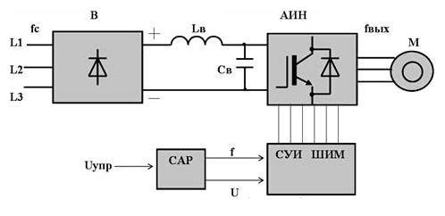
So, let's go through the picture, where
- "B" is a diode-type uncontrolled power rectifier.
- "AIN" is an autonomous inverter.
- "FMS PWM" is a pulse-width control system.
- "SAR" - automatic regulation system.
- "Sv" - filter capacitor.
- "Lв" - throttle.
The diagram shows very clearly that the inverter regulates the voltage frequency due to the pulse-width control system (it is high-frequency). It is this part of the regulator that is responsible for connecting the stator windings of the electric motor alternately to the positive pole of the rectifier, then to the negative one. The frequency of connection to the poles follows a sinusoidal curve. In this case, the pulse frequency is determined precisely by the PWM frequency. This is how frequency regulation happens.
The principle of operation of the DPT. There should be two main parts in the machine: the first part - creates a magnetic flux, the second part - in which the EMF is induced. The first part in the DC machine is stationary. Stamped poles (2) are attached to the frame (1) on which the field winding (3) is located. The second part is the anchor. The anchor rotates. It is a cylinder made of electrical steel sheets (4). In the outer part of the armature there are grooves where the winding sections (5) are laid. Each section is connected to manifold plates (6). 

The electromagnetic moment depends on the flux and armature current. In generator mode, the electromagnetic torque is braking. The equation of the equilibrium state of the moments will be written, where is the mechanical moment on the generator shaft, is the moment xx, and is the electromagnetic moment. The basic equation of motion of the electric drive. Steady state process when ,,, If ,,. If,,. 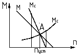
 The principle of speed control. In terms of speed control, the DC motor is versatile. You can adjust the speed by changing the resistance in the armature circuit, flux and applied voltage. This can be seen from the formula:.
Resistance in the armature circuit. Equations of currents before and after the introduction of resistance
Whence, i.e. currents, the moment decreases (). At the same time, the speed decreases. With a decrease in the speed of the armature, it increases, and it will reach the initial current of the armature, but at a lower speed. The control of the rotation frequency by the resistance in the armature circuit is carried out in the direction of decreasing the speed. 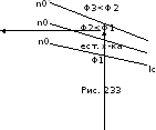
Stream. Armature current before and after flux change, their ratio. The equation 5.1. moments. Decrease the flow, The armature current has increased, then, then (increases).
Voltage. Speed control is performed in the following ways: A) Generator-engine system (G-D). B) Thyristor converter-motor (TP-D). C) Pulse-width regulation.
 A) G-D system, fig. 234. ... By increasing the excitation current of the generator i bg, the flux F g and E g increases, and therefore the voltage at the motor armature increases and the speed increases.
B) Thyristor converter-motor. Increasing the control angle - the half-period area decreases, the average voltage value -U cf decreases, and therefore the rotation speed decreases.
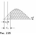
C) Pulse-width regulation.
By changing the pulse time t and the duty cycle changes, where t and is the pulse time; t p - pause time. Average value U cf = U 0 . ... 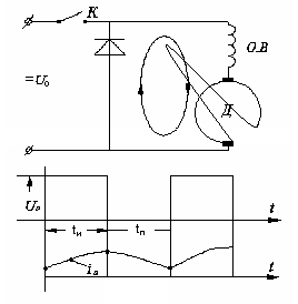
6. Methods for regulating the active and reactive power of a synchronous machine.
Methods for regulating the active and reactive power of a synchronous generator. As you just saw that if you change the excitation of the generator, then by doing so we will change the reactive power, give or consume. The active power can only be regulated by changing the mechanical power from the steam turbine or hydraulic turbine. With an increase in the output of active power, it is necessary to increase the mechanical power from the side of the turbine.
Start SD. to start a synchronous motor, it is necessary to accelerate its rotor using an external torque to a rotation frequency close to the synchronous one. Since there is no starting torque in a synchronous motor, the following methods are used for starting it: 1 Start with an auxiliary motor; 2 Asynchronous engine start.
1. Start-up of a synchronous motor by means of an auxiliary motor can be carried out only without mechanical load on its shaft, i.e. practically idle. In this case, for the period of starting, the engine is temporarily transformed into a synchronous generator, the rotor of which is set in rotation by a small auxiliary motor up to n = 0.95n 1. The stator of this generator is connected in parallel to the network, subject to the conditions of this connection. After connecting the stator to the network, with a short delay, the excitation winding is turned on, and the motor is pulled into synchronism, and the auxiliary drive motor is mechanically disconnected. This starting method is complex and also has an auxiliary motor.
2. A synchronous motor turns into an asynchronous motor during start-up. To enable the formation of an asynchronous starting torque, a starting short-circuited winding is placed in the slots of the pole pieces of a salient-pole motor. The process of starting a synchronous motor is carried out in two stages. When the stator winding (1) is connected to the network, a rotating field is formed in the motor, which will induce an EMF in the short-circuited rotor winding (2). Under the action of which the current will flow in the rods. As a result of the interaction of the rotating magnetic field with the current, a torque is generated in the short-circuited winding, like in an induction motor. Due to this moment, the rotor accelerates to a slip close to zero (S = 0.05), Fig. 313. This concludes the first stage. In order for the motor rotor to be pulled into synchronism, it is necessary to create a magnetic field in it by connecting a direct current to the excitation winding (3) (by switching the key K to position 1). Since the rotor is accelerated to a speed close to the synchronous one, the relative speed of the stator and rotor fields is small. The poles will smoothly find each other. And after a series of slips, the opposite poles will pull in and the rotor will pull into synchronicity. After that, the rotor will rotate at a synchronous speed, and its rotation frequency will be constant, Fig. 313. This concludes the second stage of the start-up. SD operation in under-excited and overexcited modes (ib=
var).
The operating mode corresponds to the constancy of the torque. at. With an underexcited synchronous motor, the voltage component -E 0 corresponds to the current I, which lags behind the voltage Uc by an angle φ. The reactive component of the current I L will lag 90 0 from the voltage vector Uc, i.e. this current is purely inductive. This means that when under-excited, the motor will consume inductive current from the network, and therefore will consume reactive power from the network. 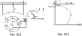
With increasing excitation, the value –E 0 1 will increase, and the current I will decrease to Ia = I 1 and will be minimal. In this mode, the LED will operate with cosφ = 1 and reactive power will neither be consumed nor supplied to the network. With a further increase in the excitation current, the voltage component will be equal to –E 0 11, and the current I 11, will advance the voltage vector of the network by an angle φ 1. This mode corresponds to the overexcited mode. The reactive component of the current will be capacitive (ahead of the vector Uc by 90 0). This mode will correspond to the output of reactive power to the grid. This mode is similar to the inclusion of static capacities in the network. 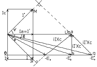

So we see that if we change the excitation current iB, then the value of the stator current I will change in magnitude and in phase, i.e. cosφ can be adjusted. It is this valuable property that determines the use of synchronous motors. The dependences of the stator current I on the excitation current iв, I = f (iв) are called U-shaped characteristics, Fig. 309. P 2> P 1. The characteristics are taken at P = const. The operating mode corresponding to the excitation current from 0 to the dotted line is under-excited, and behind the dotted line - overexcited with the return of reactive energy to the network.
In many cases, three-phase asynchronous motors are used for drives that do not require speed control. But induction motors have valuable advantages: reliability, low cost, simple design, high efficiency and relatively low weight. For these reasons, it is natural to strive to apply them to variable speed drives.
To control the speed of rotation of asynchronous motors with a squirrel-cage rotor, the frequency control method is usually used, which is a smooth regulation of the frequency of rotation of the magnetic field by regulating the frequency of the current in the stator windings, and the method of changing the number of pairs of poles of the rotating magnetic field, in which the frequency of rotation of the magnetic field changes leap.
To control the speed of rotation of induction motors with a wound rotor, the method of rheostat regulation is used, which is a smooth control of the slip "of the rotor by changing the active resistance of its phase windings.
Frequency regulation. The most promising method for controlling the speed of an induction motor is stator ac frequency control engine. The angular velocity of the rotating field is n = 2 f / p. Consequently, with a change in the frequency of the current f, the angular velocity of the field changes proportionally. However, when regulating the frequency of the current, it must be taken into account that it is necessary to simultaneously regulate the voltage. This is due to the fact that, in accordance with expression (14.10), the EMF of the phase, and hence the supply voltage, is proportional to the frequency of the current and the flux. Since the flux must remain the same in all modes, the voltage must be (excluding voltage drops in the machine) proportional to the frequency. In addition, this is necessary so that when the engine speed changes, its torque does not change.
To assess the nature of the dependence of the torque on the frequency of the current in the stator windings and on the voltage across it, we neglect in equation (14.28) the active resistance of the stator winding g l and inductive resistances of leakage of the stator windings x pac 1 and rotor x rac2 and use the expression for the slip frequency (14.13):
Mvr= = A,
where A= const.
Therefore, when changing the frequency of the current, to maintain the torque constant, it is necessary to proportionally change the voltage across the stator; in other words, the condition for maintaining the constancy of the motor torque during frequency control will be U 1 / f= const. If you regulate the frequency of the current and voltage, observing the specified condition, then the mechanical characteristics of the motor will remain rigid, and the maximum torque will be almost independent of frequency (it decreases significantly only at relatively low frequencies). At the same time, the power will change in proportion to the frequency of the current, since Р 2 = M vr r. For example, when the frequency of the current is reduced by 2 times, the motor power on the shaft is also halved.
Regulation by changing the number of pole pairs. A stepwise change in the angular speed of an asynchronous motor within a wide range is feasible at the cost of complicating and increasing the cost of the design of an asynchronous motor - this is regulation by switching the number of pairs of motor poles.
At a constant network frequency, the angular velocity of the rotating field depends only on the number of pole pairs of this field, determined by the stator winding. If two separate windings are placed on the stator - one forming R steam, and the other, forming R" pairs of poles, then by connecting the first or second winding to the network, we get the field rotation frequency:
N 1 = 60f / p or n "1 = 60f / p", hence,
n1 / n "1 = p" / p,
the rotational speed of the engine rotor will differ accordingly. In this case, the winding of the motor rotor must be made like a squirrel wheel.
The numbers of poles of the stator windings in this case are mutually unrelated and can be chosen any depending on the operating conditions of the motor. The regulation itself is reduced to an abrupt change in the rotational speed of the motor field. But the rotor speed cannot change abruptly due to the inertia of the entire electric drive system. Only after the changeover does the corresponding change in the rotor speed begin.
To show this transient process more clearly, we construct two mechanical characteristics of an asynchronous machine with a variable number of pole pairs: one characteristic corresponding to R pairs of poles, and the second p "= 1p pairs of poles (respectively Fig. 14.31, a and b). Let us assume that the torque on the motor shaft remains constant as the field rotational speed changes. When the latter increases, i.e., when passing from R" To R in pairs of poles, the motor first finds itself in conditions close to starting, and a current surge occurs.
But when going from R To R", that is, with a decrease in the frequency of rotation of the field, the machine first finds itself in a generator mode and works, giving energy to the network.
This mode is sometimes used for quick and economical braking of an electric drive.
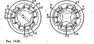
Stators are supplied with two separate windings only for low power motors; For high-power motors, it is more expedient to switch the coils of the same winding to obtain a different number of pole pairs. In fig. 14.32 shows a circuit for switching a three-phase winding from two to four poles. Switching the winding in a ratio other than 1: 2 requires more complex circuit changes and is less common.
In most cases, the stator of an induction machine is supplied with two independent windings, each of which switches in a ratio of 1: 2 or otherwise. Thus, the engine has four speed stages, for example 3000,> 1500, 1000 and 500 rpm.
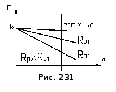
Rheostat regulation... In three-phase asynchronous motors with a wound rotor, a rheostat method is used to regulate the rotor speed. This is achieved by introducing an adjustable three-phase rheostat into the circuit of the phase windings of the rotor, as when starting the engine (Fig. 14.24). But this rheostat must be designed for a long-term load by the rotor current, and not for a short-term one, like a starting rheostat. An increase in the active resistance of the rotor circuit changes the characteristic M(s) - makes it softer (see fig. 14.25). If, at a constant torque on the motor shaft, the active resistance of the rotor circuit is increased by gradually increasing the resistance of the rheostat (r p1< rp2< r р3), то рабочая точка будет смещаться с одной кривой M (s) to the next one, corresponding to the increased resistance of the rotor circuit (Fig.14.25, points 1-4), accordingly, the slip will increase, and, consequently, the engine speed will decrease.
In this way, it is possible to change the rotor speed in the range from nominal to full stop. But with this method of regulation, relatively large energy losses are inevitable (see § 14.11). Rotating field power P bp, p without taking into account energy losses in the stator core, it consists (see Fig. 14.20) of the power losses in the conductors of the rotor winding (see the equivalent circuit in Fig. 14.19);
P pr2 = r "b2 (I" 2) 2
and mechanical power
R fur = r "b2 (I" 2) 2.
Attitude
R pr 2 / R fur = s / (l -s) = (n 1 - n) / n
shows that dividing the mechanical power decreases in direct proportion to a decrease in the rotor speed, at the same time, the share of power losses in the active resistance of the rotor circuit increases accordingly. Consequently, to reduce the engine speed, for example, by 25%, it is necessary to include a rheostat with such an active resistance in the rotor circuit, in which a quarter of the energy of the rotating magnetic field will be uselessly converted into heat. The disadvantage of such regulation may be the fact that the inclusion of a rheostat in the rotor circuit makes the mechanical characteristics of the engine softer, therefore, reduces the stability of its rotational speed. When the rheostat is on, small changes in the load on the shaft cause significant changes in the engine speed.