Let's start with the fact that we will mention that engine cooling systems are also different, I mean the differences in the principle of operation and device, as well as the expediency of using each of these systems in one or another branch of the automotive industry. We are talking about air and liquid cooling of motors.
The simplest type of engine cooling is of course air cooling. Take the engine of the T-40 tractor as an example. What we will see there, but nothing supernatural, everything is outrageously simple: a separate unit with a powerful fan, driven by a belt drive from the crankshaft pulley using a specially built path, during operation directs a powerful air flow to the ribbed engine liners, ribbed they are made like times for better heat dissipation. An oil cooler is also installed in the path of the same air flow to cool the oil. This method is called forced air, but as elsewhere it has its drawbacks: cooling only by a directed air flow cannot provide a constant temperature and it will jump up and down, which is not very good. Therefore, in order to avoid the engine wedge in case of short-term overheating on engines with forced air cooling, increased thermal clearances between the piston and the liner, as well as increased thermal clearances piston rings.
As an example, air-cooled engines are used in large numbers on motorcycles, I think many looking at a motorcycle engine hardly thought about its cooling system. Both forced air cooling and free air cooling are also used there. That is, the engine is not cooled by anything, but stupidly gives up its heat to the atmosphere, and when it moves, it is cooled only by the oncoming air flow. Imagine getting into a traffic jam on a motor with such a dvigl, it will have to be constantly turned off so that it cools down, then start to drive five meters and turn off again so as not to warm up while waiting. Most motorcycle motors, both boxer and simple, are made largely of aluminum, firstly because it is light, and secondly, it has good heat dissipation. Now, engineers are trying to install a liquid cooling system on modern motorcycle motors, since it is more stable and less susceptible to the risk of overheating. By the way, what is now installed on racing motorcycles as an engine could well be installed in some kind of Zhigulator, instead of a native motor.
Now let's consider a liquid engine cooling system using the simplest example. So, the main components of a liquid cooling system:
- The radiator is the main coolant reservoir of the cooling system.
- The jacket of the engine cooling system - cavities in the block and the cylinder head of the engine, which are filled with coolant.
- The thermostat is a small piece needed to keep the engine operating at a constant temperature.
- The pump - or pump of the water cooling system, is necessary to ensure the circulation of coolant between the radiator and the water jacket.
- Coolant temperature sensor - and so it is clear.
- System of pipes and hoses - required to connect the radiator and the water jacket of the engine block.
- Expansion tank - needed to eliminate coolant losses when it expands or boils.
Now let's try to understand how it all works. The main part of the coolant is in the radiator, water jacket and pipe system. The entire cooling system is built like a vicious circle with the help of channels in the block and the cylinder head, and this is all connected to the radiator. A water pump installed in a certain segment of the cooling circle circulates fluid when the engine is running. The pump is driven by the crankshaft, belt or gear drive, and the speed of rotation of the pump shaft directly depends on the speed of the engine crankshaft. That is, the higher the engine speed, the more it needs cooling, therefore, the pump rotates faster, driving and cooling large volumes of coolant than when the engine is running quietly.
The liquid cooling system is divided into a small cooling circle and a full cycle. This is necessary to ensure faster engine warm-up and maintain engine operating temperature during cold seasons. The small circle provides cooling of the engine bypassing the radiator. This is achieved through the use of a thermostat, which helps to warm up the engine faster. After the engine is warmed up, the thermostat opens and cooling occurs already in a full cycle, that is, the coolant already passes through the radiator.
Maintenance and repair of the engine cooling system. Here, in principle, there is nothing complicated, you need to make sure that nothing leaks or gets wet anywhere, also watch the coolant level in the radiator and its color. Suppose you have red antifreeze filled in, if you suddenly notice that it is no longer red but orange, this is a sure sign that it needs to be replaced. Remember that antifreeze and antifreeze are also not eternal, and need to be replaced at least once every two years. But be careful, recently, motors have been repaired, the cooling system of which seemed to run on acid, aluminum parts were eaten from the inside, huge sinks on cast iron, there were several cases when the unit became unusable, I am sure that all this is due to homemade antifreeze and antifreeze, before, when engines were cooled with ordinary water, this was not the case.
Appointment and schemes.
Cooling system serves to maintain optimal thermal conditions of the engine by means of controlled heat removal from the hottest parts.
The high temperature of the gases during the working stroke causes intensive heating of parts in direct contact with hot gases ( cylinders, cylinder heads, pistons, valves). Heating of engine parts requires 20 - 35% of the heat released during the combustion of fuel in the cylinders. If this heat is not removed, that is, the engine is not cooled, oil will burn out on many moving parts and, due to excessive expansion, they will seize. To avoid overheating of parts, heat is forcibly removed from them with an intensity that depends on the mode and operating conditions of the engine. With insufficient heat dissipation, the engine overheats - it does not develop maximum power, fuel consumption increases, and engine parts wear out quickly due to insufficient lubrication. In the event of excessive heat dissipation, i.e. when the engine is overcooled, its fuel efficiency also deteriorates and the service life is significantly reduced.
Therefore, the engine should be cooled to the optimum temperature that ensures maximum power and high efficiency, as well as a long service life (motor resource).
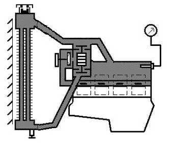
Forced heat removal in engines can be carried out using liquid (liquid cooling system) or air (air cooling system). On car engines most widespread liquid cooling systems, since they are more efficient in operation compared to air-cooled systems, they create less noise and provide better engine start at low temperatures. A schematic diagram of a liquid engine cooling system is shown in the figure. Around cylinders 77 of the engine and their heads, there is a space (cooling jacket) filled with coolant. Cooling jacket connected nozzles 8 and 15 s radiator 2 - a device serving to cool the heated liquid. The radiator and jacket are filled with liquid through the filler neck, which is closed stopper 5. The plug has valves through which the inner cavity of the cooling system communicates with the atmosphere. Such cooling system called closed. In closed cooling systems, an overpressure (up to 100 kPa) is maintained, as a result of which the boiling point of the coolant rises to 120 ° C. Steam is discharged by tube 4. Closed cooling systems are more compact than open ones, that is, they directly communicate with the atmosphere, and less often need additional filling with coolant.
Forced circulation of fluid in the system is created pump 14, brought into operation from crankshaft engine pulley 7. The liquid comes into contact with the heated walls of the cylinders and the head, heats up and through pipe branch 8 enters the upper radiator reservoir. On the tubes radiator 2, blown by a stream of air, the liquid passes into the lower radiator tank and is cooled. Air movement through the radiator is ensured fan 6 and the pressure of the oncoming air flow when the vehicle is moving. Chilled liquid through pipe branch 75 enters and from the pump through the water distribution pipe 12 is brought back to the hottest parts of each cylinder. The water distribution pipe allows uniform cooling of all parts, regardless of their distance from the pump. Thus, in the cooling system there is a continuous coolant circulation.
The coolant temperature is controlled by thermometer 13. The optimum engine temperature is one when the temperature of the coolant in the cylinder head is 80 -100 ° C. To quickly warm up the engine, especially after starting it, a thermostat 10. When the engine is cold, the thermostat valve is closed and the liquid from the cooling jacket cannot enter the radiator (into the large circulation circle). When the thermostat valve is closed, liquid flows to the pump through tube 9 (small circle of circulation). Since the engine in this case is cooled only by part of the fluid filling the system, this fluid heats up quickly. After that, the thermostat valve opens and the engine is cooled with all the liquid circulating in a large circle. The flow area of the thermostat valve and the amount of liquid entering the radiator increase as the temperature rises, than the temperature of the engine is automatically regulated within certain limits.
The optimal temperature regime of the engine is maintained mainly by changing the intensity of the air flow passing through the radiator. With help blinds 3 change the amount of air passing through the radiator and thus the cooling rate. The air flow rate can also be changed using a fan with automatically variable blade pitch. On some engines, the fan is turned on only after the engine has warmed up. The liquid is drained through tap 1 installed at the lowest point of the cooling system.
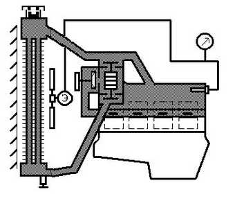
One of the features of the engine cooling system of a VAZ-21011 car (Fig.) Is the presence expansion tank 5 located at the highest point of the system. Expansion tank, vented, filled with coolant and connected tube 4 sec filler neck 3 radiator 1. When opening the outlet (steam) valve, which is equipped with the filler plug, excess liquid or steam is discharged into expansion tank... When the volume of the coolant decreases (for example, when it cools), the inlet valve opens in the plug and the liquid from the expansion tank returns to the radiator. Thus, the system maintains a constant volume of circulating fluid.
Another feature of the cooling system of this engine is the way to maintain optimal temperature regime provided by two-valve thermostat 2. When the engine is cold, the lower thermostat valve is closed and no coolant flows through the radiator. In this case, the liquid is pumped pump 11 in shirt 10 cylinder block and then in shirt 7 block heads. The liquid coming out of the front of the head of the block goes to the upper valve of the thermostat and enters the pump again. Due to the circulation of this part of the fluid, the engine warms up quickly. At the same time, a smaller part of the liquid enters from the head jacket into shirts 6 inlet pipe and mixing chambers of the carburetor, and when open tap 8 in radiator 9 interior heater.
When the engine is warm, the upper thermostat valve is closed, the lower one is open. In this case, most of the fluid from the head jacket enters the radiator 1, is cooled in it, and then on pipeline 12 and through the open bottom valve of the thermostat enters the pump. A smaller part of the fluid, as with a cold engine, circulates through the intake manifold, carburetor and interior heater. In a certain temperature range, both thermostat valves are open and the liquid circulates simultaneously in two circles. The amount of moving fluid in each circle of circulation depends on the degree of opening of one or another valve, which ensures automatic maintenance of the optimal temperature regime of the engine. There are no blinds in the engine cooling system of the VAZ-21011 car.
As coolants apply water or a special low-freezing liquid - antifreeze... Peculiarity antifreeze TOSOL consists in the fact that their boiling point significantly exceeds 100 ° C, and the inhibitors contained in them reduce the corrosion of all metal parts.
At air cooled of the engine, the cylinders and their heads are equipped with a large number of fins to increase the cooling surface. The cooling air is supplied by a powerful fan driven by the engine crankshaft. Air enters the cylinders through a guide casing, which ensures their uniform cooling. The heated air comes out through a special socket in which a damper is installed. When turning the damper, carried out by the driver or automatically, the cooling intensity changes, which ensures the optimal temperature of the engine.
The main advantages air cooling front liquid is its ease of use and the impossibility of failure of the system in cold weather.
Liquid cooling system design... The radiator is a heat exchanger in which the heat from the water is transferred to the air stream. In the upper cistern 6 (fig.) Radiator available neck 8 through which the system is filled with coolant. The neck is hermetically closed with a plug 7 equipped with two valves. Steam valve 3 (fig.), Pressed against the end necks 5 strong spring 4, opens to release steam from the system at an overpressure of 45-55 kPa. Air valve 2 having a weak spring 7, opens when the pressure drops to 10 kPa due to cooling of the liquid. 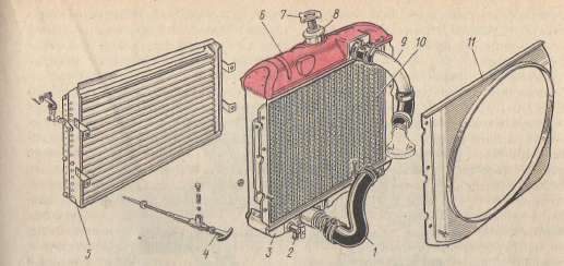
In the bottom cistern 3 (see picture) radiator installed tap 2 to drain fluid from the system. The upper and lower tanks are connected by rows of flat tubes with plates soldered to them, forming the required cooling surface. Both tanks, tubes and plates of such a radiator, called tubular-plate, are made of brass for better heat transfer. Sometimes basis 10 radiators are made tubular-tape. In order to increase the heat transfer area of such a radiator, corrugated tapes are laid between the tubes over the entire width of the frame. The coolant enters the radiator through pipe 9, and is removed from it through pipe 1. The radiator is fixed to the vehicle frame in front of the engine with rubber cushions. 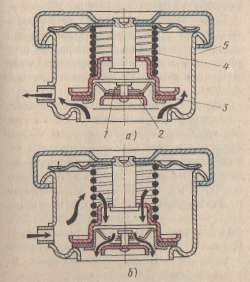
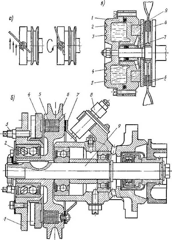
The centrifugal type liquid pump circulates the liquid in the cooling system. The housing of the liquid pump of the ZIL-130 engine consists of two parts - a cast-iron housing 4 (Fig.), Bearings and an aluminum corps 5 impellers. Shaft 10 pump rotates in two ball bearings 8 and 9 equipped with oil seals to retain lubricant. At one end of the shaft there is a plastic impeller 6 with metal hub. The impeller is equipped with a self-tightening stuffing box 7, a rotating textolite washer of which is pressed by a spring against the highlander of the bearing housing. The self-tightening gland prevents fluid from escaping from the pump. On the other end of the shaft there is hub 1 fluid pump drive and fan 2. Bolted to the hub with a three-strand pulley 3.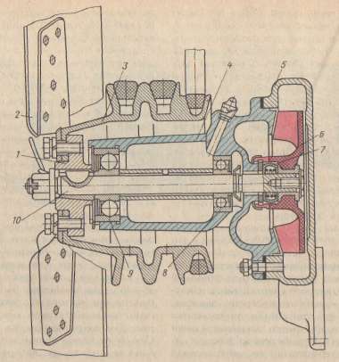
The fluid pump and fan are driven V-belt transmission... The crankshaft pulley is connected with two belts pulley 3 driving the liquid pump and fan. When the pump shaft rotates, the liquid enters the center of the impeller, is captured by its blades and, under the action of centrifugal force, is thrown to the impeller housing, where it is collected in a special channel (snail) and is directed to the outlet pipe. At an engine speed of 3000 rpm, the pump flow is 240 l / min. Effective engine cooling achieved only with normal drive belts tension.
Thermostat is an automatic valve that helps to accelerate engine warm-up and regulates the amount of fluid passing through the radiator within certain limits.
Thermostat 10 (Fig., A) is installed in branch pipe 8 at the liquid outlet from the cooling jacket. Thermostats are available with liquid and solid fillings. The solid-filled thermostat has a 1 thick-walled cylinder filled mixture 2 ceresin (petroleum wax) with copper powder. There is a guide above the cylinder sleeve 4 with a hole for the stem 5. The sleeve is separated from the cylinder by a rubber membrane 3. The stem is connected yoke 9 sec flap 7 (valve).
When the engine is cold, the throttle is closed and no coolant flows into the radiator. When ceresin is heated, it melts, its volume increases, as a result of which membrane 3, buffer 11 and stock 5 move up, the spring 6 is stretched and damper 7 opens. The liquid begins to circulate through the radiator (high circulation rate). The thermostat damper begins to open at a coolant temperature of (70 + - 2) ° С, the damper (Fig., B) opens completely at a temperature of (83 + - 2) ° С.
In the range of these temperatures, the area of the thermostat passage opening increases with increasing temperature, as a result of which the amount of liquid entering the radiator automatically increases. 
In liquid-filled thermostats, the sensitive element - a corrugated cylinder made of thin brass - is filled with an easily evaporating liquid (a mixture of distilled water and ethyl alcohol). When the cooling system is cold, the cylinder is depressurized and compressed, closing the thermostat valve. When the liquid in the thermostat cylinder heats up to a certain temperature, its pressure rises so much that the cylinder expands and the thermostat valve opens. Thermostats with a solid filler have greater mechanical strength compared to thermostats with a liquid filler, which allows them to be used in closed cooling systems with high excess pressure (ZIL-130 engines).
Fan serves to increase the speed and amount of air passing through the radiator. The fan is usually installed directly behind the radiator. Fan blades 2 (see figure) are riveted to hub 1. The fan supply depends on the diameter, number and angle of inclination of the blades, as well as the frequency of rotation of its shaft. On domestic automobile engines, fans have four, six or eight blades. The blades are made of sheet steel or plastic. The angle of inclination of the blades to the plane of rotation is 35 - 40 °. To improve the efficiency of the fan, it is sometimes placed in a guide casing 11 (see figure) fixed to the radiator. For the same purpose, the ends of the blades are bent towards the radiator. On some motors, rotation from the shaft to the fan blades is transmitted by an electromagnetic clutch. When the engine is cold, the clutch automatically disconnects the blades from the shaft, accelerating engine warm-up.
Blinds 5 turn with radiator 4, as a result of which the air flow rate through the radiator changes and this maintains the thermal regime of the engine. On some car engines, the blinds are controlled automatically.
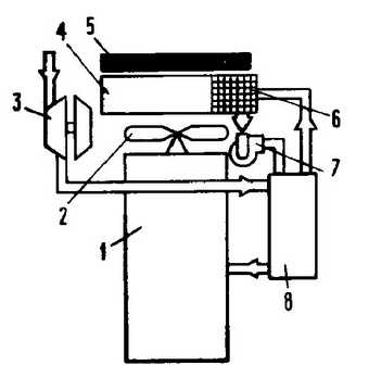
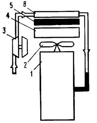
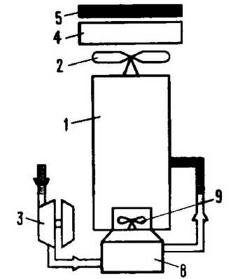
Preheater(fig.) provides engine heating before starting at low temperatures. Along with the ease of starting, preheating the engine helps to slow down the wear of parts, especially cylinders and pistons.
In the set preheater are included boiler 7, connected with a hose filler funnel 3; fuel tank 4, from which fuel enters the boiler through an electromagnetic valve 8; fan 5 with an electric motor; Remote Control 7 and glow plug 10.
Before starting the engine, the boiler connected to the cooling jacket of the cylinder block is filled with water. The solenoid valve enters the combustion chamber of the boiler, where it initially ignites candle 10. Air is supplied to the boiler from fan 5 to hose 6. Hot gases passing through the gas pipelines of the boiler heat the water, and when leaving the boiler nozzle 11 are sent to the engine oil pan, heating the oil in it. The water is heated in the boiler and, due to convection, enters the cooling jacket of the cylinder block along hose 9, and returns to the boiler by hose 2.
The cooling system is designed to forcibly remove excess heat from the engine parts of the car and transfer it to the surrounding air. Engine cooling is used to forcibly remove heat from heated parts to ensure optimal thermal condition of the engine and its normal operation.
The temperature during the engine operating cycle varies from 80-120 ° C (minimum) at the end of the intake to 2000-2200 ° C (maximum) at the end of the combustion of the mixture.
If the car engine is not cooled, then the gases that have a high temperature will greatly heat the engine parts and they expand... The oil on the cylinders and pistons burns out, their friction and wear increase, and from excessive expansion due to overheating of parts, the pistons become jammed in the engine cylinders, and the engine may fail. To avoid the negative phenomena caused by overheating of the motor, it must be cooled.
but excessive cooling of the engine adversely affects its performance... When a car engine is overcooled, fuel (gasoline) vapors condense on the cylinder walls, washing off the lubricant, and dilute the oil in the crankcase. In these conditions, there is an intense wear of the piston rings, pistons, cylinders and the efficiency and power of the engine decreases. Normal operation of the cooling system helps to obtain the most power, reduce fuel consumption and increase the life of the car engine without repair.
Most of the heat removed is absorbed by the cooling system, less - by the lubrication system and the immediate environment.
Due to this, a certain temperature regime is created at which the engine does not overheat and does not overcool... Heat in automobile and tractor engines is removed in two ways, depending on the type of coolant used: liquid (liquid cooling system) or air (air cooling system). These systems absorb 25-35% heat generated during fuel combustion. The temperature of the coolant in the cylinder head should be 80-95 ° C for non-pressurized cooling systems and up to 126 ° C for pressurized cooling systems. This temperature regime is the most beneficial, ensures the normal operation of the engine and not should change depending on ambient temperature and engine load.
Liquid cooling system automotive engine (Fig. 1) consists of a water jacket, radiator, fan, thermostat, pump with impeller, outlet and inlet pipes, fan drive belt, fluid temperature gauge sensor, drain valves and other parts. There is a double-walled space (water jacket) around the engine cylinders and cylinder head where the coolant circulates.
During the operation of the car engine, the coolant is heated and is pumped into the radiator of the cooling system by a water pump, where it is cooled, and then again enters the jacket of the cylinder block. For reliable engine operation, it is necessary that the coolant constantly circulates in a closed circle: engine - radiator - engine. The liquid can circulate through small circle, bypassing the radiator (cold engine, thermostat closed), or big circle, entering the radiator (warm engine, thermostat open).
The engine water jacket consists of a cylinder block jacket and a cylinder head jacket, interconnected by holes in the gasket between the cylinder head and the block. The impeller of the water centrifugal pump and the fan are driven by a drive unit. When the pump impeller rotates, coolant is pumped into the water distribution pipe located in the block head. Through the holes in the tube, the liquid is directed to the exhaust valve pipes, thereby cooling the hottest parts of the block head and cylinders. The heated liquid flows into the upper outlet pipe. If the thermostat is closed, the liquid flows back to the centrifugal pump through the bypass. When the thermostat is open, the coolant flows into the upper radiator reservoir, cools by flowing through the tubes, and enters the lower radiator reservoir. The liquid cooled in the radiator is supplied to the pump through the lower inlet pipe,
The water pump pumps fluid into the cooling system, and its main flow passes through the water jacket of the cylinder block from its front to the rear. Washing the cylinder liners from all sides and passing through the holes in the mating surfaces of the cylinder block and block heads, as well as in the gasket located between them, the coolant enters the cylinder head shirts. At the same time, a significant amount of coolant is supplied to the hottest places - the exhaust valve pipes and the spark plug sockets. In the heads of the block, the coolant moves in the longitudinal direction from the rear end to the front due to the presence of holes of the corresponding diameter drilled in the mating surfaces of the cylinder block and heads, and metering inserts installed in the rear channels of the intake manifold. The hole in the insert limits the amount of fluid entering the intake manifold jacket. Warm liquid passing through the jacket of the intake manifold heats up the fuel mixture coming from the carburetor (through the inner ducts of the pipeline) and improves mixture formation.
The temperature of the liquid in the cooling system is monitored with a remote thermometer, the receiver of which is located in the driver's office on the instrument panel, and the sensor in the water distribution box (diesel of a KamAZ car), in the water channel of the intake pipeline (engines of GAZ and ZIL cars), in the head of the block (engine of a GAZ car -24 "Volga"). If the water temperature in the cooling system exceeds a certain value, then a warning lamp on the instrument panel lights up, for example, red at a water temperature of 105-108 ° C.
Air cooling system automobile and tractor engines consists of a number of elements that regulate its operation and maintain a given thermal state of the engine.
The schematic diagram of air cooling includes the engine compartment, which is covered by the corresponding body panels; axial or centrifugal fan with guide vanes driven from the engine crankshaft; cooling jacket guides, as well as air flow controls, such as thermostat-controlled dampers that choke the air inlet or outlet, or an automatic fan speed control clutch. An oil cooler is placed in the cooling air flow. To monitor the thermal state of the engine, a temperature sensor and an indicating device in the driver's cab are used.
The simplest air cooling system - the pressure of the oncoming air is used for motorcycle engines... The uniformity of cooling is achieved both by the appropriate shape of the ribbing and by the installation, in some cases, of the guide plates.
The most common fan systems use two schematic diagrams cooling air supply: with blower fan and suction fan.
The blower fan operates in a stream of colder and denser air, has a higher flow rate and requires less energy. The less economical suction fan provides more uniform cooling of the cylinders without complicated guides and distribution baffles.
To maintain optimal thermal conditions of the engine, the amount of air supplied to the system is regulated. The simplest options are to throttle the air flow in the system using manually or thermostatically controlled dampers.
Each of these cooling systems has Advantages and disadvantages.
TO the benefits of liquid cooling should include:
more efficient heat removal from heated engine parts at any thermal load;- fast and uniform warming up of the engine during start-up;
admissibility of using block structures of engine cylinders; - less prone to knocking in gasoline engines;
- more stable thermal state of the engine when changing its operating mode;
- lower power consumption for cooling and the possibility of using heat energy rejected into the cooling system.
disadvantages liquid cooling systems:
- high maintenance and repair costs in operation;
- reduced reliability of engine operation at negative ambient temperatures and greater sensitivity to its change.
TO advantages of the air system cooling include the following:
simplicity and ease of use due to the lack of liquid;- Lighter weight of the air-cooled engine compared to the weight of a similar liquid-cooled engine;
- reduced sensitivity to temperature fluctuations, especially valuable when operating a car in areas with hot or cold climates.
TO disadvantages Air cooled engines include the following:
significant power consumption for the fan drive;- some deterioration in the filling of the cylinder, leading to the fact that at the same crankshaft speeds and other parameters, an air-cooled engine develops slightly less power than a liquid-cooled engine;
- increased noise during operation;
- high thermal stress of individual parts.
The liquid cooling system is most expedient to use in forced engines and in engines with a relatively large working volume of the cylinder; air cooling system - in engines with a cylinder displacement of up to 1 liter, regardless of the degree of boost, and in engines with a small liter capacity.
CLASSIFICATION OF ENGINE COOLING SYSTEMS
Most car engines have liquid cooling systems (open or closed). In an open cooling system, the interior is directly connected to the surrounding atmosphere. Closed cooling systems have become widespread, in which the internal space only periodically communicates with the environment using special valves. In these cooling systems the boiling point rises coolant and reduces its boil-off.
The specific amount of heat removed into the cooling medium depends on the dimensions of the cylinders and the ratio of the piston stroke to the cylinder diameter, which affect the relative areas of the heat-receiving and cooled surfaces.
With an increase in engine power by 25 - 68% as a result of the use of pressurization, the specific amount of heat decreases by 3 - 15%.
The efficiency of heat removal from the walls into the cooling medium is the greater, the lower the viscosity of the medium and the higher its density, thermal conductivity and heat capacity.
With air cooling, the rate of heat removal from the walls decreases even more.
So, when the water and air are stationary relative to the walls and with the same temperature differences, the heat transfer coefficients differ by a factor of 30, when moving at a speed of 1-3 m / s water and 50 m / s air they differ by 13-15 times.
At boiling water, the rate of heat transfer exceeds the rate of heat transfer to the air by about 40 times... Therefore, to ensure the permissible temperatures of parts of air-cooled engines, the ratio of the areas of surfaces that receive heat from gases and give it to the cooling air is increased up to 14 times by ribbing the outer surfaces.
Separate cooling of heads and cylinders allows to increase engine efficiency up to 4% and power up to 5%.
The main controlled parameter of the cooling system is the temperature of the coolant at the engine outlet, measured using temperature sensors and remote thermometers. Temperature sensors are usually installed at the coolant outlet from the engine cooling system or units, for example, turbochargers.
By regulating the operation of cooling systems, it is possible to significantly reduce the temperature variation of parts, their joints, seals, depending on the operating conditions of the engines. For this, it is most expedient to regulate the operation of the cooling systems so that the temperature of the cooling body at the exit from the shirts or underhood spaces (or the entrance to them) remains constant.
This is ensured by the following:
regulating the amount of body supplied to the cooling system (in air cooling systems);- a change in the amount of heated coolant directed by thermostats to the coolers;
- a change in the intensity of liquid cooling in coolers;
- by a combination of several control methods, for example, by changing the amount of liquid cooled in coolers and the intensity of cooling in them.
The second controlled parameter is the pressure of the cooling medium in the cooling system.
Air pressure together with its flow rate determine the power consumption for the fan drive; it is not controlled, since it directly affects the design and performance of cooler grilles, deflectors and casings.
In closed liquid cooling systems, due to vaporization when the engine overheats, an increase in pressure is possible; In high temperature water cooling, overpressure is created to increase the boiling point. Therefore, closed systems are always equipped with so-called pressure-limiting steam valves to prevent possible destruction of cylinder and block jackets, pipelines, coolers, expansion tanks, as well as loss of tightness of connections, in particular, cylinder liner seals and cylinder bushings.
When the engine is switched off or the load is reduced, on the contrary, due to condensation of vapors in the system, a vacuum can be created and there is a risk of destruction of the elements of the cooling systems by ambient pressure. To eliminate this, closed systems are equipped with air valves that allow air to enter the system. Typically, steam and air valves are combined into a steam-air valve, made in one body. This housing is often a device that closes the filler hole located at the top of the system - the pipe that connects the engine to the chiller, cooler, expansion tank, or mixing tank.
With the method of regulation by changing the amount of the working fluid supplied to the cooling surfaces or coolers, the greatest distribution was obtained axial fans.
The supply of axial fans is changed by periodically switching off the fans using frictional or electromagnetic clutches or by continuously changing the fan rotor speed using electric motors mounted in the fan, electromagnetic clutches and, most often, using hydraulic couplings integrated into the fan drive mechanism.
In the event of an interruption in the supply of oil to the fluid coupling, it is blocked, and the fan rotates at the speed of the shaft. Depending on the filling of the volumes between the blades of the pump and turbine wheels through the oil supply pipe to the fluid coupling, the rotation frequency of the turbine wheel and the fan changes from 0 to 95 - 98% of the shaft rotation frequency. At the same time, the water temperature is maintained within 80-95 ° C, depending on the engine operating mode. The amount of oil supplied to the fluid coupling is automatically controlled according to the outlet water temperature.
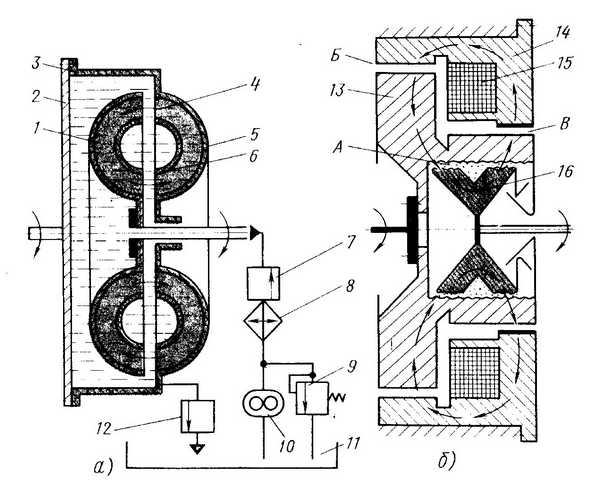
a) 1- driven part, turbine wheel; 2- cover; 3-leading part, pump wheel; 4- blades; 5, 6 - outer and inner torus; 7- filling valve; 8- radiator; 9-safety valve; 10- pump; 11- tank; 12- emptying valve. b) A, B, C - gaps; 13- leading part; 14-stationary body; 15- excitation winding; 16- driven part.
With the method of regulation by changing the intensity of cooling the liquid in liquid-air coolers, the intensity of cooling the liquid is controlled by changing the cooling surface with various shutters, curtains and aprons-seals or the supply of fans pumping air through the cooler grill.
In the method of regulation by changing the amount of heated coolant, devices are used that allow changing the direction of movement of the liquid and its flow through the cross-section of the supply pipes, thermostats.
 Rice. 6 Thermostat diagram.
When the engine is cold, the thermostat valve is closed and the liquid from the cooling jacket cannot enter the cooler (into the large circulation circle). When the thermostat valve is closed, the liquid flows to the pump through a small circulation circle. When the liquid heats up, the thermostat valve begins to open and the engine is cooled by all the liquid circulating in a large circle. The flow area of the thermostat valve and the amount of liquid entering the cooler increase as the temperature rises, than the temperature regime of the engine is automatically regulated within certain limits.
Thermostats are available with either one valve or two valves and are used in various cooling systems.
With the combined control method, all of the above methods are used in various combinations. They received the greatest distribution in modern engines, since they allow you to maintain the most optimal temperature regime.
Depending on the method of liquid circulation, cooling systems are subdivided into thermosyphon, with forced circulation of liquid and mixed.
In a thermosiphon cooling system, circulation is carried out due to the difference in density between cold and hot liquid. During engine operation, the liquid in the cavity of the cooling jacket heats up and enters its upper zone, from where it enters the upper radiator tank through a branch pipe. In the radiator, the liquid gives off heat to the air, its density increases, as a result of which, due to natural convection, it again enters the cooling jacket. For intensive circulation of liquid in such systems, a significant temperature difference (about 30˚) is required at the inlet to the radiator and at the outlet from it.
In systems with forced circulation, the liquid is pumped from the radiator to the lower zone of the cooling jacket, that is, to the zone that does not require intensive heat removal, and then it is supplied to cool the hotter head. The temperature difference at the inlet and outlet of the radiator in such systems can be within 8-12˚, which makes it possible to significantly reduce its dimensions.
Mixed cooling systems are characterized by the fact that cold liquid from the radiator is pumped into the upper area of the cylinder cooling jacket or directly into the cylinder head cavity. In this case, the cylinders are cooled by natural convection of the liquid, which makes it possible to maintain the temperature of their walls at the desired level. Coolant is supplied to the hottest walls of the combustion chamber and exhaust pipes in such systems, often through special water distribution pipes or channels. The temperature of the liquid at the exit from the engine is maintained within 80-95˚ regardless of the operating mode by means of a thermostat that restricts the circulation of coolant through the radiator, louvers that close the radiator grill, or by adjusting the fan performance. The interior heater is also connected to the cooling system, in which the coolant circulates.
The periods of regulation of the cooling system are distinguished:
One-cycle cooling system engine.
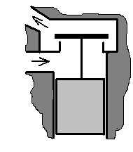
This cooling system lacks thermostats and various fan drive clutches. The coolant always circulates through the cooler and the cooling intensity is regulated only by changing the cooling surface with various louvers, curtains and aprons-seals.
 Rice. 7 One-cycle cooling system.
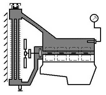
Two-cycle cooling system engine.
This cooling system uses single-valve thermostats that allow you to change the direction of flow and the amount of coolant. During the first regulation period, when the thermostat valve is closed, the water circulates in a small circle. Since the engine in this case is cooled only by part of the fluid filling the system, this fluid heats up quickly. In the second period of regulation, the thermostat valve opens, and the engine is cooled by all the liquid circulating in a large circle.

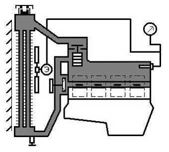
Three-period engine cooling system.
In this cooling system, two-valve thermostats or single-valve thermostats are used together with changing the fan operating mode using various couplings and electric motors. In the first control period, water circulates in a small cooling circle, with the thermostat valve closed. In the second period, the coolant circulates both in a small and a large cooling circle with the valves of the two-valve thermostat open, or in a large cooling circle with a single-valve thermostat. In the third control period, the liquid circulates in a large cooling circle with a two-valve thermostat, and with a single-valve thermostat, the fan drive is turned on.
 Four-cycle cooling system.
It is used with a two-valve thermostat. The first three regulation periods are similar to those described above, and in the fourth regulation period, the fan drive is turned on.
Cooling systems and the additional listed elements included in them have filler and drain holes that are closed with plugs or taps. Drainage devices are located at the lowest points of the system sections and are used to drain not only coolants, but also flushing fluids, with the help of which deposits and scale are removed.
In installations with motors internal combustion The heated coolant is often used to heat cabins or other rooms, for which cooling systems are connected to heating systems.
To quickly warm up liquid-cooled engines before starting, preheaters are installed in the cooling system: with gasoline burners or diesel fuel steam or water, powered by external sources of thermal energy (car engines with garage-free storage of cars).
COOLING SYSTEMS
Cooler.
Heat dissipated into the cooling liquid of the internal circuit (water, TOSOL, antifreeze) and lubricating oil as well as the heat received during the cooling of the charge air is transferred to the coolant in the respective coolers.
Cooling medium in installations land transport is atmospheric air.
In this case, when atmospheric air is used to dissipate heat, heat exchangers are called radiators.
The expediency of using one or another coolant can be characterized by the following relative values of heat transfer.
The use of charge air coolers for automotive engines does not significantly change the basic layout of the cooling system. However, the type of charge air cooler (water or air) and its design are largely determined by the overall design of the main cooling system.
Water radiators used to cool the charge air and installed in systems with an autonomous liquid low-temperature circuit (Fig. 11, a), work in the same way as the main radiators for cooling water. In some cases, they are performed in one block with the main water radiator of the engine.
Air radiators included in the air path of the main engine cooling system (Fig. 11, 6) are usually installed in front of the water and oil coolers, and they are washed by air, the temperature of which differs little from the ambient temperature. The external and internal cooling surfaces of such radiators are performed taking into account the difference in the conditions for heat transfer of air flows under increased (charge air) pressure. A significant drawback of this scheme is the increased hydraulic losses during the cooling of the charge air, which can be an order of magnitude (or more) higher than in the system made according to the scheme in Fig. 11, a.
Systems, the diagram of which is shown in Fig. 11, c, and used on some diesel engines of the YaMZ family.
The following requirements are imposed on the materials used in coolers for internal combustion engines:
sufficient strength and ductility,- high thermal conductivity,
- resistance to corrosion,
- manufacturability and low cost.
From the point of view of meeting these requirements, the most suitable materials for the manufacture of heat exchangers are copper, aluminum and their alloys. Steel water radiators, in comparison with copper ones, have a large mass, low thermal conductivity and insufficient corrosion resistance. The use of protective zinc coatings does not provide reliable anti-corrosion protection for radiators. Therefore, steel is usually used almost exclusively for the manufacture of oil coolers.
 Rice. 11a) b) c) Schemes for installing a cooler on automotive engines.
1- engine; 2- main fan; 3- pressurization unit; 4- water radiator; 5- oil cooler; 6-section water radiator for charge air cooling; 7-auxiliary water pump; 8- charge air cooler; 9- auxiliary fan
Water radiators used to cool the charge air and installed in systems with an autonomous liquid low-temperature circuit (Fig. 11, a), work in the same way as the main radiators.
For the manufacture of heat exchangers, copper grades Ml, M2 and MZ are used, containing copper (according to GOST 859-78) in the range of 99.9 - 99.5%. On the basis of copper, various alloys are obtained that have high mechanical and technological properties, for example, an alloy of copper with zinc.
The lightest and most promising material is high-purity aluminum (such as ADO or AD1); aluminum-manganese alloy (AMts type); an alloy of aluminum with magnesium (AMg type). However, aluminum and alloys based on it have insufficient resistance to erosion and corrosion in comparison with copper and its alloys. Therefore, bimetallic materials are preferred to monometallic aluminum materials, in which the surface in contact with an aggressive environment is made of a material that is resistant to erosion and corrosion, and the outer side is made of an aluminum alloy.
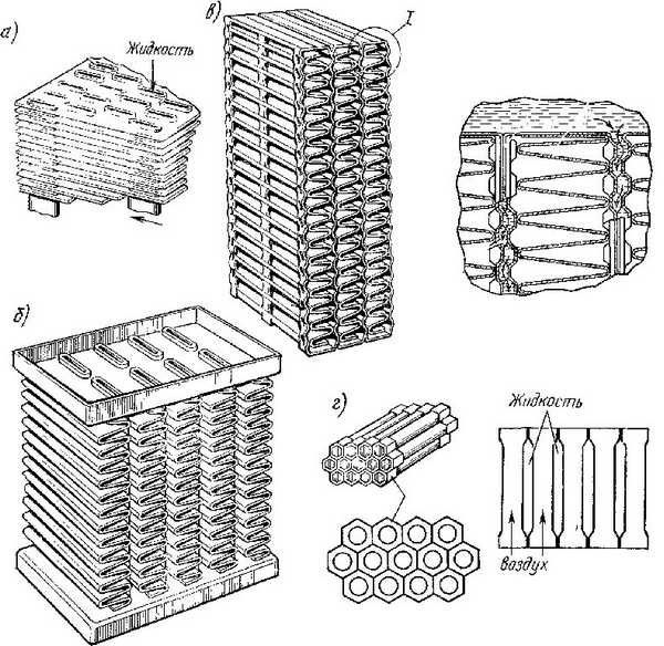 Rice. 12 Radiator grilles tubular-plate (a); tubular-tape (b); lamellar (c); cellular (g).
Currently, the most widespread are water radiators with tubular-plate-type cooling surfaces with a corridor or staggered arrangement of pipes.
Low mechanical strength (internal pressure up to 0.05 MPa) so far hinders the widespread use of water radiators with plate-ribbon type of cooling surface, although they have high compactness and thermal efficiency. In tubular-plate and tubular-tape radiators, thin-walled pipes of flat oval section are used. In tubular-plate radiators, round pipes are also used. The pipe wall thickness, depending on the material (steel, brass, copper, aluminum), ranges from 0.1 to 1 mm. In these radiators, the rational values of the pipe pitch are in the range of 10-18 mm - along the front and 21-24 mm - in depth. These dimensions allow for better utilization of the weight and volume of the radiator. The spacing of the finning plates in the radiator designs is 3-6 mm. Water radiators have a depth of three to six rows of pipes. Due to the increase in the degree of turbulence of the air flow when it moves through the first rows of pipes in a multi-row radiator, the heat transfer coefficient in the second and third rows increases compared to the first row, and then stabilizes. In radiators, the elementary channels through which the cooling air moves have different cross-sectional shapes: rectangular, square, triangular, semicircular, etc.
For cars and light trucks, the radiator depth is 60-90 mm. The calculated air velocities ahead of the radiator front are determined by the fan supply and for tractor engines can be 6-15 m / s. For automobile engines, the speed of movement is also taken into account. vehicle on lowest gear... This addition is 3-5 m / s. The speed of the water in the ducts affects the heat transfer in the radiator to a lesser extent than the speed of the air. Moreover, when a certain value of the water velocity in the channels (1.4 m / s) is reached, the heat transfer on the inner side of the cooling surface does not at all limit the heat transfer process in the radiator. A further increase in the speed of the water only leads to an excessive increase in the pressure drop in the radiator, and therefore the power expended to drive the water pump. The rational value of the water velocity is in the range of 0.4-0.8 m / s. The water temperature at the radiator inlet is 355-365 K. The water temperature difference in the radiator is 5-8 K. To prevent the formation of steam locks in the fuel supply line gasoline engines and ensuring the maximum average logarithmic temperature difference, the heating of the air in the radiator should not exceed 10-15 K. But during operation, as a result of the influence of air humidity, the heating of the air in the radiator can reach 40 K.
A radiator having an upper and lower reservoir connected by a radiator core. A filler neck, closed with a stopper, and a branch pipe for connecting a flexible hose supplying coolant to a radiator are soldered into the upper tank. On the side, the filler neck has an opening for a steam pipe. A branch pipe of the discharge flexible hose is soldered into the lower tank.
The side posts are soldered to the upper and lower tanks, connected by a plate soldered to the lower tank. The struts and the plate form the frame of the radiator. The radiator is connected to the engine cooling jacket by branch pipes and flexible hoses, which are attached to the branch pipes with clamping clamps. This connection allows for relative displacement of the engine and radiator. Louvers are installed in front of the radiator to regulate the amount of air passing between the radiator tubes. When the handle, fixed in the bracket, is moved forward to failure, the flaps open completely, and air flows freely between the radiator pipes.
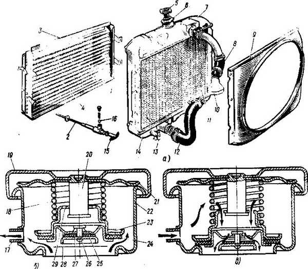
a -general form radiator b - the steam (outlet) valve is open; in - air (inlet) valve is open - / - rack - 2 - draft; 3 -frame; -/-blinds; 5 - radiator plug; b and 22 - radiator neck; 7 - upper reservoir; 8 and 12 - flexible hoses; 9 - guiding casing; 10 - branch pipe - // - radiator core; 13 - radiator drain cock; 14 - lower tank; 15 - blinds drive handle; 16 - retainer; 17 - vapor outlet tube; / "- the spring of the steam valve - / 9-plug body; 20 - rack; 21 - locking spring; 23 - steam (exhaust) valve; 24 - the gasket of the exhaust valve; 25 - air valve gasket; 26 - air valve; 27-spring of the air valve; 28 - air valve seat; 29 - hole for air intake
In the case of moving this handle back to failure, the doors close, and the air flow to the radiator stops. To maintain a certain temperature regime of the engine, the handle can be installed on the retainer in any intermediate position.

1- air valve; 2- steam valve; 3-steam outlet pipe
The throat is hermetically sealed by a plug that isolates the engine cooling system from the environment. The radiator plug consists of a body, steam and air valves and a closing spring. On the post, with which the locking spring is attached to the body, a steam valve is installed, pressed by the spring. The air valve is spring pressed against the seat pressed into the steam valve. A tight connection of the valves is achieved by installing rubber gaskets. If the rubber gaskets are damaged or destroyed, the cooling system becomes open and the water boils at 100 ° C.
If the liquid in the cooling system boils, the vapor pressure in the radiator increases. With an increase in pressure to 145-155 kN / m2 (1.45-1.55 kgf / cm2), the steam valve opens, overcoming the resistance of the spring. The cooling system of the engine is in communication with the environment, and the steam is released through the steam pipe. After stopping the engine, the liquid is cooled, the vapor condenses and a vacuum is created in the cooling system. When the pressure drops by 1 - 13 kN / m2 (0.01 - 0.13 kgf / cm2), the air valve opens and air begins to flow into the radiator through the holes and the valve, passing through the steam pipe. The operation of the steam and air valves prevents possible damage to the radiator from both external and internal pressure.
Tubular-plate radiators are widely used on tractors, combines, towing vehicles, trucks high carrying capacity, i.e. where it is necessary to ensure high mechanical strength.
On passenger cars, as well as trucks (low and medium carrying capacity), tubular tape radiators are installed, which have a slightly lower mechanical strength, but a relatively higher thermal efficiency and better manufacturability.
To cool oil in combined internal combustion engines, two types of coolers are mainly used - water-oil heat exchangers and air-oil radiators.
Water-oil heat exchangers are currently used in diesel engines of motor-tractor type of high power, since they are simple, compact, well-assembled on engines, reliable in operation, easily repaired and have smaller dimensions and weight compared to air-oil radiators.
For high-performance diesel engines in tubular-tape oil radiators, internal inserts - swirlers are used, which makes it possible, with the same core dimensions, to increase heat transfer by 2.7-3 times compared to smooth-tube oil radiators.
The turbulence inserts are freely inserted or soldered to the inner surface of the pipes. They are selected to provide an optimal balance between heat transfer efficiency and pressure loss.
Currently, aluminum air-oil radiators have become widespread, in which heat transfer per unit mass is 4-4.5 times higher than in brass ones.
Oil coolers of automotive engines are made of steel flat-oval pipes with a cross-sectional area of 17.5 x 5 mm with collective fins. The advantages of such radiators are simplicity of design, high reliability and low cost.
A centrifugal pump is used to create forced circulation of liquid in the cooling system. On Volga, ZIL-130 and other vehicles, water pumps are structurally combined with fans and have a common drive. The water pump (Fig. 15), mounted on the front end of the cylinder block, consists of a cast iron housing and an impeller housing. The shaft and fan rotate on ball bearings pressed into the housing.
![]()
The ball bearings are held against misalignment by a bushing and retaining rings. The ball bearings are sealed to retain the lubricant and to protect against contamination. A plastic impeller is bolted to one end of the shaft. On the other end of the shaft there is a split taper bushing and, on a key, the hub of the pulley and fan.
The shaft is sealed in the housing by a self-tightening gland consisting of a graphitized textolite washer, a rubber cuff, a spring and two clips. The oil seal rotates with the impeller, since the protrusions of the textolite washer enter the slots of the impeller shank. The spring through the rubber cuff presses the washer to the ground plane of the body, which prevents fluid from flowing out of the pump. The ball bearings of the pump are lubricated with grease that is not washed out by water. Before filling the bearing cavity with grease, unscrew the plug that closes the control hole. Through an oiler, grease is pumped into the pump housing with a syringe until it starts to come out of the control hole. After that, the plug 10 is screwed into the control hole.
Fan.
A fan, consisting of an impeller and a hub with a pulley, is used to create an air flow that cools the liquid flowing through the radiator tubes. Sometimes a guide casing (diffuser) is attached to the radiator frame for more intensive cooling of the liquid in it, inside which the fan blades rotate. The fan drive consumes up to 3-5% of the engine power, which causes an increase in fuel consumption. The increased noise of the engine is also associated with the fan. Therefore, at present, they strive to ensure the efficient operation of the cooling system with minimal energy costs. Fan operation is characterized by a pressure ratio, which is 0.07 for conventional single-stage axial fans with a small number of blades. For multi-blade axial fans, the efficiency is doubled (K = 0.15); axial-radial fans with a fixed guide vanes (K = 0.3) are even more efficient. Centrifugal fans (K = 0.4) work most efficiently. However, they are practically not used for liquid cooling systems due to the bulkiness of the air-collecting scroll.
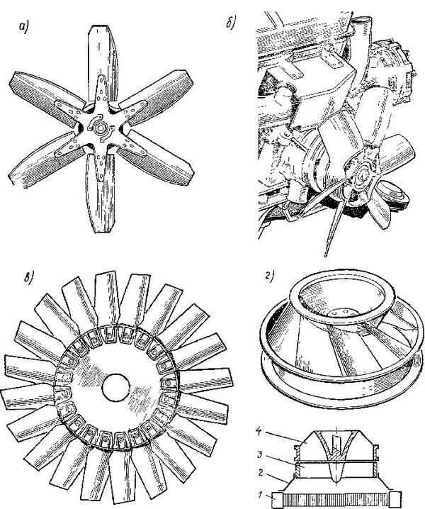
Axial fans are usually made with an uneven blade pitch, which reduces vibration and fan noise. In fig. 16a shows a simple six-blade fan with stamped steel blades. Now more often they use 6 - 8-blade fans, cast entirely from aluminum or plastic, the blades of which have a wing section (Fig. 16 b).
In fig. 16 c shows a multi-blade fan, assembled from short profile blades separately stamped from plastic, in Fig. 16 g - axial radial fan. The last two types of fans have high efficiency and are used on engines operating with high loads on machines with limited travel speeds. For engines passenger cars operating mainly with partial loads, subcooling is more relevant, therefore, fans with a supply that is controlled depending on the temperature of the coolant have now become widespread. When the coolant temperature is less than 85-90˚, they are disabled, which reduces fuel consumption.
 Rice. 17 Methods for changing the fan supply by changing the angle of attack of the blades (a), by turning off the fan (b, c).
Fans of engines of cars GAZ-53A, ZIL-130, etc. have blades with ends bent forward. When such a fan rotates, the air supply increases and the radiator cools better.
In the 60s, fans appeared with an angle of attack of the blades that decreased with an increase in the rotational speed of the engine shaft, that is, with an increase in the speed of the car and the dynamic pressure of air on the radiator grill.
The most common fan drive is V-belt transmission from a pulley on the toe of the crankshaft. The V-belt drive is quite simple, but it also has its drawbacks.
First of all, these are power losses due to belt deformation and low durability. Such a drive requires regular monitoring of the belt tension. Insufficient tension is associated with slipping and increased wear, and excessive tension is associated with overloading of the fan hub bearings. A more technologically sophisticated, but less "energy-intensive" gear fan drive was retained on YaMZ-236 engines. For small passenger car engines, the fan drive is increasingly used by an electric motor.
The required temperature of the liquid in the cooling system is automatically maintained by the thermostat. It allows you to quickly warm up cold engine at start-up. Automotive engines use thermostats with liquid and solid fillers. An easily evaporating liquid (a mixture of 70% ethyl alcohol and 30% water) is poured into liquid thermostats. Ceresin with copper shavings, which has a high coefficient of volumetric expansion, is used as a solid filler.
Liquid thermostat(Fig. 18 a) consists of a body with windows, a corrugated cylinder and a valve. The lower part of the corrugated balloon is rigidly connected to the bracket and the body. A stem with a valve is soldered to the top of the cylinder. The stem can move in the body guide. Sometimes a small hole or squeeze is made on the thermostat valve to allow air to escape when pouring fluid into the cooling system. A sealed corrugated cylinder contains a liquid that occupies approximately half of the internal volume of the cylinder. Air is evacuated from the cylinder, and under normal conditions it is compressed, and the valve is closed.
The liquid thermostat works as follows. If the temperature of the liquid in the cooling system does not exceed 73 ° C, then the cylinder is compressed and the valve is closed. The liquid flows through the bypass to the pump, bypassing the radiator. As the engine warms up, the fluid in the cooling system heats up. When its temperature rises above 73 - 83 ° C, the liquid in the cylinder begins to evaporate, the pressure in the cylinder rises and the valve opens. The coolant flows into the radiator. At a temperature of 88 - 94 ° C, the thermostat valve is fully open.
Solid filler thermostat(Fig. 18 b) is located between the inlet pipe and the outlet pipe. The valve is constantly pressed against the body by a spring, which is pivotally connected to the stem. The latter rests on a rubber membrane, which is sandwiched between the cylinder and the guide sleeve. The inner space of the balloon is filled with a solid filler. Until the engine is warm, the filler in the cylinder is solid and the thermostat valve is closed. When the temperature of the water in the cooling system rises to 70 ° C or more, the volume of the filler increases, since the ceresin melts and presses on the membrane. It bends upwards, presses through the buffer on the stem, which turns the valve, as a result of which the coolant enters the radiator. When the coolant temperature drops, the volume of the solid filler decreases, and the thermostat valve is closed by the return spring.
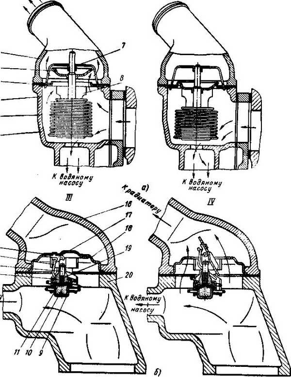
a - liquid (engine of a GAZ-24 car); b - with a solid filler (car engine ZIL –130; I - IV - thermostats are open; II - III - thermostats are closed; 1 - water pump housing; 2 - corrugated cylinder; 3 and 13 - rods; 4 - gasket; 5 and 15 - thermostat valves; 6 - 16 - hot liquid outlet pipes; 7 and 18 - thermostat housings; 8 - thermostat bracket; 10 - solid filler; 11 - rubber membrane; 12 - guide sleeve; 14 - return spring; 17 - valve shaft; 19 - buffer; 20 - inlet pipeline
BIBLIOGRAPHY
1. Car. Ed. A.N. Ostrovtseva. - M., mechanical engineering, 1976
2. N.N. Vishnyakov, V.K. Vakhlamov, A.N. Narbut. Automobile. Fundamentals of design, M.: Mechanical Engineering, 1986
3. Mikhailovsky E.V., Serebryakov KB, Tur E.Ya. Vehicle device. M.: Mechanical Engineering, 1981.
4. Ilarionov V.A., Morin M.M., Sergeev N.M. Theory and design of automobiles, Moscow: Mechanical Engineering, 1979.
It's no secret that the internal combustion engine heats up seriously during operation. Therefore, it constantly cools down. Today, there are liquid and air systems that help cool the internal combustion engine. Each of these systems is structured in its own way and has its own positive and negative aspects.
Liquid cooling
This method is the most widespread. This happened because during cooling Car internal combustion engine more favorable ones are created. In addition, a car equipped with a fluid system can be equipped with an internal combustion engine with replaceable parts from cheaper materials. This kind of cooling is much quieter than the other. Reducing the volume of work occurs due to the fact that the entire system provides double walls, as well as a layer of liquid.
Closed-type liquid cooling is equipped with a special device called, in which a level sensor is installed. It's not a secret for anyone that water evaporates during boiling, and coolants increase in volume. Based on this, the expansion tank was invented. Actually, there is nothing special in the device itself, this is an ordinary container for removing excess liquid that is formed during operation.
The peculiarity of the tank lies in the lid with which it closes for tightness. The fact is that a special valve is installed in this cover, which regulates the pressure in the engine cooling system.
It is provided so that when heated, the allocated volume does not independently seek a way out of the sealed system, but leaves through an automatically opening valve. This valve is activated when the motor is cooling down. The pressure decreases during the cooling of the motor, and in order to normalize it, this valve opens and returns air to the line. There are tanks on which there are two lids, one is responsible for air intake, and the second for the release of excess air.
The liquid type includes not only an expansion tank, but also a sensor. Devices such as: thermostat, metal and plastic connectors, sensors, radiator, pump and jacket; are also part of it. The cooling jacket refers to the channels that are located in the cylinder block and in its head.
The principle of reducing the temperature of this system is based on the fact that the liquid flows through all channels forcibly using the main pump. Due to the fact that the liquid is constantly in motion, the car engine reduces the temperature evenly, this is monitored by sensors. This is a significant advantage of this type of engine cooling system, therefore, modern cars such devices are installed. The heated liquid enters the radiator, where it reduces the temperature due to the air that enters the radiator while driving. When the car is stationary, the cooling of the liquid in the radiator occurs due to the operation of the fan, which is activated by a signal from the temperature sensor.
The cooling system of an internal combustion engine of this type has a number of advantages, the main of which is a uniform decrease in the temperature of the entire car engine. The system also reduces the volume of the engine due to the thickness of the block walls and the presence of liquid. The fact that the fluid is constantly circulating does not allow the engine to cool down quickly in winter. The heated liquid heats up the car interior and also heats up the fuel for the first start of the car (if an autonomous heater is installed).
In addition, this principle of operation of the engine cooling system has disadvantages, the main of which is tightness. The disadvantage is that it only works under pressure, which should ensure tightness. The tightness must be constantly maintained in proper condition, but this is complicated by the fact that temperature loads are constantly imposed on the rubber pipes. The fact is that all the parts are constantly heated, including the sensor, after which they cool down, and the rubber at this time is exposed to temperature loads, which leaks, and the tightness is broken. In addition to all this, almost all elements are responsible for the temperature of the liquid, and if at least one of the sensors becomes unusable, the entire system is overheated.
A more detailed scheme of work can be viewed by finding it at the appropriate request. After it is considered, it will be easier to understand the whole principle of operation.
Air
There are also air cooling systems for an internal combustion engine, which also has a sensor. This system, however, has lost its popularity for a long time. This type was in demand in the sixties of the last century.
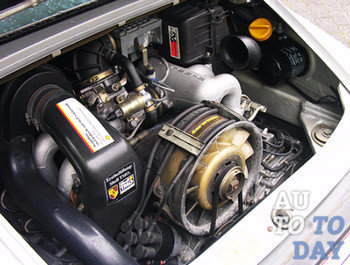
Most famous cars air-cooled are considered Porsches. The cars of this brand, thanks to the thoughts of Ferdinand Porsche, were equipped with the most powerful air-cooled engines of the time with a temperature sensor.
For a long time, the Porsche 911 was produced with an air cooling system. In the USSR, cars were also produced with this principle of lowering the engine temperature. During the entire existence of the USSR, the Zaporozhye Automobile Plant produced cars with this type of temperature reduction.
Today this view is not popular due to the fact that today all more cars equipped with an engine in the front. Such an engine is installed transversely, which allows a radiator to be installed. With this arrangement, it is difficult to properly adjust the air cooling and it is easier to install an air cooling radiator.
The principle of operation is based on the fact that the main fan supplies the required amount of air to the system, which cools the engine. Due to the fact that the cylinder block and the head heat up more than other components and mechanisms, most of the cooled air is directed at them. Air circulation in this system is automatically controlled by a thermostat and special dampers.
On the Internet, you can examine the circuit in detail and understand in more detail the whole principle of operation of such cooling. On the diagrams on the Internet, all devices that are part of the entire cooling line are shown and signed.
Despite the fact that the system has lost its popularity, it has several advantages. The main of them is the simplicity of the design, the weight of the car engine is also reduced, and the start of a cold engine is simplified. There are also disadvantages here.
The main disadvantage is the volume and increase. This type of cooling has many requirements for vehicle operation. Requirements are imposed on fuel, it must be of good quality, otherwise overheating cannot be avoided. Everything lubricants and spare parts must also be of high quality, the fact is that this type of temperature reduction works in extreme conditions all the time. In addition to all this, you need to monitor the cleanliness in the engine compartment, even a small layer of dirt on the car engine will lead to overheating.
Mixed
There is another type, a combined set of devices, which helps to reduce the temperature of heated elements. The principle of this complex is based on the fact that it combines all the advantages of both types. Combined cooling is most often installed on more powerful engines that are exposed to higher temperatures.
Summing up
Each system has a number of advantages and disadvantages. Depending on the type of car, certain engine cooling systems are installed on it, which have different designs and sensors. Each has its own principle of operation, which is different from the principle of operation of another system. In order to prevent the car's temperature from exceeding, you need to monitor all units and take care of it in time and properly.
Which system to install on the car is up to the manufacturer and you should not change it yourself. The factory-installed unit for lowering the engine temperature has a purpose specifically for this, if something does not work correctly, then all devices should be checked for operability.
For normal engine operation, a temperature of 80 - 90 degrees is required. And the temperature in the cylinder in working condition can rise up to 2000 degrees, which has a devastating effect on the parts. The cooling system in the car allows the engine not to overheat in the heat and freeze in frost. Violation of the temperature regime is fraught with rapid wear of parts, increased consumption fuel and oil, a drop in engine power.
In this way, the cooling system controls the temperature limits for ideal vehicle performance.
Purpose of air cooling
The direct purpose of the cooling system is to maintain the optimum temperature for engine operation. The cooling system is also responsible for heating the air in the cabin, for cooling engine oil and working fluid automatic gearbox, sometimes the intake manifold and the throttle assembly are cooled. As a result of fuel combustion, 35% of the heat is dissipated.
Did you know?The first cooling system appeared in 1950.
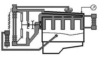
How the air cooling system works
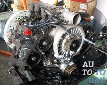 The name speaks for itself - the air flow is the main one in the air cooling system. With air, heat is removed from the cylinders, the head of the block and the oil cooler. The whole system consists of a fan (driven from the crankshaft pulley by a belt), cooling fins of the cylinders and head, a removable casing, deflectors and control devices. The fan has a protective mesh to prevent foreign objects from entering.
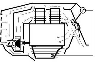
The air flow is forced to the engine by means of aluminum fan blades. Air moves between the cooling fins, and then it is evenly distributed with the help of deflectors to all parts of the motor.
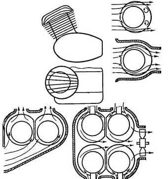
The fan consists of a directing diffuser (it has fixed radial blades of variable cross-section around the circumference to direct the air flow) and a rotor with 8 radial blades. The diffuser blades change the direction of the air flow, and it moves in the direction opposite to the rotation of the rotor. This increases the air pressure and cools the engine better.
Interesting to know!In 1997, an air-cooled engine was installed with two turbines in 400 Horse power... It is considered to be the most powerful.
 To increase the surface area for contact with air, additional ribs are installed on the cylinder block and cylinder head. The fan can supply 30 cubic meters of air per minute, which allows the engine to operate at temperatures from –40 ° to + 40 °. Thermostats and dampers allow you to adjust the cooling intensity of the engine.
Natural air cooling
The simplest way to cool an engine is natural air cooling. On the outer surface of the cylinders there are ribs through which heat is transferred. This cooling system is installed on motorcycles, mopeds, piston engines and etc.
Forced air cooling
The forced air cooling system has a fan and cooling fins. A shroud covers the fan and fins. This promotes the direction of the air flow and prevents the penetration of heat from the outside.
Advantages and disadvantages
Advantages air-cooled engines:
1. Simplicity of design. Easy to repair.
2. Low weight.
3. Reliability.
4. Inexpensive.
5. Good cold start performance.
Disadvantages:
1. Creates noise.
2. The size of the motor is increased.
3. Uneven airflow and local overheating.
4. Sensitivity to the quality of fuel, oil and parts.
Attention! Even a thin layer of dirt on the motor housing will reduce the cooling performance. Therefore, you need to carefully monitor the cleanliness of the engine housing.
Common breakdowns
 The sensor shows an increase in the oil temperature in - the cooling system is malfunctioning. Stop the engine immediately and investigate the cause. On dashboard the lamp lights up, which signals a malfunction. The reason may be a broken fan belt. It is very rare that there are problems with the thermostat.
Where are air cooled engines used?
Engines with an air cooling system are used less and less (they are being replaced by liquid cooling) in mechanical engineering (compact subcompact cars, diesel internal combustion engines, trucks, agricultural machinery).
Subscribe to our feeds in