Drive shaft, radians per second. Take the value of engine power from the technical characteristics in its passport. As a rule, the number of engine revolutions per minute is also indicated there.
Convert engine RPM to radians per second by multiplying the original number by a factor of 0.1047. Substitute the found numerical values into formula (1) and calculate the diameter of the drive pulley (node).
Calculate the diameter of the driven pulley using the formula: D2 = D1 u (2), where: - u - gear ratio; - D1 - calculated according to the formula (1) the diameter of the leading node. Ratio determine by dividing the angular velocity of the drive pulley by the required angular velocity of the driven unit. Conversely, for a given diameter of the driven pulley, its angular velocity can be calculated. To do this, calculate the ratio of the diameter of the driven pulley to the diameter of the driving pulley, then divide by this number the value of the angular velocity of the driving unit.
Find the minimum and maximum distance between the axes of both nodes by the formulas: Аmin = D1 + D2 (3), Аmax = 2.5 (D1 + D2) (4), where: - Аmin - minimum distance between the axes; - Аmax - maximum distance; - D1 and D2 - diameters of the driving and driven pulleys. The distance between the axes of the nodes should not be more than 15 meters.
If you cycle it in 3 minutes, then your speed is 167 m / min.
By car in 1 minute, which means the speed is 500 m / min.

To convert the speed from m / min to m / s, divide the speed in m / min by 60 (seconds per minute).
So, it turns out that when walking, your speed is 100 m / min / 60 = 1.67 m / s.
Bicycle: 167 m / min / 60 = 2.78 m / sec.
Machine: 500 m / min / 60 = 8.33 m / sec.

To convert the speed from m / s to km / h - divide the speed in m / s by 1000 (the number of meters in 1 kilometer) and the resulting
how to correctly calculate the diameters of the pulleys so that the knife shaft of the woodworking machine rotates at a speed of 3000 ... 3500 rpm. Rotation frequency electric motor 1410 rpm (three-phase motor, but will be connected to a single-phase network (220 V) using a capacitor system. V-belt.
The diameter of the pulley, depending on the shaft speed and the linear speed of the pulley, is determined by the formula:
where D1 is the pulley diameter, mm; V is the linear speed of the pulley, m / s; n - shaft rotation frequency, rpm.
The diameter of the driven pulley is calculated using the following formula:
D2 = D1x (1 - ε) / (n1 / n2),
where D1 and D2 are the diameters of the driving and driven pulleys, mm; ε - belt slip coefficient equal to 0.007… 0.02; n1 and n2 - rotation frequency of the driving and driven shafts, rpm.
Since the value of the slip coefficient is very small, the slip correction may not be taken into account, that is, the above formula will take on a simpler form:
The minimum distance between the axles of the pulleys (minimum center-to-center distance) is:
Lmin = 0.5x (D1 + D2) + 3h,
where Lmin is the minimum center-to-center distance, mm; D1 and D2 - pulley diameters, mm; h is the height of the belt profile.
The smaller the center-to-center distance, the more the belt bends during operation and the shorter its service life. It is advisable to take the center-to-center distance greater than the minimum value Lmin, and make it the larger, the closer the value of the gear ratio to unity. However, to avoid excessive vibration, do not use very long belts. By the way, the maximum center-to-center distance Lmax can be easily calculated using the formula:
Lmax<= 2*(D1+D2).
But in any case, the value of the center-to-center distance L depends on the parameters of the belt used:
L = A1 + √ (A12 - A2),
where L is the calculated center-to-center distance, mm; A1 and A2 are additional quantities that will have to be calculated. Now let's deal with the values of A1 and A2. Knowing the diameters of both pulleys and the standard length of the selected belt, it is not difficult to determine the values of A1 and A2:
A1 = / 4, and
A2 = [(D2 - D1) 2] / 8,
where L is the standard length of the selected belt, mm; D1 and D2 - pulley diameters, mm.
When marking the plate for the installation of an electric motor and a device driven in rotation, for example, a circular saw, it is required to provide for the possibility of moving the electric motor on the plate. The fact is that the calculation does not give an absolutely accurate distance between the axes of the motor and the saw. In addition, it is necessary to ensure that the belt can be tensioned and compensated for its elongation.
Rice. 2. Configuration of the groove of the pulley for the V-belt: с - (-) distance from the center of gravity of the belt profile to the outer edge of the pulley; Dras - the estimated diameter of the pulley; b - width of the groove of the pulley on the outer diameter; Dnar - the outer diameter of the pulley; e is the height of the stream; 2s - outer diameter pulley thickness; ф - angle at the top of the stream
The configuration of the pulley groove and its dimensions are shown in Fig. 2. Dimensions, indicated in the figure by letters, are available in the annexes to the corresponding GOSTs and in reference books. But if there are no GOSTs and reference books, all the required dimensions of the pulley groove can be roughly determined by the dimensions of the available V-belt (see Fig. 1), assuming that
b = act + 2c * tan (f / 2) = a;
s = a / 2 + (4 ... 10).
Since the case of interest to us is associated with a belt drive, the gear ratio of which is not very large, we do not pay attention to the angle of coverage of the smaller pulley by the belt when calculating.
The taper angle of the pulley groove depends on the pulley diameter and the brand of the belt. It is clear that the smaller the pulley diameter and the thinner the belt, the more the latter deforms when bending around the pulley. The angles between the sides of the groove of the pulley, depending on the brand of the belt and the diameter of the pulley, are shown in table 3.
Table 3. Configuration of the pulley (angle between the sides of the groove) depending on its diameter and on the brand of the belt
Drive power is an important information when calculating a belt drive, therefore table 4 provides appropriate recommendations for choosing a belt for specific operating conditions.
As a practical guide, we will say that the material for the pulleys can be any metal. We also add that in order to obtain maximum power from a three-phase electric motor connected to a single-phase network, the capacitances of the capacitors must be as follows:
Cp = 66Rn and Cp = 2Cr = 132Rn,
where Cn is the capacity of the starting capacitor, μF; Ср - capacity of the working capacitor, μF; Рн - rated power of the engine, kW.
For V-belt transmission, an important circumstance that strongly affects the durability of the belt is the parallelism of the axes of rotation of the pulleys.
Transmitted power P = 6.14 kW,
operating conditions - normal,
rotational speed of the drive pulley n 1 = 1440 rpm,
gear ratio i = 2.4.
Belt type - rubber-fabric wedge, belt section -A.
Torque on the driving pulley:
The diameter of the smaller pulley is determined by the formula:
round to the nearest value in accordance with GOST 17383 –73 and finally d 1 = 125 mm.
Larger pulley diameter:
round to the nearest value in accordance with GOST 17383 - 73 and finally d 2 = 315 mm.
We clarify the gear ratio:
![]()
Deviation from the calculated: ![]() .
.
Center distance:
Pre-select the center distance equal to 300 mm. Then the length of the belt will be equal to:
 We round off the value according to the standard row, we get the belt length L = 1400 mm
We clarify the center distance:
Smaller pulley wrap angle:
Determine the number of belts:
According to GOST 1284.3–80 P 0 = 2.19 kW; C L = 1.06; C p = 1.1; C α = 0.95; C z = 0.95;
Pre-tensioning of the V-belt legs:
![]()
The force acting on the shafts:
Examination
![]()
![]()
Preliminary calculation of the gearbox shafts.
We will carry out preliminary calculations for torsion at reduced allowable stresses.
Drive shaft:
Outlet end diameter at permissible stress, taking into account the effect of shaft bending from belt tension, [τ 0] = 25 MPa
![]()
We accept the nearest larger value from the standard series d b2 = 28 mm. The diameter of the shaft under the bearings is taken d p2 = 35 mm. The gear wheel is made in one piece with the shaft.
![]() Driven shaft:
Driven shaft:
We take the permissible stress [τ 0] = 20 MPa
Taking into account the standard series d b3 = 50 mm. The diameter of the shaft under the bearings is taken d p3 = 55 mm, under the gearwheel d k3 = 60 mm.
The diameters of the remaining sections of the shafts are assigned based on design considerations when assembling the gearbox.

Gear and wheel design dimensions.
The gear is made in one piece with the shaft; its dimensions are defined above: d 1 = 65 mm, d 1 a = 70 mm, b 1 = 45 mm.
Forged wheel: d 2 = 335 mm, d a 2 = 340 mm, b 2 = 40 mm.
Hub diameter d st = 1.6 d k3 = 1.6 65 = 104mm; hub length l st = 1.2 · 65 = 78 mm.
Rim thickness δ 0 = (2.5 ÷ 4) m = 4 · 2.5 = 10 mm.
Disc thickness C = 0.3 · b 2 = 0.3 · 40 = 12 mm.
Design dimensions of the gearbox housing.
The thickness of the walls of the body and the lid: δ = 0.025 * a + 1 = 0.025 * 200 + 1 = 6 mm; δ 1 = 0.02 200 + 1 = 0.02 200 + 1 = 5, we take δ 1 = 8 mm.
Thickness of flanges of body and cover belts:
upper belt of the case and cover
b = 1.5 · δ = 1.5 · 8 = 12 mm; b 1 = 1.5 · δ 1 = 1.5 · 8 = 12 mm;
lower belt of the body
p = 2.35 δ = 2.35 8 = 18.8≈19 mm.
Diameter of bolts: foundation d 1 = (0.03 ÷ 0.036) a + 12 = 0.035 400 + 12 = 26.4 mm; we accept bolts with M27 thread;
fastening the cover to the housing at bearings d 2 = (0.7 ÷ 0.75) d 1 = 19.8 mm; we accept bolts with M20 thread;
connecting the cover with the body d 3 = (0.5 ÷ 0.6) · d 1 = 15.9 mm; we accept bolts with M16 thread.
Gearbox layout. Stage I.
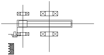
We draw a horizontal center line; on it with two vertical lines we show the center distance a w = 315 mm.
We draw a gear and a wheel in the form of rectangles; the gear is made in one piece with the shaft; the length of the wheel hub is equal to the width of the rim and does not protrude beyond the rectangle.
We outline the inner wall of the case:
a) the gap between the end of the gear and the inner wall of the housing A1 = 1.2 · δ = 1.2 · 8 = 9.6≈10 mm.
b) the gap from the circumference of the tops of the teeth of the wheel to the inner wall of the housing A = δ = 8 mm.
c) the distance between the diameter of the circumference of the tops of the gear teeth and the inner wall A = δ = 8 mm.
Preliminarily, we outline deep groove ball bearings of the middle series: for the drive shaft bearing 308: d = 40 mm, D = 90 mm, B = 23 mm, C = 41.0 kN, C 0 = 22.4 kN; for the driven shaft bearing 313: d = 65 mm, D = 140 mm, B = 33 mm, C = 93.3 kN, C 0 = 56.0 kN.
Bearing lubrication is a grease lubricant. To prevent the grease from washing out from the bearing, we introduce grease-retaining rings. Their width determines the size y = 12 mm.
Distance on the drive shaft l 1 = 72.7 mm, on the driven shaft l 2 = 77.7 mm. Let us finally accept l 1 = l 2 = 78 mm.
The depth of the bearing seat l g = 1.5 V; for bearing 308 B = 23 mm; l g = 1.5 23 = 48 mm.
The thickness of the flange Δ of the bearing cover is taken to be approximately equal to the hole d 0; in this flange Δ = 12 mm. The height of the bolt head is taken as 0.7 d b = 0.7 12 = 8.4 mm. We set the gap between the bolt head and the end of the pulley to 30 mm.
By measuring, we set the distance l 3 = 115.4 mm, which determines the position of the pulley relative to the nearest support, finally we take l 3 = 116 mm.