The history of the creation of automatic transmission
The idea of creating a transmission with an automatic transmission arose at the beginning of the last century. Some cars had gearboxes very similar to those used on modern cars.
In Europe, Mercedes produced in 1914 a small batch of cars with a gearbox, which can be conventionally called automatic.
In the late 1930s of the twentieth century, firms such as Chrysler, Ford and GMC came close to the development of mass production of cars with automatic transmission, and the first of these was GMC, which in 1940 began to install a transmission with automatic transmission.
Hydramatic for Oldsmobile and Cadillac vehicles. This transmission was composed of a three-speed gearbox with a hydraulic shift control system.
Further development of automatic transmissions, right up to the early 80s of the twentieth century, followed the path of improving production technology and improving the quality and reliability of the mechanical part of the automatic transmission. No fundamentally new solutions were used here.
At the same time, the automatic transmission hydraulic control system has been constantly modernized. They tried to bring it to complete perfection in order to provide the maximum comfort of a trip by car. As an example, we can cite the Mercedes company, which for its automatic transmissions 722.3, 722.4, 722.5 has developed an original and unique in complexity hydraulic circuit of the control unit.
Since the 1980s, car manufacturers have been using electronic control systems for automatic transmissions. This was first done in 1983 by Toyota. Then, in 1987, Ford also began using an electronic unit in A4LD transmissions to control the overdrive and torque converter lock-up clutch. Chrysler introduced the state-of-the-art A604 and A606 transmissions (41TE and 42LE) in 1984 for front wheel drive vehicles with a completely electronic and very progressive control system for that time. By 1991, GMC had developed the 4L60-E and 4T60-E transmissions, also with a fully electronic control system.
Today, there are two trends in the development of transmissions with automatic transmissions.
One of them is characterized by a constant increase in the number of gears. In the early 80s of the twentieth century, a fourth (overdrive) gear appeared in automatic transmissions, which was caused by the need to significantly improve the fuel and economic performance of cars. At the same time, a torque converter lock-up was used to achieve the same goal. Then in the early 90s of the same century with the aim of improving dynamic characteristics cars, five-speed automatic transmissions were developed (another reduction gear appeared). In early 2001, the German firm BMW began to install a six-speed automatic transmission from the ZF-6HP26 firm on its cars. Here, unlike the five-speed automatic transmissions, a second overdrive appeared. And finally, in recent years, firms such as Honda, Audi, Nissan and others have begun to actively use transmissions with a continuously variable gear ratio (CVT).
In accordance with the second trend in the development of transmissions with automatic transmissions, the electronic control unit and its software are being improved. At first, these were simple systems, the task of which was to determine the moments of gear changes and ensure the required quality of these changes. Then programs appeared that analyzed the driver's manner of driving and independently made a decision on the choice of the gear shifting algorithm (sporty or economical). In the future, a manual control function was added, which allowed the driver to independently determine the moments of gear shifting, as it happens in the presence of manual transmission... In addition, in parallel with the expansion of the automatic transmission control capabilities, the self-diagnosis program was improved.
Definition
Automatic box gear shifting(Automatic transmission, automatic transmission) - one of the types of gearboxes, the main difference from mechanical box gear shifting is that in the automatic transmission gear shifting is ensured automatically (i.e., the direct participation of the operator (driver) is not required). The choice of gear ratio corresponds to the current driving conditions, and also depends on many other factors. Also, if a mechanical drive is used in traditional gearboxes, then in an automatic gearbox there is a different principle of movement of the mechanical part, namely, a hydromechanical drive or a planetary mechanism is involved. There are designs in which a two-shaft or three-shaft gearbox works together with a torque converter. This combination was used on LiAZ-677 buses and in the products of ZF Friedrichshafen AG.
In recent years, automated manual transmissions with electronic control and electro-pneumatic or electromechanical actuators.
Background
No wonder they say that laziness is the engine of progress, so the desire for comfort and a simpler, more convenient life has given rise to many interesting things and inventions. In the automotive industry, such an invention can be considered an automatic gearbox.
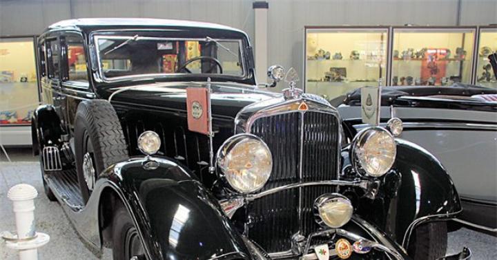
Although the design of the automatic transmission is quite complex and became popular only at the end of the 20th century, it was first installed in a Swedish Lisholm-Smith bus from 1928. In mass production, the automatic transmission came only 20 years later, namely, in 1947 in a Buick Roadmaster car. The basis of this transmission was the invention of the German professor Fettinger, who patented the first torque converter in 1903.

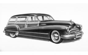
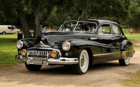
The photos show the same Buick Roadmaster - the first production car with automatic transmission.
In an automatic transmission, a torque converter acts as a clutch, which transfers torque to the gearbox from the engine. The torque converter itself consists of a centripetal turbine and a centrifugal pump, between which a guide vane (reactor) is located. All of them are located on the same axis and in the same housing, together with the hydraulic working fluid.
Closer to the present
The middle of the 60s of the 20th century was marked by the final consolidation and approval in the United States of the modern automatic transmission switching scheme - P-R-N-D-L... Where:
"P" (Parking) - "Parking"- The neutral mode is on, in which the output shaft of the box is mechanically blocked, so that the car does not move.
"R" (Reverse) - "Reverse"- Enabling the mode reverse(reverse gear).
"N" (Neutral) - "Neutral"- There is no connection between the gearbox output and input shafts. But at the same time, the output shaft is not blocked, and the car can move.
"D" (Drive) - "Main mode"- Automatic full circle switching.
"L" (Low) - Driving only in 1st gear. Only 1st gear is used. The hydrospreader is locked.
Increasing demands on the efficiency of cars led to the return in the 1980s of four-speed transmissions, in which the fourth gear had ratio less than one ("overdrive"). Also, torque converters that lock at high speed became widespread, which made it possible to increase the efficiency of the transmission by reducing the losses arising in the hydraulic element.
In the period from 1980-1990, the computerization of engine control systems took place. Similar control systems were used in automatic transmissions. Now control over the flow of hydraulic fluid was regulated by solenoids connected to the computer. As a result, gear shifting became smoother and more comfortable, and economy and work efficiency increased again. In the same years, it becomes possible to manually control the gearbox ("Tiptronic" or similar). The first five-speed gearbox gear. There is no need to change the oil in the gearbox, since the resource already poured into it is comparable to the resource of the gearbox.
Design
Traditionally, automatic gearboxes consist of planetary gearboxes, torque converters, friction and freewheel clutches, connecting drums and shafts. Sometimes a brake band is used, which slows down one of the drums relative to the automatic transmission housing when one of the gears is switched on.
The role of the torque converter consists in the transmission of moment with slippage when starting off. On high revs engine (3-4 gear), the torque converter is blocked by a friction clutch, which prevents it from slipping. Structurally, it is installed in the same way as the clutch on transmissions with manual transmissions - between the automatic transmission and the engine itself. The converter housing and drive turbine are attached to the engine flywheel, as is the clutch basket.
The torque converter itself consists of three turbines - a stator, input (part of the body) and output. Usually, the stator is deafly braked on the automatic transmission case, however, in some cases, the stator braking is activated by a friction clutch to maximize the use of the torque converter over the entire speed range.
Friction clutches("package") connecting and disconnecting the elements of the automatic transmission - the output and input shafts and the elements of planetary gearboxes, and braking them on the automatic transmission housing, the gear changes are carried out. The clutch consists of a drum and a hub. The drum has large rectangular grooves on the inside, and the hub has large rectangular teeth on the outside. The space between the drum and the hub is filled with annular friction discs, some of which are plastic with internal cutouts, where the teeth of the hub enter, and the other part is made of metal and has protrusions on the outside that enter the grooves of the drum.
The disc pack is hydraulically compressed by the annular piston, the friction clutch communicates. Oil is supplied to the cylinder through grooves in the shafts, the automatic transmission housing and the drum.

 Preview - click-to-enlarge.
On the first, on the left, the photo is a section of a torque converter eight-speed automatic transmission of a Lexus car, and on the second - a section of a six-speed preselective Volkswagen automatic transmission
The overrunning clutch slides freely in one direction and wedges with the transmission of torque in the other. Traditionally, it consists of an inner and outer ring and a cage with rollers located between them. Serves to reduce shocks in the friction clutches when shifting gears, as well as to disable engine braking in some automatic transmission modes.
A set of spools was used as a control device for the automatic transmission, which controlled the oil flow to the pistons of the friction clutches and brake bands. The position of the spools is set, both manually, mechanically by the selector knob, and automatically. Automation can be electronic or hydraulic.
The hydraulic automatic system uses the oil pressure from the centrifugal regulator, which is connected to the output shaft of the automatic transmission, as well as the oil pressure from the gas pedal pressed by the driver. As a result, the automation receives information about the speed of the car and the position of the gas pedal, depending on which the spools are switched.
The electronics use solenoids to move the spools. The cables from the solenoids are located outside the automatic transmission and lead to the control unit, which is sometimes combined with the fuel injection and ignition control unit. Depending on the position of the selector lever, accelerator pedal and vehicle speed, the electronics decides on the movement of the solenoids.
Sometimes, the automatic transmission is provided for without electronic automation, but only with the third forward gear, or with all forward gears, but with the obligatory shift of the selector handle. They will advise you on gearbox breakdowns and repairs.
In the USSR, the first hydraulic coupling was created in 1929 by A.P. Kudryavtsev, the first torque converter - in 1932-1934. at the Moscow Higher Technical School N.E.Bauman. The founder of domestic hydrodynamic transmissions is A.P. Kudryavtsev (he called them "hydraulic turbo transmissions"). A.P. Kudryavtsev dealt with all issues related to the design, testing and construction of hydraulic transmissions. He paid a lot of attention to the creation of methods for calculating torque converters and fluid couplings, published books:
- "Fundamentals of hydrodynamic transformation of mechanical energy", published by the UVMS of the Red Army, 1934;
- "Turbo transmissions for diesels", published by the Institute of Naval Shipbuilding (NIVK), 1937;
- "Turbo transmissions for ships", publication of Oborongiz of the USSR, 1939;
- "Design, construction and testing of hydraulic turbo transmissions", Mashgiz, 1947
BUREAU OF HYDRAULIC REDUCERS (Leningrad)
In the early 30s, the Bureau of Hydraulic Gearboxes was created in Leningrad, which developed hydrodynamic transmissions for various machines. In 1935, it developed for ZIL (then the ZIS Automobile Plant named after I.V. Stalin) two variants of an automobile hydraulic transmission (apparently, for a bus based on the ZIS-5 vehicle). In the first version (Fig. 1), a two-stage four-wheel hydraulic converter of the Lysholm-Smith type was used (pump, first stage of a turbine, reactor, second stage of a turbine). In the second version (Fig. 2), a three-stage six-wheel Lysholm-Smith torque converter was used (pump, first turbine stage, first reactor, second turbine stage, second reactor, third turbine stage).
The mechanical part of both variants contained one forward and reverse gear, i. E. it was supposed to accelerate only on a torque converter, followed by a switch to a mechanical direct transmission.
Through a two-disc clutch (see Fig. 2), the impeller of the gas turbine engine is driven. In the torque converter mode, the torque is transmitted from the turbine wheel to the input shaft of the mechanical part of the GMF and then through the toothed clutch (in Fig. 2 it is turned off) to the output shaft of the GMF. When the bus reaches a certain speed, the spline sleeve with face teeth, sitting on the input shaft of the mechanical part of the GMF, is shifted to the left. The sleeve meshes with the teeth on the impeller hub - a transition to a straight line is carried out mechanical transmission... In this case, the pumping and turbine wheels of the gas turbine engine begin to rotate with the engine speed. At the same time, the freewheel clutches on which the reactors sit are wedged, and the reactors begin to rotate freely together with the other wheels of the gas turbine engine, which avoids mixing losses working fluid... There is no information about the implementation of this project.
AUTO PLANT IM. I.A.LIKHACHEVA (ZIL) (until 1956 - ZIS)
An important role in acquainting the automotive technical community with automatic transmissions was played by the book by Professor of the Department of Hydraulic Machines VN Prokofiev MVTU named after NE Bauman VN Prokofiev "Automotive hydraulic transmissions" (Mashgiz, 1947). Realizing the prospects of such structures, one of the leaders of ZIL - the chief technologist of the plant F.S. Demianyuk - asked V.N. Prokofiev to send to ZIL at undergraduate practice two students of the Moscow Higher Technical School so that they would do their diploma projects on hydraulic transmissions for cars produced by the plant and stay at the plant.
In pursuance of this agreement, in the summer of 1948, MVTU students D.B. Breigin and Yu.I. Cherednichenko came to ZIL for their pre-graduation practice, who actually from that time began to work at the hydraulic transmission plant - first in the bus bureau of the Chief Designer department, and then in the Bureau of Hydraulic Units, created in March 1949, for the leadership of which E.M. Gonikberg, who previously worked in the technological department of the plant. Soon, S.F. Rumyantsev, V.I.Sokolovsky and E.Z.Bren were transferred to the bureau from other services of the plant, who together with Gonikberg, Cherednichenko and Breigin made up the backbone of the design bureau of hydraulic units in the first years.
Works on hydraulic transmissions at the plant were carried out for all types of cars produced by the plant - buses, cars, trucks and special vehicles.
ZIL - work on the bus GMP.
At the end of the Great Patriotic War and in the first post-war years in the USSR, the industry that worked for military needs was transferred to the production of peaceful products. Various options were worked out. Calculations showed, in particular, that if we take the cost of a car when it is produced at an automobile plant as 1, then the cost of this car will be 2.5 for production at an aircraft plant and 1.8 for production at an enterprise of the artillery department.
The production of buses after the war resumed at ZIL, which began to produce the ZIS-154 bus with the YaAZ-204 engine and power transmission ( car engine rotated the generator direct current, the generated current was used to rotate the wheels of the bus with a traction electric motor).
The ZIS-154 bus with a heavy and expensive electric transmission could not become a massive bus necessary for the country. Such a role could be performed only by a bus, in which the components and parts of a mass truck would be widely used. The ZIL-155 bus became such a bus. A hydromechanical transmission for it (Fig. 3) was designed in 1951.
Fig. 3. Hydromechanical transmission of the ZIL-155 bus
Attention should be paid to the fundamental difference in the power transmission scheme in the structures shown in Fig. 2 and Fig. 3. In the GMF, according to Fig. 2, there is one double-disc clutch and switching from the gas turbine engine to the direct transmission is carried out by a gear clutch. In the GMF, according to Fig. 3, there are two single-plate clutches and switching from a gas turbine engine to a direct transmission is carried out by switching from one clutch to another. The freewheel clutch, which prevents the rotation of the wheels of the gas turbine engine after switching to direct transmission, is located in the middle of the mechanical part of the GMF. This design is simpler and more reliable than the design with the location on the freewheel clutches of the gas turbine reactors.
In the process of developing the structure, a GMF with a gas turbine engine of two sizes was designed and tested - with the maximum working cavity diameters of 325 and 370 mm. As a result of road tests, the preference was given to the diameter of 370 mm.
During the tests, in addition to the direct transmission, an additional reduction gear was introduced into the mechanical part of the GMF. It was turned on manually only before passing through particularly difficult terrain.
After thorough tests of the first samples, a pilot batch of 6 ZIL-155 buses with GMF was built. These buses were tested in different cities on different routes, in different climatic zones. The runs reached 50 ... 70 thousand km. There was already every reason for recommending GMP for production, but unexpectedly at the level of the country's leadership, a decision was made, disastrous for the Soviet bus industry, that Hungary would make buses for all countries of the socialist camp. After this decision (1959?), The production of buses at ZIL was discontinued. Naturally, the work on the GMF for buses also stopped.
In recent years, before the removal of the production of buses from ZIL, projects of variants of buses with a rear transverse arrangement of the engine arose. This promised the buses great layout advantages (low floor height, etc.).
For this version of the bus, a special GMF was developed, built and tested (Fig. 4). Work on this GMP was also terminated due to the termination of the production of buses.

Fig. 4 GMP bus ZIL-129B
In the early 60s, ZIL created a 17-seater ZIL-118K bus with a ZIL-130 engine and a GMF of a ZIL passenger car adapted to work with this engine. The long-term practice of operating these buses has shown the full possibility of the operation of the GMF of a ZIL passenger car with an engine having significantly lower maximum revolutions (3200 rpm instead of 4600).
The release of several dozen ZIL-118K buses over many years cannot be considered a revival of bus production at ZIL. At present, however, we can talk about the expediency of continuing work on the bus theme by equipping the existing production of 16 ... 22-seat buses of the 3250 series with GMF modifications, which the plant began to produce. The diesel engine D-245.12 of these buses has a maximum speed of 2400 rpm.
The calculations of Yu.I. Cherednichenko show that in this case the GMF of the ZIL-4105 type is satisfactorily combined with the characteristics of the D-245.12 engine. In the GMF, the gear shift modes must be shifted and changes made to ensure operation without a vacuum corrector. The dynamics of the variant with the GMF will be practically the same as for the variant with the ZIL-130 manual transmission.
ZIL - work on GMF passenger cars
The first work on the GMF for ZIL cars began in 1949. Then the experimental GMF E111 for the ZIS-110 was designed. The transmission consisted of a single-stage five-wheeled gas turbine engine and a two-stage hydraulically controlled planetary gearbox. The main gear in the gearbox was direct, the downshift was intended only for particularly difficult driving conditions and was manually engaged (it could be engaged on the go).
The prototype for the GMP E111 was the GMP "Daynaflow" car.
Buick 70 Rodmaster, the production of which began in the USA in 1947. The Dynaflow hydraulic transmission served only as a literary prototype - there was no sample at the plant, information was taken from technical journals.
In 1950, a turbine transformer was manufactured and tested on a car (with cast wheels). Later, a Buick car with GMF was received and the drawings were corrected. However, work on this GMF was not developed due to the appearance of GMF with automatic switching gear.
In 1953-54. in connection with the forthcoming start of production of passenger cars ZIL-111, a GMP suitable for ZIL in the class of a 1953 Chrysler passenger car (model C-59 "Crown Imperial") was taken for the prototype of the GMP. GMP ZIL-111 was designed very close to the prototype (there was no exact borrowing), despite the tangible difference in the parameters of Chrysler and ZIL cars (primarily in terms of weight). The main functional units of the GMP ZIL-111: gas turbine engine, two-stage planetary gearbox, hydraulic control system (Fig. 5 and 6).
The configuration of the vane system, which determines the characteristics of the gas turbine engine, was taken exactly according to the Chrysler gas turbine engine, but the size of the gas turbine engine was changed (while completely preserving the type of the vane system), taking into account that the torque of the ZIL-111 engine was supposed to be about 15% higher than that of the Chrysler engine. (the maximum size of the working cavity was taken as 328 mm instead of 318 mm). The characteristics of the ZIL and Chrysler gas turbine engines turned out to be practically the same (the maximum transformation ratio K0 = 2.45 and the maximum efficiency in the torque converter mode is 0.88).
The GMP ZIL-111 was designed by D.B.Breigin, Yu.I. Cherednichenko and E.Z.Bren under the leadership of E.M. Gonikberg. Further work on the GMF of ZIL cars was carried out under the leadership of D.B. Breigin, since 19 .. Yu.I. Utkin actively joined this work, who then from 19 .. headed the design work until his departure from the plant at 19 ..
Fig. 5 GMP ZIL-111 (location of characteristic units)
Fig. 6 GMP ZIL-111 (power supply and control system)
Subsequently, the design of the gas turbine engine was simplified and improved. While maintaining the previous converting and load-kinematic characteristics, it was possible to use one reactor instead of two (while the pump and turbine wheels remained unchanged). The gas turbine engine, numbered 114-1709010, was made all-welded, which reduced its dimensions, weight and moment of inertia of parts associated with the engine (Fig. 7 and 8). Reducing the moment of inertia has a positive effect on the acceleration dynamics of the vehicle and on the improvement of the smoothness of gear changes.
Rice. 7 GDT ZIL-111

Fig. 8 GDT ZIL-114
When switching from a two-stage GMF to a three-stage one, accompanied by an increase in engine power, it was found expedient to have an option with a maximum transformation ratio reduced from 2.45 to 2.0. Such a gas turbine engine 114-1709010D was created by changing the configuration of the impeller and reactor blades. At the same time, its maximum efficiency increased by 1 ... 2%. It is now the standard equipment of the ZIL-41047 vehicle (in the longitudinal section, this gas turbine engine does not differ from the ZIL-114 gas turbine engine (Fig. 8).
The mechanical part of the GMP ZIL-111 had gear ratios of 1.72; 1.00; Z.H.-2.39. The GMF was controlled by a cable using the buttons on the control panel.
GMP ZIL-111 was the standard equipment of passenger cars ZIL-111 from the very beginning of their production in 1957. During the development tests and during the production of this GMF until the last days of its release in April 1975, many measures were taken to improve the reliability of the GMF. increased durability, improved quality of gear changes. A new oil for GMF was developed and introduced (oil A - still used).
At the same time, during operation, some drawbacks of the two-stage GMF were revealed, which could not be eliminated by improving the design of the GMF and the technology of its manufacture. These include:
- noise of gears in "neutral" caused by their rotation in this mode, which can be avoided with a different planetary mechanism;
- low efficiency of the GMF in a reduction gear due to the circulation of power in the planetary gear, which can also be avoided;
- the impossibility, with the gear ratio of the first gear 1.72, to realize the traction force that could be obtained based on the grip weight of the car;
- the inability to move in a lower gear with a gear ratio of 1.72 at a speed of more than 105 km / h, which makes it difficult to overtake Vehicle moving at a speed of 100-120 km / h.
The first two disadvantages can be eliminated by changing the scheme of the planetary mechanism. For the third, it is necessary to increase the gear ratio of the first gear. For the fourth - the presence of a gear, the gear ratio of which is closer to the gear ratio of the last gear (direct). Therefore, the plant settled on a three-stage GMF with gear ratios of 2.02; 1.42; 1.00; Z.H.-1.42. The planetary mechanism was made according to the original scheme, protected by the copyright certificate. As a result, GMP ZIL became patent-free.
The value of the reverse gear ratio was forced to be low - this is an inevitable feature of the adopted scheme of the planetary mechanism.
Work on this three-stage GMP ZIL-114D began in 1966. Several batches of experimental GMF were built, intensive tests were carried out, including road tests with runs up to 100 thousand km.
The production of the GMP ZIL-114D began in April 1975. The mechanical part of the GMP contained two planetary gears, three clutches, two band brakes, and a freewheel clutch.
During the transition of the plant from the ZIL-114 car to the ZIL-115 (4104) car, which has a more powerful engine and a slightly greater mass, the GMP 4104 was modernized. A number of changes have been made to it, including:
- a new design of the freewheel clutch with an increased number of rollers was applied (12 instead of 8);
- the control scheme of the planetary mechanism was changed, which made it possible to reduce the rotational speed of the clutch body parts and thereby increase the reliability of the GMF control system;
- the second clutch is strengthened by increasing the area of the pressure piston;
- a distributor valve was introduced into the hydraulic control system of the GMF, the piston strokes of the accumulators and the stiffness of their springs were changed, which generally improved the operation of the system.
Before the start of production of GMP 4104 (1978), these measures (and a number of others) were verified by tests, including long-term ones, of six experimental gearboxes.
The development of the GMP 4104 design was the GMP 4105 (Fig. 9), which was put into production in 1982. It does not have a rear pump, the drive of the locking mechanism is significantly simplified (while increasing reliability), and one additional possible range of motion of the car has been introduced.
Previously, to move forward, the driver could turn on the "D" position, in which the transition was carried out in gears 1-2-3, or turn on the "2" position, in which, depending on the vehicle speed and position throttle the engine was engaged in either 1st or 2nd gear. During the transition to the GMP 4105, the "1" range was added to the control system, in which it is possible to work only in the first gear - this creates certain conveniences when driving in especially difficult conditions and in mountainous terrain. At the same time, on the "2" range, an automatic transition 1-2 began.
During the modernization of GMP 4105, carried out in 1988, after which it received the number 4105-01, the design of the freewheel clutch and a number of adjacent parts was significantly changed, which increased the reliability of the GMF.
In the following (nineties) years, a number of design developments were carried out, some of which were verified by tests. They are waiting for the intensification of work on the GMF of ZIL cars.

Rice. 9 (Figure 3.5 TO 156-95)
ZIL - work on GMF trucks
ZIL did not produce trucks general purpose with GMP, however, experimental work in this direction was carried out. First of all, it is necessary to note the GMP ZIL-153 for the car off-road, made according to the WSK scheme (gas turbine engine - clutch - manual gearbox). Formally, such a design (Fig. 10 - designers V.I.Sokolovsky and P.S.Fomin) cannot be considered, as already noted, an automatic transmission due to the lack of automatic gear changes, but is a step towards them. In the design of Fig. 10, the blocking unit of the gas turbine engine deserves attention, which allows, in certain modes, to rigidly connect the turbine wheel of the gas turbine engine to the impeller and thereby ensure the operation of the GMF in the mode of a manual transmission.
Rice. 10. GMP ZIL-153
During tests, an all-terrain vehicle with GMP ZIL-153 produced good impression, but it was found expedient to further focus on transmissions with automatic gear shifting. Such GMFs were designed, built and tested. Structures with a parallel arrangement of shafts in the mechanical part (GMP ZIL-7E131 and ZIL-7E131A) and designs with a mechanical part of the planetary type were tested. Fig. 11 shows a three-stage shaft GMP ZIL-7E131A (designers V.I.Sokolovsky and P.S.Fomin), Fig. 12 shows a four-stage planetary GMP ZIL-8E131 (designer D. Breigin).


These works did not receive further distribution.
ZIL over the years periodically had contacts with Allison (USA), a large and long-standing manufacturer of GMF for civil and military vehicles. For about 12 years, comparative tests of two ZIL-130 V1 tractors were carried out - one with a GMP, the other with a standard mechanical transmission... The positive effect of GMF on the durability of vehicle units has been revealed. The results are given in the previous information N 1 "Advantages of vehicles with hydromechanical transmissions". The Allison firm considered the tests carried out to be unique and asked ZIL to transfer to it the GMF, which had passed 870 thousand km during tests, for the firm's museum.
ZIL - work on GMF for special trucks
In the 60s, ZIL, together with the Bryansk Automobile Plant, produced ZIL-135 vehicles equipped with a GMP design and production by ZIL. These vehicles were used as a landing gear for rocket technology and as search and recovery devices for spacecraft. For many years they were in service with the Soviet Army.
The introduction of a new for that time transmission on a car of such a critical purpose became possible thanks to the technical courage of the Chief Designer of SKB ZIL V.A. Grachev. GMP ZIL-135 - six-speed (designers V.I.Sokolovsky and S.F. Rumyantsev). Structurally, it is made in the form of a three-stage automatic transmission and a two-stage demultiplier combined with it (Fig. 13). The gas turbine engine in the GMP is made on the basis of the gas turbine engine ZIL-111 with the maximum transformation ratio increased to 2.7 (designer A.N. Narbut).
Gear ratios of the gearbox: 2.55; 1.47; 1.00; Z.Kh. -2.26. Transmission ratios of the demultiplier: 2.73; 1.00. Cherednichenko Kharitonov Leonov Lavrentyev Sobolev Anokhin The control scheme of the GMP ZIL-135 is shown in Fig. 14. Over the years of production of the ZIL-135 car, about 300 GMPs were produced.

ZIL - a system for testing and fine-tuning automotive GMF to the required functional and reliability indicators
There was no experience of work on automobile GMF in 1949 at ZIL (and in the country). The creation of the design bureau and the release of technical documentation for the GMF was only the beginning of the work. It was required to create a system for testing and fine-tuning the GMF to the required functional and reliability indicators. Required to define structure and logical organization necessary work, to develop methods of testing and refinement, to create test equipment, to provide information for technological studies.
Such a system was developed simultaneously with the organization of the production of GMF and was improved during production. Description of the GMF testing and debugging system is in separate information.
GORKOVSKY AUTO PLANT (GAS)
Start of work on hydraulic transmissions at GAZ it was laid by the equipment of the mechanical gearbox of the ZIM car with a hydraulic clutch. Such a kit can in no way be considered an automatic transmission, but it served as a clear example of the advantages brought by the introduction of a hydraulic element into the transmission, and served as an impetus for work on automatic transmissions- hydromechanical transmissions. GAZ-13 "Chaika" cars were equipped with such gears. They were also used on some modifications of Volga cars.
For the prototype of the GMF (designer BN Popov), the three-stage GMF was taken, which was used on the cars of the Ford corporation.
The active diameter of the gas turbine engine (Fig. 15) is 340 mm, the maximum transformation ratio is K0 = 2.4.
Rice. 15 Hydraulic torque converter GMP car "Chaika"
Gear ratios of the planetary gearbox: first gear - 2.84; the second - 1.68; third - 1.00; reverse gear - 1.75. Longitudinal and transverse sections of the mechanical part of the GMF are shown in Fig. 16. The production of "Chaika" cars began in 19 .. and was discontinued in 19 ..
Rice. 16 a) Longitudinal section of GMF car "Chaika"
Rice. 16 b) Cross section of the GMF of the car "Chaika"
LVIV BUS PLANT - US (LAZ - US)
Since 1963 Lviv bus factory(LAZ) began to produce the hydromechanical transmission LAZ-NAMI-035, designed by this plant together with US. This GMF was designed to work with carburetor engine with a capacity of 150-200 h.p. and a torque of 40-50 kgm. Tens of thousands of LiAZ-677 buses were produced from this GMP.
In the GMF (diagram in Fig. 17), a gas turbine engine, successfully designed by NAMI (S.M. Trusov), was used, which served as a prototype for many gas turbine engines in other GMF. In GMP LAZ-NAMI-035, a gas turbine engine with a maximum transformation ratio K0 = 3.2 was used.
GMP LAZ-NAMI-035 - two-stage. The first gear ratio is 1.79; second gear - 1.00; reverse - 1.71. The gas turbine engine can be blocked. The design of the GMF is shown in Fig. 18.
The design of the GMF LAZ-NAMI-035 served as the basis for a number of modifications of the GMF, including for buses with diesel engines.
There is also a variant of a three-stage GMF.

Rice. 17 Diagram of hydromechanical transmission LAZ-NAMI-035
![]()
For the first time in the practice of domestic autobuilding, a domestic design served as a prototype for a foreign GMP.
NAMI, together with the research institute of automobiles UVMV (Czechoslovakia) and the plant "Praga" (Czechoslovakia), have developed a hydromechanical transmission NAMI-"Prague" 2M-70 for large-capacity city buses equipped with diesel engine with a capacity of 180-200 h.p. at 2100 rpm with a torque of 70-80 kgm.
This GMP (Fig. 19 and 20) has been produced by the Praga plant since 1967.

Rice. 19 Diagram of hydromechanical transmission NAMI- "Prague" 2M-70
BELARUSIAN AUTOMOBILE FACTORIES
In Belarus, cars with GMP are produced by the Minsk Automobile Plant (MAZ), the Belarusian Automobile Plant (BelAZ) and the Mogilev Automobile Plant (MoAZ). The first two factories are best known. GMP MAZ-530 for a dump truck of extra heavy carrying capacity (up to 45 tons) is designed to work with a 450 hp engine. with a maximum torque of 200 kgm. The GMF has a step-up gearbox that allows you to shift the engine characteristic in terms of revolutions for better alignment with the characteristics of the gas turbine engine. The active diameter of the circulation circle of the gas turbine engine is 466 mm, the maximum transformation ratio is K0 = 4. GMP MAZ-530 (Fig. 21) has three forward gears (3.36; 1.83; 1.00) and two reverse gears (2.60 and 1.40).

GMP BelAZ-540 (Fig. 22) is also designed for heavy-duty dump trucks. It has an accelerating gearbox, a gas turbine engine with an active circulation circle diameter of 466 mm and a maximum transformation ratio of K0 = 3.6 and a gearbox with three forward gears (gear ratios 2.6; 1.43; 0.7) and one reverse gear (gear number 1.6).

KAZAN MOTOR-BUILDING PRODUCTION ASSOCIATION (JSC KMPO)
Recently, an attempt has been made to organize the production of GMF for city buses at KMPO JSC under a license from VOITH.
The DIWA system mastered by this company was taken as a basis. A feature of this system is the branching of the power flow into two parts - one goes through the mechanical part of the transmission, the other through the hydraulic one.
Starting off is carried out only through the hydraulic part, and as the speed increases, the hydraulic share constantly decreases and the share of the mechanical part increases.
This is done by positioning the gas turbine engine between two planetary gearboxes (Fig. 23). In the first gearbox, the power flow is divided, in the second, it is combined.
There are three- and four-stage GMF options for 185-245 kW engines with 90-130 kgm torque.
Ever since the beginning of the twentieth century, attempts have already been made to create a box with automatic gear shifting. But only a few had a mechanism that vaguely resembled a modern automatic transmission device on a car. The pioneer in this business was the then not very popular German company "Mercedes", having released in 1914 several cars with a transmission box, which at a stretch could be called automatic.
The pioneer in the production of cars with automatic transmission is the German company "Mercedes"
Two decades later, the Chrysler, Ford and JMS firms have completely launched mass production of cars with automatic transmissions. The first of these three was "JMS", which in the early forties of the twentieth century began to install automatic transmission boxes.
The system was named "Hydramatic" and was first installed on Cadillac and Oldsmobile cars. This type of transmission consisted of three speeds, and all this was controlled using hydraulic system gear control.
Improvement in hydraulics and electronics
No fundamentally revolutionary breakthroughs in this area took place until the early eighties of the twentieth century. All new technological solutions were aimed exclusively at enhancing the strength and wear-resistant characteristics of the mechanical component of an automatic transmission.
The hydraulic component was also constantly pursued by upgrades and changes. All attempts of manufacturing companies were aimed at making the trip by car with automatic transmission as long, comfortable and fast as possible.

Improvement of hydraulics and electronics of automatic transmission belongs to Mercedes
The innovator in this area was the same "Mercedes", using one of the first for its manufactured cars, the latest system, which had no analogues at that time, ensuring high-quality operation of the control unit of the entire hydraulic system.
After the eighties of the twentieth century, fully electronic control systems came into use. Most of these developments were carried out by Japanese car companies. The first among them to do this was the company "Toyota" in 1983. Four years later, Ford repeated the success of its competitor by introducing a lock-up and overdrive unit in the torque converter clutch. electronic circuits management.
Shortly before that, in 1984, Chrysler introduced to the world the latest technology Exclusively for front-wheel drive vehicles, where all gearshifts were electronically controlled. For the whole world then this technical solution became a real sensational "boom" in the world of automobile electronic systems management.

In 1984, Chrysler released front-wheel drive vehicles, where all gearboxes were electronically controlled.
A little late, in the early nineties already "JMS" created fully electronically controlled car control circuits.
Development of modern automatic transmission technologies
Looking at how modern automatic transmission technology is moving, one area is to continually try to maximize the number of shifted gears in a transmission. Not many people know, but the fourth increasing "speed", which is now taken for granted, appeared only in the early eighties of the twentieth century. First of all, this was done in order to significantly reduce the fuel consumption of the car when driving in high-speed overdrive gears and achieve higher speed characteristics... For this, a device was created that is responsible for the torque converter lock. And already in the early nineties, the fifth accelerating speed and one additional decreasing speed were added to the car's transmission.
The six-speed automatic transmission was first installed on a car in 2001 by the German company BMW. Unlike all automatic transmissions existing at that time, a second gear up was added to the transmission.

Continuously variable transmissions are increasingly being introduced by Honda and Nissan
In modern automotive technology, innovators are Japanese companies Honda and Nissan, more and more introducing continuously variable transmissions.
The second direction is the development of the electronic component and the development of better software. At the beginning, the scheme was elementary, the meaning of which was only in tracking the exact moments of switching. After that, software appeared, which itself made the necessary decision for the driver, based on his previous decisions. Next, a manual transmission control system was developed, where the driver himself chose the required shift point. At the same time, the self-diagnostic programs used in the automatic transmission were being modernized.