ATVs can be equipped with two types of engines: electric and gasoline. Electric motors have less power and low energy reserves. If you take the average ATV with an electric motor, the range is about an hour, and then you need to recharge the batteries for a long time. In this regard, children's ATVs are equipped with this type of motor.
The most common ATV engines
Gasoline engines are most widely used in ATVs. They deliver high power, which, when paired with the transmission, is converted into high torque. Thanks to this, ATVs feel so great on any off-road. Also, an important indicator is the specific power (power per unit mass). The low weight of the motorbike coupled with a good engine allows the four-wheelers to show amazing cross-country ability. For ATVs, motors with a working volume of about 49 - 900 cubes are used. Of course, there are smaller volumes that are intended for children's versions of devices.
The difference between gasoline engines for ATVs

ATV gasoline engines can be divided into two large groups: two-stroke and four-stroke. The difference between these two types is that in a two-stroke engine, the piston completes one working cycle in one movement. In a four-stroke engine, injection, compression, detonation and exhaust are all performed in two piston strokes. Based on this, we can say that a two-stroke engine produces more power for the same cylinder volume. For example, one of the most common ATVs Stels ATV 300 is equipped with a four-stroke engine. two-stroke engine it is necessary to fill in oil. However, this is not a completely correct judgment, since there are many engines that do not require this, for example, Catarpillar engines do not require oil in gasoline. Of course, talk that two-stroke engines produce more harmful substances is true, but it should be understood that this is due to a higher frequency of fuel combustion in the cylinder. It can be noted that mechanical engineering technologies are today so developed that the emissions of different types of motors differ little and are minimized.
ATV engine maintenance

The performance of the power unit depends directly on the quality of service and frequency. Service maintenance of two-stroke engines is carried out much more often compared to four-stroke ones. This is primarily due to the fact that more frequent combustion of the air-fuel mixture occurs in the cylinder. As a result, a higher engine operating temperature is achieved. Such factors lead to faster wear of parts of the power unit operating in a two-stroke cycle.

Therefore, when purchasing an ATV with a two-stroke engine, be prepared for more frequent service and purchase of spare parts. The indisputable advantage of a two-stroke engine is its low weight and simplicity. But at the same time, there are many disadvantages: high consumption oil and fuel, high vibration and noise. For example, the Omaks Dragon ATV-024-15 ATV is equipped with a two-stroke engine.
However, athletes and ATV enthusiasts pay little attention to the collection of the engine; the most, perhaps, the most important point in the choice is the power output. In terms of power, it can be noted that a two-stroke engine is superior to a four-stroke engine with the same volume.
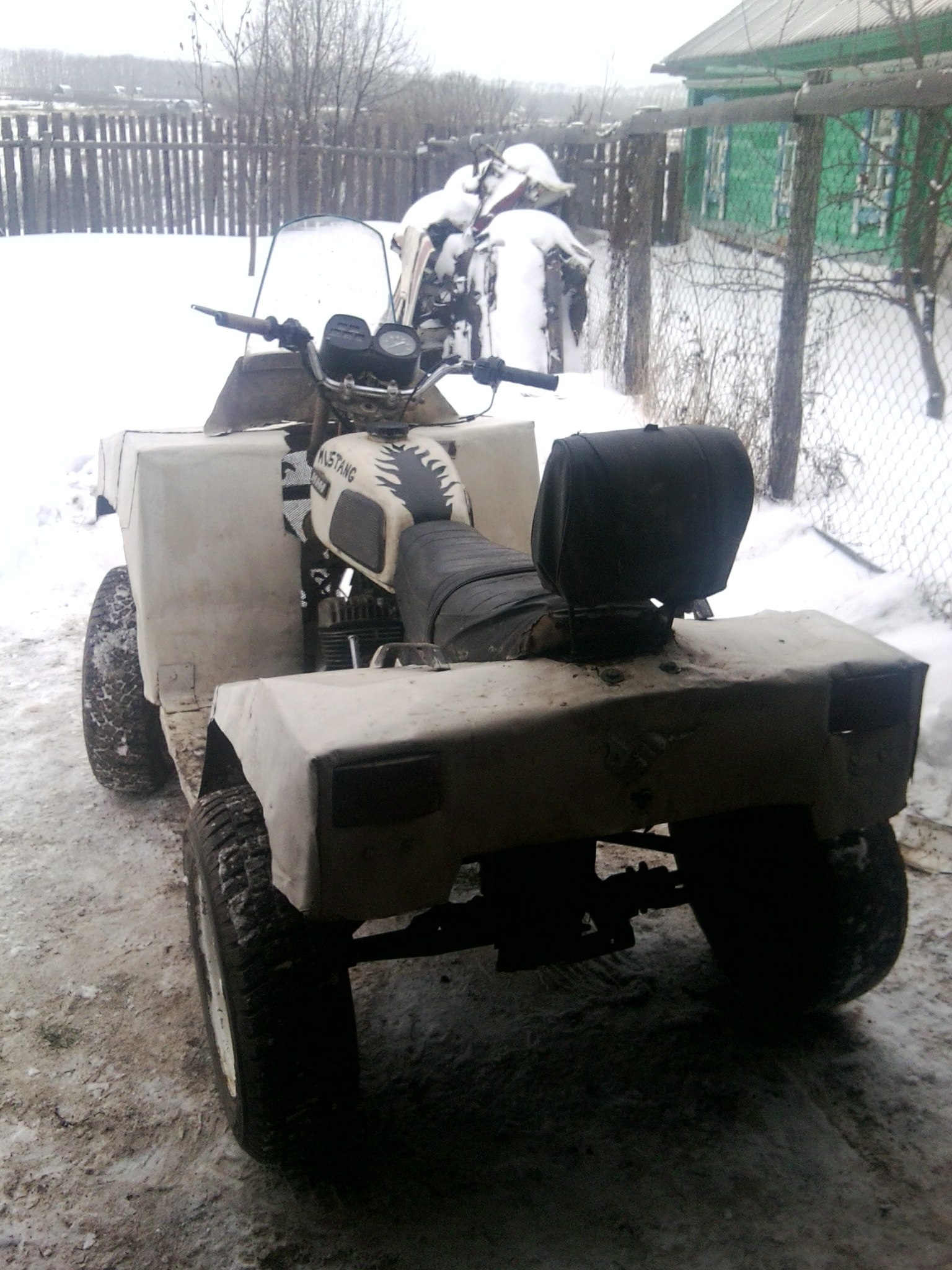
We present the ATV of our permanent author S. Pletnev from the city of Ocher, Perm Territory. The next car he built testifies to the increased design level and professional skills of its creator. However, judge for yourself ...
A year has passed since the time when I drove out of the garage and tested my first ATV with rear drive wheels based on the Ural-2 heavy motorcycle. And then the thought came: why not now make an all-wheel drive ATV(from the English. All Terrain Vehicle- all-terrain vehicle; such an international designation was given to similar machines).
A year of labor for 3-4 hours after work and on weekends - and new car was ready for testing, there were only small (and I would say pleasant) improvements: connection lighting equipment, installation of an ignition lock, rear-view mirrors and other little things.
Power unit for my ATV there was an engine from the car "Oka" - 32-horsepower, two-cylinder, four-stroke, liquid cooling. And if for a car its power was often not enough, then for an ATV it should have been more than enough.

ATV basic data:
Weight, kg ............................................... .......... 430
Length, mm ............................................... ........ 2300
Width, mm (along the outer sidewalls of tires) ......... 1250
Height, mm:
on the steering wheel ................................................ .......... 1250
on the saddle ................................................ .......... 900
Ground clearance, mm ...................................... 300
Base, mm ............................................... .......... 1430
Track, mm ............................................... ........ 1045
Maximum speed, km / h .............................. 65

Machine frame- spatial, welded. Its main elements (two pairs of spars: upper and lower) are made of round pipes of the VGP-25 type (water and gas pipes with a diameter of 25 mm and a wall thickness of 3.2 mm), auxiliary (struts, crossbars, etc.) are made of VGT-20. The side members are bent: the lower ones are in the horizontal plane, the upper ones are in the vertical plane. He bent pipes on a pipe bender, "cold". I welded the lugs (pairs of lugs) for fastening the levers and shock absorbers to the frame at once, and welded various brackets as the assemblies and assemblies were mounted (in place).

ATV transmission- kind. Although the car is all-wheel drive, but transfer case it is not. As you know, in "Oka" the engine is located across, and on the ATV it is installed along. This made it possible to direct the output shafts from the gearbox (gearbox) not to the right and left wheel (as in a car), but to the front and rear axles. That's just myself power unit, interlocked with the "basket" of the clutch and gearbox, had to be shifted slightly to the left relative to the longitudinal plane of symmetry in order to reduce the horizontal angle of the longitudinal drive transmission pivot shafts. Well, their vertical angles turned out to be insignificant.
The transmission is composed of units of various domestic cars, mainly "VAZ" models. But the finished industrial units also had to be refined. For example, from the checkpoint (from "Oka") to ensure the optimal (reduced) speed and increase the torque, he removed the main gear pair and replaced it with a chain transmission. The gearshift rod was also made different - lengthened, with outlets on both sides of the gearbox. The stem can be fixed in three positions: to engage 1st and 2nd gears, 3rd and 4th and reverse. The lever for selecting these positions is on the right side, and the gearshift lever is on the left.

Interwheel reducers- from rear axles VAZ "classics", only their axle shafts together with the "stockings" were removed and replaced with shafts with constant velocity joints from front-wheel drive models. CV joints are used as hinges in the rest of the transmission intermediate shafts.
There are no low gears and no differential locks.
Steering- motorcycle type (lever and shaft) at the top and automobile type(with steering rods) - at the bottom, only simplified, without a steering mechanism, with one bipod. At first I used the steering wheel from a motorcycle "Minsk", with a pipe diameter of 22 mm, but it turned out to be a little thin. Later I found and delivered it from a Ural motorcycle. The steering shaft is made of a tube with a diameter of 20 mm and a wall thickness of 2.8 mm. It has a travel stop at its lower end. At the bottom, the shaft rests on a thrust bearing, and in the middle part it turns in a split nylon bracket-sleeve.
Bipod made of steel sheet 8 mm thick, shaped like the letter "T". A hole with a diameter of 20 mm is made at the edge of the "rack" - the steering shaft is inserted and welded into it, and in the ears there are tapered holes for the ball ends of the steering rods. These holes are reinforced with matching welded washers. The bipod ears are slightly bent down so that they are almost parallel to the rods.
Wheels- 15-inch, from the car "Chevrolet-Niva". Tires with the corresponding rim dimensions 205/70 (width / height as a percentage of the width) with an off-road tread pattern. The wheel roll-in diameter is about 660 mm.
Wheel suspension- independent, on two triangular wishbones each (upper and lower) with shock absorbers from the Oka car (front). Levers are welded from round pipes of the VGP-20 type. Elastic elements (springs) and shock absorbers - from the car "Oka" (rear). Wheel hubs are welded into the wheel ends of the front levers and steering knuckles- from a VAZ-2109 car. Both those and others had to be finalized. In the hubs I installed studs under the wheels from the "Niva", and in the front fists - homemade swivel levers.
Muffler- homemade, two-piece. To protect it from thermal warping, the body kit covered it with a remote cover, and insulated the inlet pipe with asbestos.
ATV body kit- fiberglass. I pasted it for the first time, and therefore first studied the recommendations for performing the relevant work. But as it turned out, this process is painstaking, although the result is worth it.
First, I made the required contours of the body kit from a steel square pipe with a section of 10x10x1 mm. Fortunately, this pipe bends easily even with hands over the knee. The contour was welded to the frame with the help of jumpers from the same pipe, in places where later (after gluing the body kit), it would be easy to cut the "tacks". Then he bent the "wings" from hardboard (fiberboard) and fixed them with self-tapping screws to the contour and lintels. Where the bend turned out to be steep, I fastened separate strips of the same hardboard. The front end was taken out with styrofoam purchased from a hardware store. It was possible to use polystyrene or the same polyurethane foam, but the expanded polystyrene turned out to be more suitable material- well cut with a sharp thin knife. I glued individual elements from it into a general structure on polyurethane foam.
False tank- complex shape. It was not possible to bend it out of hardboard. Therefore, having wrapped the engine with plastic wrap, I began to fill the space intended for it with layers of polyurethane foam. After each layer, drying is mandatory, otherwise a thick foam volume may not dry out inside. I filled it until the layers went beyond the outline. Finally, after the foam was completely dry, I began to draw the desired shape with a knife. The edges were smoothed out with coarse sandpaper.
Under instrument cluster part went into action dashboard Oki. I also fixed it on the disc with the help of polyurethane foam.

Since the foam is coarse, the pores were filled with gypsum and then processed. When the shape of the blank began to respond to the conceived design and its surface became more or less smooth, I covered the blank with PF-115 paint. Since I was not going to make a matrix for gluing the body kit on the dummy, but immediately glued the body kit on it, followed by finishing the surface to ideal condition, then plastering and painting the boob could be neglected.
So, the idiot is ready and in order to glue a high-quality product, it took: 10 kg of epoxy resin, 1 kg of plasticizer for it and 1 kg of hardener, 15 running meters of non-thick fiberglass, 5 m of glass mat, brushes, gloves. Wearing breathing protection is highly desirable. And the more expensive they are, the more reliable. But experience, as is known, cannot be bought, so I gained it in the process.
I used transparent tape as a separating layer between the dummy and the product. Carefully, without gaps, the whole blockhead pasted over it with stripes. It took only 1.5 rolls of wide tape.
Diluted resin in 200-300 grams with a hardener and plasticizer. I used measuring cups and syringes, which is not very convenient. Before that, I cut strips of fiberglass in such sizes that large canvases lay on flat surfaces, and on irregularities, pieces of fabric could repeat them without making folds. By the way, fiberglass stretches moderately along the diagonal of the weave, "flowing" around the desired shape.
First, I smeared thickly with epoxy resin one area of the boob, put glass cloth on it and soaked it on top again with resin. The adjacent piece of fabric was glued using the same technology with an overlap of 3-5 cm. We had to work quickly - the resin sets pretty quickly, and the higher its temperature, the faster. Yes, I also warmed up the resin a little near a powerful illumination lamp for better fluidity.
After obkpeyki boob with fiberglass in one layer, he began to paste over it with glass mat. I got the glass mat quite thick, and it turned out to be good for them to gain the thickness of the product. But it does not fit irregularities, so I used it only on flat (or with a slight deflection) surfaces and without overlap. Resin impregnation was carried out in the same way as when working with fiberglass. It should only be taken into account that a lot of resin is used to impregnate a stekomat, so you need to dilute it more. Uneven surfaces after gluing the stekpomat were glued in several layers with a cloth. Each subsequent layer was applied after the previous one had a little set, so that the resin would not leak. And since the process of gluing the body kit took more than one day, after a day's break, it was necessary to "rough" the surface with coarse sandpaper and degrease - after all, the resin hardens completely during this time. The final layers on top of the mat were again covered with fiberglass, and not even one layer.
Since I needed a surface, as they say, the smoother, the better, and the experience was not enough, the dips and pits still remained - I poured them somewhere with one resin, and sometimes with the imposition of pieces of fiberglass. There was not enough resin. I bought it already in the household store, in boxes. I liked working with her more, because it was already packaged, and all that remained was to mix the components. And it dried faster than the one purchased at the company.

After the glued body kit had completely dried, I made cuts in it, dividing the product into three parts: rear fenders and rear, false tank with under-seat, front fenders and front end. Carefully, slightly prying and pulling with his hands with poking around, he separated the product in parts without much effort from the dummy.
Now, having removed the parts, I began to process them separately, bringing them to the desired result. In general, the usual preparatory and painting work on "all" technology: first, rough grinding with the removal of large bulges of resin and fiberglass; then painstaking filling of recesses with fiberglass putty; then sanding the outer surface and a primer with a plasticizer. In conclusion - painting with "metallic" and coating with varnish with a plasticizer.
The blockhead also carefully cut and put it in the far corner - just in case. The body kit was attached to specially made and welded "in place" mounts on the frame.
Roof racks. In conclusion, I welded the front and rear trunks from thin-walled steel pipes with an outer diameter of 20 mm, and in addition to them - "kenguryatniks" replacing the bumpers.

Four-wheel drive ATV drawings

ATV ATV:
1 — front wheel(from the Chevrolet-Niva car, 2 pcs.); 2 - engine (from the car "Oka"); 3 - front wheel drive transmission; 4 - a gearbox (from the Oka car); 5 - rear wheel drive transmission; 6 - frame; 7 - rear wheel (from the Chevrolet-Niva car, 2 pcs.); eight - fuel tank(20 liter canister); 9 - rear trunk; 10 - muffler; 11 - backrest of the passenger (headrest from the car "Oka"); 12 - saddle; 13 - clutch basket (from the Oka car); 14 - gear fixing lever; 15 - body kit (fiberglass); 16 - steering wheel (from the Ural motorcycle); 17 - instrument panel (from the Oka car); 18 - front trunk.

Kinematic diagram of the ATV-ATV transmission:
1 - motor (from the car "Oka"); 2 - clutch (from the Oka car); 3 - gearbox; 4 - CV JOINT (from the VAZ-2108 car, 12 pcs); 5 - main gear reducer with differential (from VAZ-2105, 2 pcs.); 6 - shaft (from the car VAZ-2108, 6 pcs.); 7 - wheel (from the Chevrolet-Niva car).

Quad frame:
1 - lower spar (pipe d25x3.2, 2 pcs.); 2 - upper spar (pipe d25x3.2, 2 pcs.); 3 - stand (pipe d25x3.2, 2 pcs.); 4 - support for the rear upper suspension arm (pipe d25x3.2, 2 pcs.); 5 - rear strut (pipe d20x2.8, 2 pcs.); 6 - support of the front upper suspension arm (pipe d25x3.2, 2 pcs.); 7 - front strut (pipe d20x2.8, 2 pcs.); 8 - the upper support of the front shock absorber (corner 35x35); 9 - rack of the upper support of the front shock absorber (sheet s5, 2 pcs.); 10 - front engine mounting support (sheet s3, 2 pcs.); 11 - rear engine mounting support (sheet s3, 2 pcs.); 12 - lugs for fastening levers and shock absorbers of suspensions (sheet s5, 18 pairs); 13 - saddle mounting bracket (sheet s3, 2 pcs.); 14 - upper transverse link (pipe d20x2.8); 15 - lower transverse link (pipe d20x2.8, 2 pcs.); 16 - radiator support (pipe d25x3.2 cut in half lengthwise, 2 pcs.); 17 - front console of footrests (pipe d20x2); 18 - rear console of footrests (pipe d20x2); 19 - connection of the front and rear footrest consoles (pipe d20x2); 20 - footboard cross member (sheet s5, 4 pcs.); 21 - an eyelet for attaching a fiberglass body kit (sheet s5, set).

Wheel suspension arms (a- the upper arm of the front suspension; b- the lower arm of the front suspension; v- lower arm rear suspension; G- the upper arm of the rear suspension; all parts, except those noted specially, are made of VGT-20 pipe):
1 - beam (2 pcs.); 2 - cross member; 3 - bushing (pipe d37x32, 2 pcs.); 4 - shock absorber mounting eye (steel, sheet s3); 5 - ball joint (from the steering rod of the Zhiguli car).

Steering column assembly:
1 - steering shaft (pipe d20x2.8); 2 - rudder connection plate (steel, sheet s6); 3 - brace of the plate (steel, sheet s6, 2 pcs.); 4 - split bracket-sleeve of the steering shaft (nylon, sheet s18); 5 - support washer (steel, sheet s6, 2 pcs.); 6 - bipod (steel, sheet 18); 7 - rudder travel stop (steel, sheet s6); 8 - bearing housing; 9 - a persistent tip (steel, circle 15); 10 - thrust bearing.

Trunks:
a- front; b- back.
"Encyclopedia of Technologies and Techniques" Patlakh V.V. 1993-2007
 We present the ATV of our permanent author S. Pletnev from the city of Ocher, Perm Territory. The next car he built testifies to the increased design level and professional skills of its creator. However, judge for yourself ...
A year has passed since I drove out of the garage and tried out my first ATV with rear wheel drive (). And then the thought came: why not make now an all-wheel drive ATV (from the English All Terrain Vehicle - an all-terrain vehicle; such an international designation was given to such machines).
Fortunately, at this time a buyer turned up on a buggy (), and the proceeds went towards the implementation of a new project.
 A year of labor for 3-4 hours after work and on weekends - and the new car was ready for testing, there were only small (and I would say pleasant) improvements: connecting lighting equipment, installing an ignition switch, rear-view mirrors and other little things.
The power unit for my ATV was the engine from the Oka car - 32-horsepower, two-cylinder, four-stroke, liquid-cooled. And if for a car its power was often not enough, then for an ATV it should have been more than enough.
The frame of the machine is spatial, welded. Its main elements (two pairs of spars: upper and lower) are made of round pipes of the VGP-25 type (water and gas pipes with a diameter of 25 mm and a wall thickness of 3.2 mm), auxiliary (struts, crossbars, etc.) are made of VGT-20. The side members are bent: the lower ones are in the horizontal plane, the upper ones are in the vertical plane. He bent pipes on a pipe bender, "cold". I welded the lugs (pairs of lugs) for fastening the levers and shock absorbers to the frame at once, and welded various brackets as the assemblies and assemblies were mounted (in place).

1 - front wheel (from the Chevrolet-Niva car, 2 pcs.);
2 - engine (from the car "Oka");
3 - front wheel drive transmission;
4 - a gearbox (from the Oka car);
5 - rear wheel drive transmission;
7 - rear wheel (from the Chevrolet-Niva car, 2 pcs.);
8 - fuel tank (20 liter canister);
9 - rear trunk;
10 - muffler;
11 - backrest of the passenger (headrest from the car "Oka");
12 - saddle;
13 - clutch basket (from the Oka car);
14 - gear fixing lever;
15 - body kit (fiberglass);
16 - steering wheel (from the Ural motorcycle);
17 - instrument panel (from the car "Oka");
18 - front trunk
The transmission of the all-terrain vehicle is peculiar. Although the car is all-wheel drive, there is no transfer case in it. As you know, in "Oka" the engine is located across, and on the ATV it is installed along. This made it possible to direct the output shafts from the gearbox (gearbox) not to the right and left wheel (as in a car), but to the front and rear axles. Here are just the power unit itself, interlocked with the "basket" of the clutch and gearbox, had to be shifted relative to the longitudinal plane of symmetry a little to the left in order to reduce the horizontal angle of the longitudinal hinge shafts of the transmission. Well, their vertical angles turned out to be insignificant.
 The transmission has been assembled from units of various domestic cars, mainly "VAZ" models. But the finished industrial units also had to be refined. For example, from the checkpoint (from "Oka") to ensure the optimal (reduced) speed and increase the torque, he removed the main gear pair and replaced it with a chain transmission. The gearshift rod was also made different - lengthened, with outlets on both sides of the gearbox. The stem can be fixed in three positions: to engage 1st and 2nd gears, 3rd and 4th and reverse. The lever for selecting these positions is on the right side, and the gearshift lever is on the left.
Interwheel reduction gears are from the rear axles of the VAZ "classics", only their axle shafts together with the "stockings" were removed and replaced with shafts with CV joints from front-wheel drive models. CV joints are used as hinges in the rest of the transmission intermediate shafts.

1 - motor (from the car "Oka");
2 - clutch (from the Oka car);
3 - gearbox;
4 - CV JOINT (from the VAZ-2108 car, 12 pcs);
5 - main gear reducer with differential (from VAZ-2105, 2 pcs.);
6 - shaft (from the car VAZ-2108, 6 pcs.);
7 - wheel (from the car "Chevrolet-Niva")
There are no low gears and no differential locks.
 Steering - motorcycle type (lever and shaft) at the top and car type (with steering rods) - at the bottom, only simplified, without a steering mechanism, with one bipod. At first I used the steering wheel from a motorcycle "Minsk", with a pipe diameter of 22 mm, but it turned out to be a little thin. Later I found and delivered it from a Ural motorcycle. The steering shaft is made of a tube with a diameter of 20 mm and a wall thickness of 2.8 mm. It has a travel stop at its lower end. At the bottom, the shaft rests on a thrust bearing, and in the middle part it turns in a split nylon bracket-sleeve.
The bipod is made of steel sheet 8 mm thick and shaped like the letter "T". A hole with a diameter of 20 mm is made at the edge of the "rack" - the steering shaft is inserted and welded into it, and in the ears there are tapered holes for the ball ends of the steering rods. These holes are reinforced with matching welded washers. The bipod ears are slightly bent down so that they are almost parallel to the rods.
Wheels - 15-inch, from the car "Chevrolet-Niva". Tires with the corresponding rim dimensions 205/70 (width / height as a percentage of the width) with an off-road tread pattern. The wheel roll-in diameter is about 660 mm.

1 - lower spar (pipe d25x3.2, 2 pcs.);
2 - upper spar (pipe d25x3.2, 2 pcs.);
3 - stand (pipe d25x3.2, 2 pcs.);
4 - support of the rear upper suspension arm (pipe d25x3,2,2 pcs.);
5 - rear strut (pipe d20x2.8, 2 pcs.);
6 - support of the front upper suspension arm (pipe d25x3.2, 2 pcs.);
7 - front strut (pipe d20x2.8, 2 pcs.);
8 - the upper support of the front shock absorber (corner 35 × 35);
9 - rack of the upper support of the front shock absorber (sheet s5, 2 pcs.);
10 - front engine mounting support (sheet s3, 2 pcs.);
11 - rear engine mounting support (sheet s3,2 pcs.);
12 - lugs for fastening levers and shock absorbers of suspensions (sheet s5, 18 pairs);
13 - saddle mounting bracket (sheet s3, 2 pcs.);
14 - upper transverse link (pipe d20x2.8);
15 - lower transverse link (pipe d20x2,8,2 pcs.);
16 - radiator support (pipe d25x3.2 cut in half lengthwise, 2 pcs.);
17 - front console of footrests (pipe d20x2);
18 - rear console of footrests (pipe d20x2);
19 - connection of the front and rear footrest consoles (pipe d20x2);
20 - footboard cross member (sheet s5, 4 pcs.);
21 - an eyelet for attaching a fiberglass body kit (sheet s5, set)
Wheel suspensions are independent, on two triangular wishbones each (upper and lower) with shock absorbers from the Oka car (front). Levers are welded from round pipes of the VGP-20 type. Elastic elements (springs) and shock absorbers - from the car "Oka" (rear). Wheel hubs and steering knuckles are welded into the wheel ends of the front levers - from the VAZ-2109 car. Both those and others had to be finalized. In the hubs I installed studs under the wheels from the "Niva", and in the front fists - homemade swivel levers.
The muffler is homemade, two-piece. To protect it from thermal warping, the body kit covered it with a remote cover, and insulated the inlet pipe with asbestos.
ATV body kit - fiberglass. I pasted it for the first time, and therefore first studied the recommendations for performing the relevant work. But as it turned out, this process is painstaking, although the result is worth it.

(a - upper arm of the front suspension; b - lower arm of the front suspension; c - lower arm of the rear suspension; d - upper arm of the rear suspension; all parts, except those noted specially, are made of VGT-20 pipe):
1 - beam (2 pcs.);
2 - cross member;
3 - bushing (pipe d37x32, 2 pcs.);
4 - shock absorber mounting eye (steel, sheet s3);
5 - ball joint (from the steering rod of the car "Zhiguli")
First, I made the required contours of the body kit from a steel square pipe with a section of 10x10x1 mm. Fortunately, this pipe bends easily even with hands over the knee. The contour was welded to the frame with the help of jumpers from the same pipe, in places where later (after gluing the body kit), it would be easy to cut the "tacks". Then he bent the "wings" from hardboard (fiberboard) and fixed them with self-tapping screws to the contour and lintels. Where the bend turned out to be steep, I fastened separate strips of the same hardboard. The front end was taken out with styrofoam purchased from a hardware store. It was possible to use polystyrene or the same polyurethane foam, but expanded polystyrene turned out to be a more suitable material - it is cut well with a sharp thin knife. I glued individual elements from it into a general structure on polyurethane foam.

1 - steering shaft (pipe d20x2.8);
2 - rudder connection plate (steel, sheet s6);
3 - brace of the plate (steel, sheet s6, 2 pcs.);
4 - split bracket-sleeve of the steering shaft (nylon, sheet s18);
5 - support washer (steel, sheet s6, 2 pcs.);
6 - bipod (steel, sheet 18);
7 - rudder travel stop (steel, sheet s6);
8 - bearing housing;
9 - a persistent tip (steel, circle 15);
10 - thrust bearing
The false tank is of a complex shape. It was not possible to bend it out of hardboard. Therefore, having wrapped the engine with plastic wrap, I began to fill the space intended for it with layers of polyurethane foam. After each layer, drying is mandatory, otherwise a thick foam volume may not dry out inside. I filled it until the layers went beyond the outline. Finally, after the foam was completely dry, I began to draw the desired shape with a knife. The edges were smoothed out with coarse sandpaper.
 A part of the “Oka” dashboard was used under the dashboard. I also fixed it on the disc with the help of polyurethane foam. Since the foam is coarse, the pores were filled with gypsum and then processed. When the shape of the blank began to respond to the conceived design and its surface became more or less smooth, I covered the blank with PF-115 paint. Since I was not going to make a matrix for gluing the body kit on the dummy, but immediately glued the body kit on it, followed by finishing the surface to an ideal state, then plastering with plaster and painting the dummy could be neglected.
 So, the idiot is ready and in order to glue a high-quality product, it took: 10 kg of epoxy resin, 1 kg of plasticizer for it and 1 kg of hardener, 15 running meters of non-thick fiberglass, 5 m of glass mat, brushes, gloves. Wearing breathing protection is highly desirable. And the more expensive they are, the more reliable. But experience, as is known, cannot be bought, so I gained it in the process.
I used transparent tape as a separating layer between the dummy and the product. Carefully, without gaps, the whole blockhead pasted over it with stripes. It took only 1.5 rolls of wide tape.
 Diluted resin in 200 - 300 grams with hardener and plasticizer. I used measuring cups and syringes, which is not very convenient. Before that, I cut strips of fiberglass in such sizes that large canvases lay on flat surfaces, and on irregularities, pieces of fabric could repeat them without making folds. By the way, fiberglass stretches moderately along the diagonal of the weave, "flowing" around the desired shape.
First, I smeared thickly with epoxy resin one area of the boob, put glass cloth on it and soaked it on top again with resin. The adjacent piece of fabric was glued using the same technology with an overlap of 3 - 5 cm. We had to work quickly - the resin sets quite quickly, and the higher its temperature, the faster. Yes, I also warmed up the resin a little near a powerful illumination lamp for better fluidity.
After obkpeyki boob with fiberglass in one layer, he began to paste over it with glass mat. I got the glass mat quite thick, and it turned out to be good for them to gain the thickness of the product. But it does not fit irregularities, so I used it only on flat (or with a slight deflection) surfaces and without overlap. Resin impregnation was carried out in the same way as when working with fiberglass. It should only be taken into account that a lot of resin is used to impregnate a stekomat, so you need to dilute it more. Uneven surfaces after gluing the stekpomat were glued in several layers with a cloth. Each subsequent layer was applied after the previous one had a little set, so that the resin would not leak. And since the process of gluing the body kit took more than one day, after a day's break, it was necessary to "rough" the surface with coarse sandpaper and degrease - after all, the resin hardens completely during this time. The final layers on top of the mat were again covered with fiberglass, and not even one layer.

Trunks:
a - front; b - back
Since I needed a surface, as they say, the smoother, the better, and the experience was not enough, the dips and pits still remained - I poured them somewhere with one resin, and sometimes with the imposition of pieces of fiberglass. There was not enough resin. I bought it already in the household store, in boxes. I liked working with her more, because it was already packaged, and all that remained was to mix the components. And it dried faster than the one purchased at the company.
 After the glued body kit had completely dried, I made cuts in it, dividing the product into three parts: rear fenders and rear, false tank with under-seat, front fenders and front end. Carefully, slightly prying and pulling with his hands with poking around, he separated the product in parts without much effort from the dummy.
Now, having removed the parts, I began to process them separately, bringing them to the desired result. In general, the usual preparatory and painting work on "all" technology: first, rough grinding with the removal of large bulges of resin and fiberglass; then painstaking filling of recesses with fiberglass putty; then sanding the outer surface and a primer with a plasticizer. In conclusion - painting with "metallic" and coating with varnish with a plasticizer.
The blockhead also carefully cut and put it in the far corner - just in case. The body kit was attached to specially made and welded "in place" mounts on the frame.
In conclusion, I welded the front and rear trunks from thin-walled steel pipes with an outer diameter of 20 mm, and in addition to them - "kenguryatniks" replacing the bumpers.
ATV basic data:
Weight, kg ………………………………………… 430
Length, mm ……………………………………… 2300
Width, mm
(on the outer sidewalls of tires) ……… 1250
Height, mm:
on the steering wheel ……………………………………… .1250
on the saddle ……………………………………… ..900
Ground clearance, mm …………………… .300
Base, mm ………………………………………… 1430
Track, mm ……………………………………… 1045
Maximum speed, km / h …………… .65
S. Pletnev, Ocher, Perm Territory
How to make a homemade ATV is a question that is the dream of almost any young designer.
However, this kind of dreams come true not for everyone and not at the age at which we would like. But sometimes dreamers still make what they want into reality.
Skills in drawing up drawings, the ability to perform complex technological processes, money and time - these are the main requirements when creating a homemade vehicle.
Today we are going to tell you how to build a homemade ATV using Oki parts and show you this process with the help of a photo selection.
You can find out one of the ways and make sure that it is realistic to independently create an ATV from automobile parts in the example below.
Do-it-yourself all-wheel drive ATV based on the OKA car (amateur designer Sergey Pletnev)
First, let's give General characteristics project:
- Length - 2300 mm;
- Width - 1250 mm;
- Height - (extreme points of the wheels) - 1250 mm;
- Base - 1430 mm;
- Clearance - 300 mm;
- Engine - inherited from the OKA car;
- Wheels - disks: "VAZ" 2121 (Niva);
- Tires - CoordiantOffRoadR15;
- Shock absorbers - "OKA";
- Hubs - "VAZ" 2109;
- Cross-axle gearboxes - "VAZ" classic
- Maximum speed - 60 km / h
- The gearbox taken from the "OKI" was modified by replacing the standard main pair gears on the chain drive.
This was done to increase speed on a flat road. And it looks like this:
Assembled

Exploded view
Water pipes (VGP 25x3.2) act as supporting parts of the frame. They were purchased in the form of two segments of 7900 mm each and weighing 38 kg for the amount of 1150 rubles.
For levers and suspensions, water pipes were also required (VGP 20x2.8) - two lengths of 6100 mm each, weighing 20 kg cost 650 rubles.
Two used rear axles from "kopeck" (VAZ 2101) - in the amount of 3000 rubles.
From the "eight" (VAZ 2108), fists were taken complete with discs, calipers and other + drive shafts - in total, 4000 rubles were spent for all these BU parts.
Useful metal sheets, nuts, bolts, washers, silent blocks, etc. - consumable fasteners and materials for such cases should always be enough.
From the above parts, with the help of welding, a pipe bender and locksmith tools, such a structure was created.
Most of them are welded together. structural details... A carburetor was installed.


Homemade 4WD ATV carburetor

Metal strips for suspension, engine and axles are also welded

The hubs are connected to the suspension with new fittings, washers and bolts
After the frame was assembled, miscalculations of the nuances of the position of the engine, the functionality of the gearbox and its attachment, as well as the front suspension with steering wheel began.
As a result, the following moves were applied:

From the rear post, the axle shafts are brought to the hubs. Mount for shock absorbers welded

The gearbox uses a homemade extended stem

The picture shows how the box mount was brought in and the position of the stem outside

The steering knuckle is taken from the "VAZ" 2109 and the steering bipod is made of a metal plate independently
After a short test drive, it was noticed that a rocker would be needed to the gearbox rod to shift gears by hand - this is the most convenient option in the case of a modified gearbox.
It must be said that it was modified to increase the gear ratio from the axle to the wheels, since without this intervention, the speed at maximum revs would not have reached higher than 45 km / h.
Further assembly

The side steps are welded to the frame, the front axle is installed, to front axle the cardan from the gearbox is connected, the front shock absorbers are installed. Front axle shafts are connected to hubs and axle


Installed brake system separately for wheel heels

Installed steering and braking system for the front wheels

Off-road tires purchased (in this case, the most suitable option)
The stage of creating the matrix of the ATV has come. Came in handy polyurethane foam, cardboard, resin, fiberglass, fittings and more.
The technology of using materials to create a matrix is a very complex process that requires deep and detailed study.

The frame of the wings, as well as the front and rear parts of the cladding, is set with light reinforcement and cardboard. The foam was poured with a margin in places where it was supposed to make convex shapes.

The dried foam has been processed with a file, a jackhammer, a knife and other tools

An oil cooler from a helicopter was installed and the first layer of fiberglass was applied

The front suspension is fully assembled. Native ball "VAZ" 2109 from below. Top steering tip from "UAZ"

Treated surface. Side view

The hubs were fitted to the NIVA wheels with special adapters

Hub side view


The matrix is almost ready. Additional frame parts have been prepared for use as a trunk and a bumper at the same time.

The seat is homemade. The steering wheel is borrowed from the Minsk motorcycle. The controls were brought up to it.
Painting an ATV


Painted suspension elements
Assembly
The final part of the work is assembly.

Used homemade mufflers... Used as a gas tank plastic canister... Electronics mounted.

From a different angle.
End of work


Completed work.

The panel is borrowed from the OKA car.
An ATV from a store is not a pleasure available to everyone. Therefore, many craftsmen make quadrics with their own hands. And in this article we will tell you about the most interesting ones.
In the manufacture of an ATV, everything that can be found in the garage and nearby can be useful. Each vehicle hand-made is unique and individual, therefore it is difficult to talk about drawings and diagrams.
Few people describe in detail the process of building their offspring, which makes it extremely difficult to find specific information. But there are also exceptions.
How to make an ATV with your own hands
in 2012, the talented designer S. Pletnev shared the drawings and nuances of the construction of his brainchild.
What was used in the design of the vehicle:
- Front and rear wheels from Chevrolet Niva 15 inches
- Engine a-m Oka
- Oka gearbox
- Interwheel reduction gears from the rear axles of the VAZ "classics"
- CV JOINT from the car VAZ-2108, 12 pieces
- Fuel tank, 20L cans
- Support for the passenger from the Oka headrest
- Clutches from the Oka
- The steering wheel from the Ural motorcycle "
- Instrument panel from the car Oka
The main technical characteristics of the ATV:
ATV drawings:


The transmission is made of AvtoVAZ units with some modifications. For example, a chain transmission was used instead of the main pair to reduce speed and increase torque.
Interwheel gearboxes are borrowed from the classics, the axle shafts are removed and replaced with CV joints from front wheel drive vase. Equal velocity joints are also used in other transmission units.
Independent suspension on triangular cross levers. Shock absorbers from the Oka.
Self-made muffler of 2 sections, insulated with asbestos.
The body kit is made of fiberglass. It took 10 kg of epoxy resin, 1 kg of plasticizer and the same amount of hardener to create such a plastic. 15 meters of fiberglass and 5 meters of glass mat.
ATV body kit - fiberglass. I pasted it for the first time, and therefore first studied the recommendations for performing the relevant work. But as it turned out, this process is painstaking, although the result is worth it.
Bumpers and bumpers are welded from 20mm round tubes.
Photo of the finished ATV:


Material based on the article: http://modelist-konstruktor.com/razrabotki/853
ATV from motorcycle
This quad is made on the basis of the Ural motorcycle.
All the details in the video.
ATV with the IZH Jupiter engine. A giveaway from a motorcycle Ant.


ATV Cobra MIX
Generator, forced cooling, lowering, electric starter from a dozen, engine from a Ural motorcycle.


Video homemade ATV In action:
Homemade buggy "Raptor"


Homemade ATV with an Oka engine


