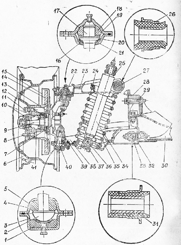
Rear leaf spring suspension of a truck:
1 - spring eyelet;
2 - rubber bushing;
3 - bracket;
4 - bushing;
5 - bolt;
6 - washer;
7 - finger;
8 - rubber bushings;
9 - spring washer;
10 - nut;
11 - bracket;
12 - rubber bushing;
13 - bushing;
14 - earring plate;
15 - bolt;
16 - clamp;
17 - root leaf;
18 - leaf spring;
19 - additional spring;
20 - stepladder;
21 - pad;
22 - rear axle;
23 - shock absorber;
24 - rubber cushion;
25 - frame spar
In the design of most trucks, trailers and buses use dependent suspension on longitudinal semi-elliptical leaf springs. In trucks and buses, the load on the rear axle can vary significantly depending on the weight of the transported cargo and the number of passengers. Therefore, the spring suspension of the rear axle, in addition to the main spring, contains an additional spring suspension. The main spring is attached by the middle part with the help of special clamps - ladders - to the bridge beam. The ends of the spring are attached to the vehicle frame by means of special brackets. Since the length of the spring changes during its deflection, one of the ends of the spring must be able to move longitudinally relative to the frame. For this purpose, special brackets with a swinging shackle, sliding and elastic supports are used.
The spring has fewer leaves than the main spring. In the middle, it is also attached to the axle beam, usually on top of the main spring, and its ends are not attached to the frame. On the frame, opposite the flat ends of the spring arm, thrust brackets are installed. When the vehicle is not loaded, only the main spring works. Under a certain load, the main spring bends so that the ends of the spring rests against the brackets, and the springs begin to work together. In this case, the total stiffness of the suspension increases.

Bus pneumatic suspension
Air suspension is often used in the suspension of modern trucks, trailers, semi-trailers and buses. The air suspension is lighter than the spring one, provides a higher ride comfort and makes it possible to adjust the distance from the load platform or the floor of the body to the road surface. This is especially important for trucks, where it is necessary to facilitate the process of loading and unloading the vehicle at ramps, storage facilities, etc. Some vehicles have special control panels for adjusting the height of the loading platform when the driver is outside the vehicle. The pneumatic suspension of buses ensures a constant floor level regardless of the number of passengers, which increases comfort and safety when getting on and off. The design of the pneumatic suspension of some buses makes it possible to further lower the floor level at stops.
Balance suspension
If adjacent axles of a multi-axle truck, trailer or semi-trailer are close to each other, a balanced suspension can be used. With such suspensions, the axles swing on the balance levers connected to them and to the springs. In this case, the springs perceive only the force of gravity of the car, and the traction and braking forces, as well as the reaction and braking moments are transmitted by the push and reaction rods. Neighboring axles rest on the ends of common springs, and the springs in the middle part are attached to the hubs, which can rotate about the axis of the balance bar fixed on the frame.
There are several types of suspension on trucks. Each type of suspension has its own design features and performance characteristics. A suspension is a set of parts that attach the wheels of a car to the body. The mechanical assembly itself includes several elements. Suspension elements reduce vibration when the vehicle crosses uneven roads. Not only vibration damping depends on the efficiency of the suspension, but also the level of damping noise from the outside that occurs when driving a car.
Features of the design of the suspension of trucks
Truck suspension the reference type must be of lightweight construction and must be made of durable materials. The main task of the suspension is to prevent roll that exceeds the vehicle's tilt limit. The body swing should not exceed the limit values during emergency braking and cornering.

Kinematic characteristics of wheels and steering must correspond operational characteristics suspension of a truck. The quality of the suspension ensures optimum wheel alignment. All car suspensions for trucks are divided into:
- Addicted;
- independent.
When choosing a suspension for installation on a truck, the elasticity of the main element must be taken into account. There are also spring suspensions and leaf spring, hydropneumatic and pneumatic, torsion bar suspensions for trucks.
All of the listed types of suspension systems for trucks have their own operating advantages. But depending on the road conditions and the characteristics of the car, there may be some disadvantages of using the suspension.
When creating a car modification, all the advantages and disadvantages of the suspension are taken into account by the designers. Today, it can be noted that truck manufacturers use different types of suspensions for the front and rear wheels of cars. The most successful type of suspension is the McPherson design. This suspension design has been in use since the 1950s.
Suspensions of cars and trucks
TO Category:
Car maintenance
Suspensions of cars and trucks
The vehicle's suspension serves to cushion shocks and shocks taken by the wheels from uneven road surfaces, dampen frame or body vibrations and reduce dynamic loads on the supporting system.
It includes three main parts: an elastic element, a damping element (shock absorber) and a guide device. In addition, the suspension passenger cars stabilizers are introduced as an additional device lateral stability.
The elastic element connects the frame to the front and rear axles or wheels and absorbs the shocks that occur when the vehicle is moving, providing the necessary smoothness. Leaf springs, springs, pneumatic cylinders and twisting elastic rods (torsion bars) are used as an elastic element.
Damping element - shock absorber is used to quickly damp vertical-angular vibrations of the frame or car body. The most widespread are telescopic double-acting shock absorbers, which dampen vibrations both during compression and tension of an elastic element.
The guiding device provides vertical movement of the wheels, as well as the transmission of pushing and braking efforts from wheels to frame or monocoque body. By the type of the guiding device, the suspensions are divided into dependent (spring and balancing) and independent (spring).
With a dependent suspension, both wheels are rigidly connected to each other by an axle suspended from the frame. In this case, the movement of one of the wheels in the transverse plane causes the movement of the other wheel.
With independent wheel suspension, each wheel is directly suspended from the frame or monocoque body and the movement of one wheel is practically independent of the movement of the other.
Rice. 1. Suspension schemes: a - dependent; b - independent
The type of suspension guiding device determines the design of the front steering axle, the basic part of which is the beam. If it is rigidly connected to the wheels, then the bridge is called continuous, and if through elastic elements, then split. On passenger cars, split front axles with independent wheel suspension are used. All trucks usually have continuous front axles and dependent suspension.
Independent suspension. On passenger cars of the GAZ family (GAZ-24-10 "Volga", GAZ -ZYu2 "Volga"), independent suspension of the front wheels of the lever type on coil coil springs is used, working in conjunction with two telescopic shock absorbers and an anti-roll bar. This suspension is an independent unit mounted on a cross member rigidly connected to the subframe. The lower and upper suspension arms are installed across the vehicle and have longitudinal rolling axes. The lower levers are connected by two hinges to the axle located in the cross member, and the upper levers are put on the axle, fixed on a special bracket. The levers are connected to the axle with rubber bushings that work in torsion and reduce the transmission of vibration to the body when the vehicle is moving.
Rice. 2. Independent pivot suspension of the front wheels
The elastic element of the suspension is a spring, which abuts the lower end against the support cup, and the upper end against the stamped head of the cross member. A double-acting telescopic shock absorber is located inside the spring and is fixed from below in the support cup, and from above, using rubber cushions, in a bracket rigidly attached to the cross member. Together with the shock absorber, its casing is also attached in the upper part. The outer ends of the upper and lower levers are connected by means of pins and threaded bushings to the upper and lower ends of the rack, in which a pivot is installed on needle bearings, secured by a pin in the pivot pin.
The wheel hub is mounted on the outer end of the stub axle on two tapered roller bearings. The vehicle's gravity is transmitted through a spring to the lower arms, strut, stub axle, bearings, hub, and through the wheel rims to the tire. When driving over bumps in the road, the lower arms lift and compress a spring that receives some of the gravity at the front of the vehicle. In this case, the movement of one wheel is practically independent of the movement of the other. The resulting vibrations of the car are damped by a shock absorber, and the dynamic travel of the suspension is limited by rubber bumpers riveted to the lower and upper arms.
To improve the stability of the car when cornering and reduce its roll, a torsion-bar anti-roll bar is installed in the front suspension, which works in torsion. It is a U-shaped bar made of spring steel and installed across the vehicle. The middle part of the rod is attached to the brackets mounted on the side members of the frame (subframe), and the ends are connected to the support spring cups through the stabilizer post and rubber pads. When the car body rolls sideways, the stabilizer bar twists and limits the body tilts, while redistributing the loads acting on the suspension springs. When the vehicle is moving sharp turns the stabilizer reduces the roll of the car by 15-25%.
Independent pivot-free lever-spring suspension of the front wheels is widely used on rear-wheel drive small class cars of the Moskvich and VAZ families. The main advantages of such a suspension include a lower mass of its unsprung parts, a decrease in the force acting in the suspension hinges, and a simple design. The structural difference of such a suspension is that it has a pivot stand rigidly connected directly to the wheel trunnion. The ends of the rack are located in the upper and lower arms on ball joints, which allow the trunnion to have angular movements in the vertical and horizontal planes.
Rice. 3. Independent pivotless front wheel suspension
The independent pivot-free suspension of the Moskvich-2140 car is assembled on a stamped beam "cross member" and is a detachable independent unit. The lower and upper levers are mounted on axles fixed to the cross member. The lower levers swing on two collapsible rubber-metal bushings, and the upper ones - on non-separable rubber-metal hinges. At the outer ends of the upper levers, collapsible ball joints are mounted, consisting of ball bearings and the heads of the ball pins of the pivot stand. The upper ball pin is inserted into the cylindrical split slot of the rack and secured with a bolt, and the lower ball pin is inserted into the tapered seat of the rack and secured with a nut. The wheel hub is mounted on the pivot of the pivot stand on two tapered roller bearings.
The elastic element of the suspension is a coil spring installed between the cross member and the lower suspension arm. Inside the spring is a double-acting telescopic shock absorber. The compression and recoil travel limitation is provided by rubber buffers attached to the arms. The suspension also interacts with the anti-roll bar. The operation of such a suspension when the vehicle is moving is similar to the operation of the suspension discussed above.

Rice. 4. Front suspension of the car VAZ-2108 "Sputnik"
The front suspension of rear-wheel drive VAZ cars has basically the same structure as the suspension of rear-wheel drive Moskvich cars. However, it is not a removable unit and can only be fully assembled on a vehicle.
On the front-wheel drive models of cars VAZ-2108, VAZ-2109 and AZLK-2141, an independent suspension of the front drive wheels is used. The main suspension element is an oscillating telescopic strut, which simultaneously acts as a guiding device and a damping element in the form of a double-acting hydraulic shock absorber.
A coil spring and a compression buffer are installed on the rack, which limit the upward travel of the wheels. Downward travel of the wheel is limited by a hydraulic recoil buffer located in the shock absorber. The upper end of the strut is connected to the body through a rubber support. The bearing 8 is installed in the support, which ensures the rotation of the rack when turning the steered wheels.
The lower part of the rack is connected by means of a bracket with a pivot pin. The wishbone is connected to the trunnion by a ball joint, to the body cross member - by a rubber-metal joint.
The anti-roll bar is attached to the lower arm and to the vehicle body bracket with rubber pads. The ends of the stabilizer, together with special arm braces, perceive traction and braking forces from the front driving wheels and transmit them to the body.
Dependent suspension. The rear and front axles of trucks and buses, as well as the rear axles of many passenger cars, have independent suspension. Its widespread use is explained by the fact that it not only softens the shocks received by the wheels from uneven roads, but also transfers traction and braking forces from the wheels to the car frame. The most common elastic element of such a suspension is the spring, which is at the same time its guiding device.
Mechanisms and units connected to the wheels through springs are called sprung parts of the car, and units and parts connected directly to the wheels (front and rear axle beams, levers, rods, etc.) are unsprung.
Consider the device of the dependent leaf spring suspension of the ZIL -130 car. The front axle of this car is suspended from the frame on two semi-elliptical springs with hydraulic shock absorbers. Each leaf spring is made up of silicon steel sheets. The first two leaf springs (large in length) are called primary. In the middle part of each leaf of the spring there are two stamped overhangs that prevent their longitudinal and lateral movement. For the same purpose, the spring sheets are tightened with clamps.
The hinge connection of the front end of the spring in the frame bracket is provided as follows. At the end of the spring, an eyelet is attached with two bolts and a stepladder through the lining. A bushing is pressed into it, through which the spring pin, fixed in the bracket, freely passes. An oiler is used to lubricate the finger.
The middle part of the spring is connected by stepladders to the beam front axle.
The rear end of the spring is located in the bracket lugs and rests on a cracker made of wear-resistant steel. With any allowable deflection of the spring, the suspension design allows it to move freely in the longitudinal direction as a result of the sliding of the root sheet along the supporting crack.
To protect the sliding root sheet from wear, an auxiliary pad is riveted at its end. The support cracker is mounted on a pin, the ends of which are located in two inserts made of alloy steel. The inserts, fixed in the bracket with a tie bolt with a spacer sleeve, serve to protect the bracket from abrasion by the ends of the springs. Spring deflections are limited by rubber buffers. The buffer is installed in a support on the frame side member, and the buffer is attached to the spring by ladders.
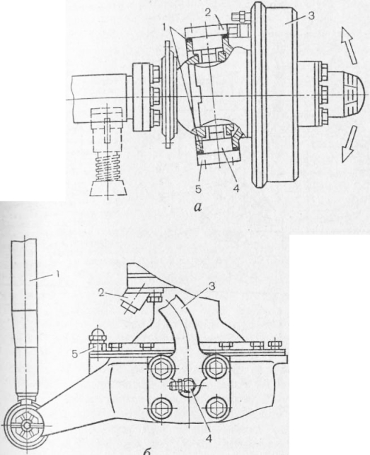
The shock absorber is pivotally connected to the front axle and frame by means of a pin and a rubber bushing. The lug rotates relative to the pin as a result of deformation of the rubber bushings.
The rear axle of the vehicle is suspended from the frame on paired semi-elliptical springs, of which two are main springs and two additional springs (springs). The main spring consists of 13 leaves, and the additional spring consists of nine. The main spring is attached to the rear axle housing with ladders with overlays. The front and rear ends of the rear main spring are attached to the frame in brackets in the same way as the ends of the front suspension.
If the car is not loaded, only the main spring works, in this case the ends of the additional spring and the brackets do not touch each other. When the car is loaded, the frame is lowered as a result of the deflection of the main spring and the ends of the additional spring abut against the brackets. In this case, both springs work. To smoothly change the stiffness of the additional spring in the initial period of its operation, the supporting surfaces of the brackets have a shaped surface.
To cushion the impact of the rear axle beam on the frame when the vehicle is operating in heavy road conditions rubber buffers are installed on the frame side members.
Many 4X2 trucks have front and rear suspensions similar to those described above. Along with this, the suspension of GAZ trucks has design feature, consisting in the fact that the main leaf springs of both the front and rear suspension do not have overhead lugs for attaching them. Root plates with frame brackets are connected using thick-walled rubber inserts (support and end). This connection does not require lubrication and also contributes to the smooth running of the vehicle.
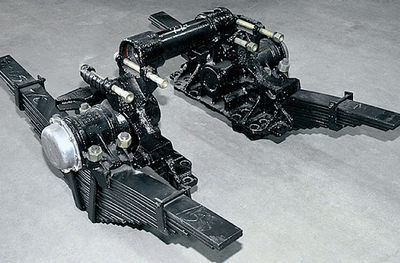
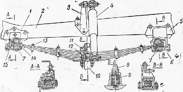
Rice. 5. Dependent suspension of a truck: a - front axle; b - rear axle
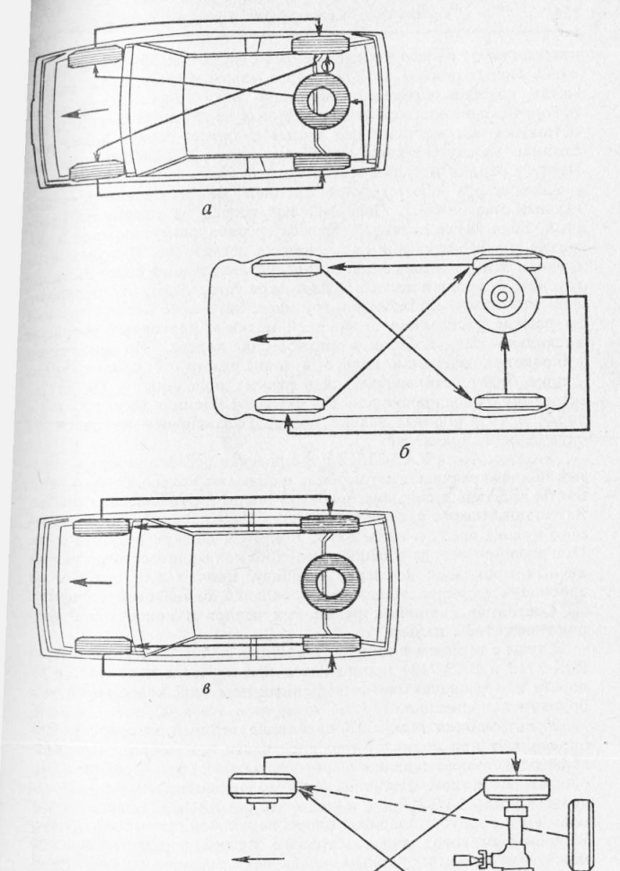
Inverted longitudinal semi-elliptical leaf springs are used in three-axle vehicles, the intermediate and rear axles of which are usually located close to each other. It is sometimes used on four-axle vehicles and multi-axle trailers. Attached to the car frame on special brackets transverse axis, at the ends of which a hub is installed in the bushings, which is attached with stepladders to the middle part of the spring. The ends of the spring rest on the brackets of the rear axle half-axle covers.
Rice. 6. Rear suspension of a three-axle vehicle
The drive axles are connected to the frame by rods that transmit pushing forces to the frame. For this purpose, each drive axle has lower brackets at the ends of the half-axle sleeves, which are connected to the frame brackets by two lower rods. In addition, an upper bracket is attached to each drive axle, which is connected by the upper rods to the frame bracket. The rods with brackets are connected by ball pins.
With a balanced suspension, both rear axles form a common bogie that can swing along with the springs on the axle, and in addition, as a result of the spring deflection, each axle can have independent movements, which ensure good adaptability of the wheels to unevenness of the road and high cross-country ability of the vehicle. When the axles are angularly displaced, the ends of the springs slide in the support brackets.
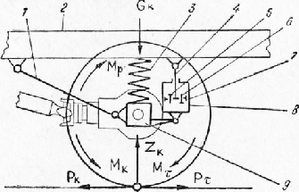
The suspension provides an elastic connection between the frame or body and the axles of the vehicle. Suspension elements and assemblies soften, together with tires, the effect on the car of the ZK loads caused by the weight of the GK car and the unevenness of the road, transfer the longitudinal force Pk, lateral forces and moment Mp from the wheels to the frame or body, damp the vibrations of the sprung and unsprung parts of the car. These functions are performed by an elastic element, a guiding device and a damping device.
Elastic elements, reducing dynamic loads, improve the smoothness of vehicles, which is characterized by the amount of compression of elastic elements under the action of a static load and the frequency of natural vibrations of the vehicle under the influence of a dynamic load (impact). The necessary smoothness is ensured when the elastic elements of the suspension of cars are compressed by 150-300 mm, and for trucks by 60-120 mm. In this case, the frequency of natural vibrations of the car should be in the range of 60-120 per minute (1-2 Hz).
By design, elastic elements are divided into metal, rubber, pneumatic, hydraulic and combined. The most common are metal elastic elements in the form of leaf springs, coil springs and torsion shafts, which are distinguished by their simplicity of design, high durability and low cost. Most vehicles use leaf springs or coil springs in combination with rubber buffers. This increases the stiffness of the suspension at the end of its compression and thereby reduces the amount of vibration of the vehicle under high dynamic loads.
Leaf springs are included in the design of the front and rear suspension of all domestic trucks and in the rear suspension of most passenger cars. The semi-elliptical leaf spring is assembled from individual curved steel sheets of various lengths. The curvature of the leaves increases from the upper longest root leaf to the lower leaf. This ensures a tight mutual adhesion of the sheets in the assembled spring and reduces the stress in the most loaded root sheet. The sheets in the spring are tightened with a central bolt or are centered with their depressions and protrusions (ZIL -130). The sheets are held against angular displacement by clamps, which are riveted from below to the ends of certain sheets and tightened with a bolt with a spacer sleeve that prevents the sheets from jamming.
Rice. 7. Suspension scheme: 1 - guiding device; 2 - frame; 3- elastic element; 4- shock absorber rod; 5 - compression valve; 6 - recoil valve; 7 - shock absorber piston; 8 - shock absorber cylinder; 9 - beam
The spring assembly is installed on the support pads or pads of the axle beam and is attached to it with two ladders through the pad. By the ends of the root leaf, the spring is connected to the frame or body spar through the brackets. Under the action of the load from the weight of the car, the spring straightens, and the distance between its ends increases, so the front end of the spring has a simple hinge connection with the spar, and the rear end has a movable connection. In passenger cars, the rear end of the spring is connected to the spar by a swinging earring, thanks to the boot, the working length of the spring, and therefore its rigidity, remains constant. In trucks, the rear end of the spring can slide in a fixed bracket, therefore, as the load increases, the working length of the spring decreases and its rigidity increases.

Rice. 8. Dependent leaf spring suspension: 1 - eyelet; 2 - brackets; 3 - spar; 4 - clamping bolt of the clamp; 5 - overlay 4; 6 - rubber buffers; 7 - shock absorber; 8 - biscuit; 9 - clamping bolt of the bracket; 10 - beam; 11 - stepladder; 12 - clamp; 13 - spring 14 - hinge pin
Rubber buffers reduce vehicle vibrations and< вышают жесткость подвески при больших динамических нагрузках.
The rear suspension of trucks undergoes significant load changes and therefore has additional small springs - springs, installed with their middle part on top of the main springs and secured by common ladders. Above the free ends of the springs, stop brackets are installed on the side members, and when the springs straighten under heavy load, the stops approach the springs and turn them on, increasing the rigidity of the rear suspension.
The end of the root sheet for pivoting has an eyelet Y with a bushing, which includes a pin connecting the spring to the bracket or shackle. The rear sliding joint of the spring transfers to it the load from the bracket through the tightening bolt 9, side pads, pin and cracker 8. Instead of the pin of the front hinge and the cracker of the rear connection, rubber cushions are used that improve the operation of the suspension (GAZ-5EA).
Corrosion resistance and wear resistance of sheets is increased due to the introduction of graphite grease between them. In passenger cars, the reduction of friction and squeak of springs is achieved by installing spacers made of non-metallic materials between the sheets.
Semi-elliptical springs perceive and mitigate the dynamic loads ZK on the car from the wheel and road irregularities, transmit to the frame the tractive force Pk and the reactive moment Mp generated by the torque Mk (or the braking moment Mx and the braking force Pt). At the same time, the springs contribute to damping vibrations, therefore, it can be considered that the springs perform the functions of elastic, guiding and damping devices.
The springs are calculated for the flexural strength and the allowable deflection, the main sheet is calculated for the strength under the action of longitudinal and twisting forces. Depending on the calculation results, the number of spring sheets can be in the range from 6 with a thickness of 6.5 mm ("Moskvich-2140") to 16 with a thickness of 10.2 mm (ZIL -130). The material of the leaf springs is high-carbon steel containing silicon, chromium, manganese. After quenching and blasting, the sheets obtain high elasticity and fatigue strength.
Coil springs are used in the front suspension of most passenger cars, sometimes in their rear suspension (VAZ-2101). Compared to a leaf spring, a spring of the same stiffness has less weight, cost and greater durability. But the spring only accepts the vertical load ZK and weakly dampens vibrations, therefore, a guide and damping device is used in the spring suspension. When calculating a spring, the torsional stresses in its coils, compression and spring stiffness are determined. The material of the spring is steel of the same type as for the high-carbon spring sheets with additions of silicon and manganese, which is hardened and blasted with shot.
The guiding device transmits longitudinal, lateral forces and moments from the wheels, and also determines the nature of the movement of the wheels when the elastic elements are compressed. By the type of mutual influence of the movement of the wheels of one axle, there are dependent and independent suspensions.
The dependent suspension provides for a rigid connection of the wheels with a solid axle, so that the movement of one wheel when hitting an unevenness is transmitted to the entire axle and to the other wheel. This suspension is simple in design, but when driving on uneven roads causes significant body vibration. This led to its application for the front and rear axles of all domestic trucks, as well as for the rear axles of most passenger cars.

Rice. 9. Independent lever-spring suspension: 1, 11 - rubber buffers; 2 - cup; 3- stabilizer rack; 4- lower arm; 5 - the axis of the lower arm; 6 - rubber bushing; 7 - U-shaped bar; 8- sub-frame spar; 9- cross member; 10- spring; 12 - the axis of the upper lever; 13 - upper arm; 14 - cross member head socket; 15 - suspension strut; 16 - shock absorber; 17 - kingpin; 18 - pivot pin
The independent suspension is characterized by the use of a composite axle, when each wheel is connected to the frame independently and one moves independently of the other. This reduces stiffness, suspension and axle swing at high travel speeds, which greatly improves stability and ride comfort. Therefore, independent suspension is used for the front wheels of all passenger cars.
The most widely used lever-spring independent suspension with transverse swinging levers (Fig. 12). The basis of the suspension is a cross member screwed to the side members of the sub-frame and having a lower and an upper axle. On these axes, the lower and upper levers are pivotally mounted with their inner ends, and their outer ends are pivotally connected with the upper and lower heads of the rack. Two additional lugs of the rack have coaxial holes for the king pin, which simultaneously enters the holes of the pivot fork. A cup with a seat is screwed to the lower levers, into which the lower end of the spring enters, and the upper end of the spring rests against the inner seat of the cross-member head.
With a push from a bump in the road, the wheel rises, rotates the levers around their axles and compresses the spring, due to which most of the energy of this push is absorbed and not transferred to the body. At increased loads and significant wheel lift, the rubber buffer approaches the head stop and is activated, increasing the suspension rigidity and limiting wheel lift. Reverse move wheels are limited by a buffer.
The arrangement of the axles and the length of the levers provide a slight change in the distance between the wheels (track) when moving them and the correspondence between the change in the camber angle and the toe angle. This achieves good stability and controllability of the vehicle.
The anti-roll bar links the suspension of one and the other wheel with some stiffness, which reduces body roll and lateral vibrations. It consists of a U-shaped bar, middle part which is connected to the side members through rubber bushings with clips and brackets, and the ends are connected through rubber cushions with struts and cups. When lifting one wheel or increasing the load on it (for example, when cornering), the stabilizer bar, resisting twisting, transfers the load to the suspension of the other wheel. This reduces the difference in wheel lift, thereby reducing body roll and swing. If the movement of the wheels is the same, then the stabilizer does not come into operation.
An independent lever-spring suspension can have a pivotless design, where instead of a pivot pin with a fork and holes for a kingpin, a pivot stand with holes in the lower and upper parts for the pins of the ball joints of the lower and upper suspension arms is used (VAZ-2101, "Moskvich-2140") ... Ball joints provide swinging of the levers in the vertical plane and rotation in the horizontal plane of the rack, stamped together with the axle of the wheel. This eliminates the pivot connection, which allows you to reduce the number of parts and the total weight of the suspension, to reduce the number of points of its lubrication.
Grease independent suspension it is necessary for the normal operation of the hinges of the levers, the king pin and is made through the May-Lenki. Some hinges have rubber bushings and therefore require no lubrication.
Levers, strut, pivot axle are loaded by the vertical force of the vehicle weight and horizontal forces during acceleration, braking or cornering. The strut is subjected to additional torsional load from the braking torque, which is absorbed by the hinges of the levers. Taking these loads into account, the levers, strut and axle are designed for flexural strength, in addition, the upper levers are designed for compression, the lower ones for tension. The material of the levers, struts and trunnions are medium-carbon low-alloy steels with small amounts of chromium, nickel, and molybdenum.
The pivot is designed for bending, crushing and shear strength, and is made of low-carbon low-alloy or medium-carbon steels with subsequent hardening.
The damping device provides a rapid reduction in vibration of the vehicle on the elastic suspension elements under the action of a dynamic load. The most common damping device is a telescopic double-acting hydraulic shock absorber, which creates resistance to compression and expansion (recoil) of elastic elements. Resistance is created by converting mechanical vibration energy into dissipated thermal energy due to the viscosity and friction of the fluid in the shock absorber. Shock absorbers increase stability, controllability, ride smoothness and are installed in the front suspension of trucks, as well as in the front and rear suspension of passenger cars.
The shock absorber cylinder is pivotally connected to the beam 9 and filled with shock absorber oil. The cylinder contains a piston with a compression valve and a recoil valve, the piston rod is pivotally connected to the frame or body. During oscillations of the body or wheel on the suspension, the piston in the cylinder reciprocates. When the suspension is compressed, the piston goes down, the oil pressure under it increases, due to which the compression valve opens and the oil is forced into the cavity above the piston. When the suspension recovers, the piston goes up, the recoil valve 6 opens, and the oil flows from the upper to the lower cylinder cavity. The resistance to oil flow through the valve bore sections during the piston movement damping the vibrations of the vehicle on the suspension.
The resistance of a shock absorber is related to the speed of movement of its piston, this relationship is called the characteristic of the shock absorber. When compressed, the shock absorber resistance should be 2-5 times less than the recoil resistance, so as not to cause significant suspension stiffness when transferring shocks and impacts from the wheels to the body.
The calculation of the shock absorber consists in determining the flow sections of channels and valves to obtain the required characteristics and choosing overall dimensions providing normal thermal conditions, in which the temperature of the shock absorber should not exceed +100 ° С.
Suspension of the car VAZ-2101. Front suspension, independent, pivotless, mounted on a stamped-welded cross member screwed to the body side members. The correct position of the cross member is determined by the adjusting plates between the cross member bracket and the side member. The axle of the lower arm is screwed to the lower part of the cross member through the adjusting washers with two bolts. The camber angle of the wheels is adjusted by the same change in the number of washers under both bolts. The same washers allow you to adjust the caster angle of the pivot axis, which requires special equipment. The axle of the upper arm looks like a long bolt and is installed in special body brackets with a spacer sleeve between them.
The lower and upper arms are stamped from sheet steel, and each has a triangular contour, the inner side of which is made in the form of a fork with holes for hinged installation on the axle. The outer top has a hole for attaching a ball joint or a pivot post. This design provides the required rigidity and strength of the levers when transmitting to the body longitudinal, lateral forces and moments from the wheels. The anti-roll bar bracket and spring cup are welded to the lower arm. In the hole of the cup there is a lower shock absorber bracket fixed to the lever.
The articulated connection of the levers and axles is made on rubber-metal bushings (silent blocks), consisting of a rubber insert, a pressed-in steel tube and a pressed-on steel cage. Silent blocks are pressed into the holes of the forks of the levers and are fixed on the axes of the levers with nuts. Thus, when the lever is turned, the outer cage of the silent block rotates relative to its inner tube on the axis due to the elasticity and internal friction of the rubber insert. There is no external friction of surfaces in the hinges, which significantly increases their durability and eliminates the need for lubrication.
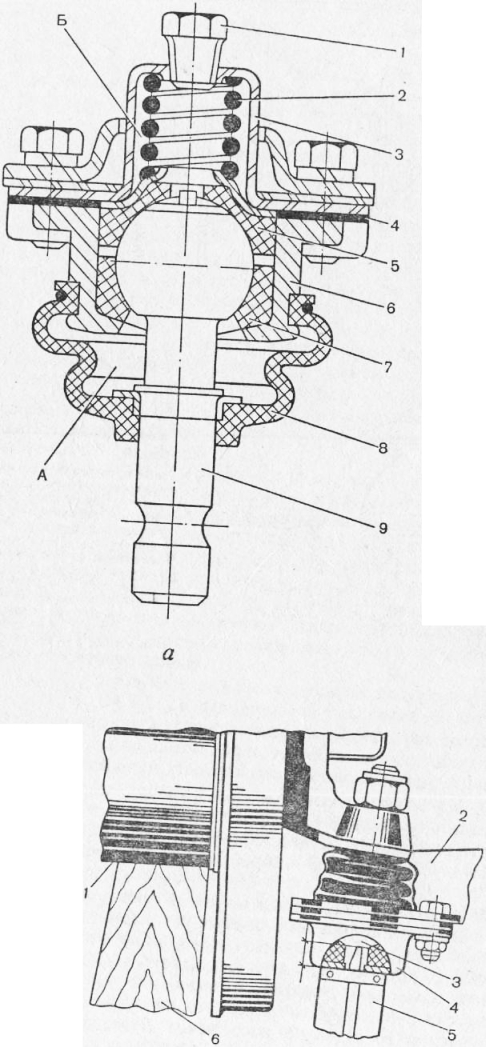
Ball joints are non-separable, have differences in design, since the lower joint takes a large load from the braking torque, steering rod and the weight of the car on the front axle. Its hemispherical pin rests on a rubber insert, the working surface of which is coated with a layer of nylon with the addition of Molybdenum Disulfide, which significantly reduces wear on the mating. The liner is in the cage, and due to the elasticity of its special rubber, it is constantly pressed against the head of the finger, preventing the appearance of a gap in the process of wear of the mating. A cermet bearing sleeve is installed on top of the pin, which with its inner surface is paired with the pin, and the outer hemispherical surface is paired with the hinge housing. The outer surface of the bushing has grooves to improve lubrication.
Rice. 10. Front suspension of the car VAZ-2101: 1 - insert; 2, 17 - ball fingers; 3, 20 - clips; 4, 19 - hinge bodies :. 5, 18 - bushings; 6 - wheel disk; 7 - swivel stand; 8 - guide pins; 9 - the axis of the pivot rack; 10 - hub bearings; 11 - wheel bolt; 12 - oil seal; 13 - brake caliper bracket; 14 - brake disc; 15 - casing; 16 - ring; 21 - washer; 22 - upper hinge; 23 - upper arm; 24 - spring gasket; 25 - spring cushion: 26, 31 - silent blocks; 27 - the axis of the upper lever;. 28 - body spar; 29 - adjusting plates; 30 - cross member; 32 - adjusting washers; 33 - axis of the lower arm; 34 - shock absorber; 35 - spring: 36 - shock absorber mounting bolt axle; 37 - shock absorber mounting bracket; 38 - lower arm; 39 - protective cover; 40 - lower hinge; 41 - wheel hub
The upper hinge has a pin with a hemispherical shoulder, with which the pin rests on the cage through a rubber ring and a hemispherical steel washer. The bearing bush, the same as that of the lower hinge, is put on the pin and works in tandem with the housing.
After assembling the hinges, the body and the yoke are connected by spot welding. The internal cavity of the hinges is filled with grease through the hole closed with a plug and is protected from dust and moisture rubber cover.
The assembled hinges are fastened in the holes of the lever with three bolts each. Ball pin shanks are tapered and threaded to fit and secure in the holes in the pivot arm.
The suspension spring with its lower end rests through a steel gasket on the lower arm cup, with its upper end rests against a special body bracket through a rubber gasket. Depending on the stiffness under a load of 435 kg, the springs are divided into two groups at the factory. With a length of more than 232 mm, the springs are marked with yellow paint on the outer surface of the middle coils and belong to group A. If the length is less than or equal to 232 mm, the spring is marked with green paint and included in group B. The springs of the same must be installed in the front and rear suspension the same group. As an exception, it is allowed to install group A springs in the front suspension and group B springs in the rear suspension.
When the wheel rises significantly and the spring is compressed, the upper lever rests with its platform against a rubber buffer fixed in a special body bracket. The reverse travel of the wheel when the spring recovers is limited by a plastic buffer in the form of a sleeve on the front shock absorber rod (Fig. 11).
Shock absorber, telescopic, double-acting, in the front suspension located inside the spring. Its lower part is pivotally fixed to the lower arm bracket, and the upper part is connected to the body bracket through rubber cushions (Fig. 10). The lower hinge is a rubber bushing with a tube and a cage, pressed into the eyelet of the shock absorber body (silent block) (Fig. 11). When installed on the bracket, an axle-bolt is inserted into the holes of the bushing and bracket, on which the bushing is tightened with a nut. Due to its elasticity, the bushing allows the shock absorber to rotate about the axle.
Front and rear shock absorbers are identical in design, differing in length, mount, travel and performance. The shock absorber consists of three main assemblies: the body 19 assembled, the working cylinder 18 assembled and the rod 23 assembled.
Rice. 11. Shock absorber of the car VAZ-2101: 1 - hinge tube; 2 - bushing; 3 - hinge holder; 4- body lug; 5- compression valve body; 6 - compression valve spring; 7 - axial hole of the compression valve; S - radial opening of the compression valve; 9 - compression valve; 10 - inlet valve; 11 - recoil valve nut; 12 - spring of the recoil valve; 13 - holes in the piston for the recoil valve; 14, 29 - sealing rings; 15 - bypass valve; 16 - limiting plate; 17 - buffer; 18 - working cylinder; 19 - shock absorber body; 20 - capillary hole; 21 - casing; 22 - housing nut; 23 - stock; 24 - spacer sleeve. ka; 25 - cover; 26 - protective ring; 27 - gasket; 28 - stem oil seal; 30 - rod guide; 31 - drainage tube; 32 - spring of the bypass valve; 33 - holes in the piston for the bypass valve; 34 - recoil valve; 35 - piston; 36 - compression valve seat; 37 - intake valve spring; 38 - hole for the inlet valve
The cylindrical body is closed from below with a welded eyelet with a silent block, a nut with wrench holes is screwed into it from above.
The working cylinder has a pressed-in compression valve body from below, into the central hole of which a seat with a compression valve pressed by a spring is screwed. The seat through the restrictive plate and the spring presses the inlet valve against the holes. On top of the cylinder is a cermet rod guide with a capillary hole, a drain tube and a rubber O-ring. In the guide there is a rubber rod gland, the cage of which is pressed with a nut through a polyurethane gasket and a protective ring. At the same time, the nut grips the cylinder with the compression valve body in the lug bore.
The stem is chrome-plated, polished and has a cover at the upper end, which is fixed by a pressed-on spacer sleeve. A casing is welded to the cover to protect the stem from dust, moisture and damage. At the lower end of the rod, there is a sintered piston with a rubber O-ring and through holes located in two circles. The holes on the inner circumference are closed by a recoil poppet valve, which is pressed by a spring that rests against the nut collar screwed onto the stem. The openings on the outer circumference are closed by a poppet relief valve under the action of a restraining poppet spring.
For normal operation of the shock absorber, it is necessary that the entire volume of the cavities under the piston, above the piston and the lower part of the reservoir between the cylinder and the shock absorber housing are filled with oil.
Compressing the suspension spring as the wheel rises causes the shock absorber rod and piston to move downward, creating pressure on the oil under the piston. Due to this, the bypass valve opens, and due to the low stiffness of its spring, oil flows with little resistance through the holes from the bottom to the upper cylinder cavity. In this case, a part of the upper cavity is occupied by the volume of the rod introduced into it, due to which all oil from the lower cavity cannot flow into the upper one. This "surplus" of oil, when the shock absorber piston moves slowly, flows out through the small axial bore of the compression valve into the reservoir between the cylinder and the shock absorber housing. With a sharp compression of the suspension and rapid movement of the shock absorber piston, the oil pressure under the piston increases, and the compression valve opens, overcoming the significant stiffness of its spring. Oil can escape into the reservoir through the radial hole 8 of the valve, the degree of opening of which depends on the speed of the piston. Thus, the resistance of the shock absorber to compression is determined by the bore diameter, the spring rate, and the degree of opening of the radial bore of the compression valve, which determines the compression performance of the shock absorber.
Suspension recoil and upward movement of the piston rod increase oil pressure above the piston. When the piston moves slowly, oil enters the holes and through the grooves of the valve disc into the lower cavity. The rapid movement of the piston opens the recoil valve, overcoming the increased stiffness of its springs, and oil flows into the lower cylinder cavity. Due to the presence of a rod in the upper cavity, the oil flowing into the lower cavity is insufficient to fill it, and a slight vacuum is created in it. As a result, the inlet valve with a spring of low stiffness opens, and oil with low resistance enters the lower cavity from the reservoir. The characteristics and resistance of the shock absorber to recoil are determined by the size of the holes, valve grooves and the stiffness of the spring.
Compression of the shock and downward movement of the piston creates a slight vacuum over the piston, which can lead to air being sucked in through the stem seal. Air bubbles and oil vapors in the shock absorber cylinder distort its performance and disrupt normal operation. To prevent air from sucking into the cylinder, the cavity above the piston communicates with the reservoir through a capillary hole and a polyethylene tube through which oil can be sucked into the cylinder. If air and oil vapors enter the cylinder, then when the shock absorber recovers, they are discharged through the same hole and tube into the reservoir and accumulate in its upper part, without affecting the characteristics of the shock absorber.
The swivel stand has two tapered holes for seating ball pin shanks. A swivel arm is attached to its flange from the inside, a brake caliper bracket and a protective casing from the outside. Tapered roller bearings are installed on the axis of the pivot stand, pressed into the hub and secured with a nut with a lock washer. For bearings, grease is put in the hub, which is held by a pressed-in oil seal and cap. The brake disc is screwed to the hub with two screws in the form of guide pins. The wheel is mounted on them with its disc and, together with the brake disc, is attached to the hub by four bolts with tapered centering surfaces.
The rear suspension is dependent, spring, with reaction rods, its elements and assemblies are connected by a beam of the rear driving axle. The jet rod system transmits to the body longitudinal and lateral forces, moments from the wheels and consists of two lower, two upper longitudinal rods and a transverse rod. The longitudinal rods transmit traction, braking forces and their moments, the transverse rod transmits lateral forces. The transverse and lower longitudinal rods are made of pipes with inserted and welded lugs, the upper rods are made of a bar with lugs welded to the ends. All rods are pivotally connected to the drive axle beam brackets and to the body brackets. Hinges I consist of two tapered rubber bushings, pressed into the eyelet, with a tube and washers held by flaring the tube. The hinges are connected to the brackets with axles in the form of bolts and are finally tightened with nuts to a torque of 8 kgm on a car with full load.
Suspension springs are installed with their ends in support cups welded to the drive axle beam and the body. The spring rests on the lower cup through a plastic gasket, on the upper cup - through a rubber gasket. As with the front suspension, the springs are set according to their stiffness. Under heavy loads and compression of the spring, the lower cup rests against a rubber buffer located inside the spring and fixed in the upper cup. In this case, the limitation of the lifting of the driving axle is provided by a rubber buffer fixed in the body bracket above the middle part of the axle, which does not allow cardan shaft touch the body floor. The reverse travel of the bridge is limited by shock absorbers.
The rear shock absorbers are mounted on two tapered rubber bushings. The shock absorber is connected by the lower eyelet with the drive axle beam bracket, the upper one - with the body bracket. The inclined arrangement of the shock absorbers provides the required amount of suspension travel and increases the lateral stability of the body.

Rice. 12. Rear suspension of the car VAZ-2101: 1 - lower longitudinal bar; 2- upper longitudinal bar; 3- buffer; 4 - spring; 5 - body base bracket; 6 - shock absorber; 7- beam; 5 - transverse bar; 9 - beam bracket; 10 - support cups; - the hinge of the rod; 12 - bushing; 13 - washer; 14 - bar eye; 15 - hinge tube
Suspension of the car "Moskvich-2140". The front suspension is independent, pivotless, basically corresponds to the design of the front suspension of the VAZ-2101 car and has some features (Fig. 13). The stamped-welded cross member is bolted to the frame side members through rubber gaskets and bushings, which reduces vibrations transmitted to the body. The cross member is bent in the horizontal plane, and the axes of the levers fixed on it are located at an angle of 15 ° to the longitudinal axis, which made it possible to improve the placement of the engine.
The lower and upper levers are mounted on axles in silent blocks. There are spacers between the axle of the upper arm and the cross member support to adjust the camber angle. A bracket is installed under the axle mounting bolts, which allows you to adjust the caster angle of the pivot axis. An anti-roll bar bracket and a rubber buffer-stop bracket are welded to the lower arm.
Collapsible ball joints. The pin of the lower hinge has a cracker, which with its end and inner surface is paired with the pin, and the outer hemispherical surface is paired with an insert pressed into the body of the hinge. From below to the spherical surface of the finger, a small force of the spring presses the holder, which, resting against the bottom end of the cover, prevents the finger from moving down. A grease nipple is screwed into the cover. The taper shank of the pin is secured in the hole of the pivot stand with a nut.

Rice. 13. Front suspension of the car "Moskvich-2140": 1 - cross member; 2 - spring; 3 - spring gasket; 4 - shock absorber; 5, 39 - silent blocks; 6 - the bolt of the upper arm axle; 7 - the axis of the upper lever; 8, 15 - shims; 9 - upper arm; 10, 21 - rubber buffers; 11 - upper hinge;. 12 - liner spring; 13 - cork; 14 - push insert; 16, 33 - hinge bodies; 17 - body insert; 18, 30 - ball fingers; 19 - coupling bolt; 20 - swivel stand; 22 - ball pin nut; 23 - wheel hub; 24 - hub bearings; 25 - bearing nut; 26 - wheel nut; 27 - screw for fastening the brake disc; 28 - brake disc; 29 - lower hinge; 31 - insert; 32 - spherical biscuit; 34 - clip; 35 - cover; 36 - oiler; 37 - shock absorber lower bracket; 38 - bushings; 40 - lower arm; 41 - the axis of the lower arm
The upper hinge has a pin with a ball head resting on a polyamide insert pressed into the hinge housing. The spring presses the pressure insert from above to the head of the finger. There are shims between the surface of the lever and the flange of the body to eliminate the axial play of the pin. Grease is put into the hinge through the plug. The shank of the pin is locked with a tie bolt in the blind hole of the pivot stand.
The hinges are bolted to the levers and protected from dust and moisture with rubber covers.
The suspension spring is installed between the lower arm and the cross member cup, which has a rubber gasket. According to the stiffness, the springs are divided into three groups and are designated by one, two or three risks on the reference coil. On the left and right sides of the suspension, it is necessary to install springs of one of three groups.
The shock absorber is telescopic, double-acting, its design and operation are close to the described shock absorber VAZ-2101. The front shock absorber does not have a protective cover, the rear shock absorber differs in length, mounting, travel and characteristics.
The swing arm has an axle and a flange to which the brake caliper and swing arm are attached. A hub with five pressed-in bolts rotates on the axle bearings. The oil seal and the cap keep the grease in the hub, the tightening of the bearings is adjusted with a nut. The brake disc is screwed to the hub with two screws, and then, together with the wheel disc, is attached to the hub bolts with flare nuts.
The rear suspension is dependent on longitudinal semi-elliptical springs. The sheets in the spring are tightened by a central bolt, the head of which enters the cushion hole on the rear axle beam, fixing the position of the spring. The clamps are installed on the pins of the third and fifth sheets. The rubber gaskets of the clamps together with the polyethylene washers between the ends of the sheets prevent the springs from squeaking during operation. The spring assembly is installed on the cushion from the bottom of the rear axle beam and is attached to the beam with stepladders. Stepladders cover the beam from above through the buffer holder, at the bottom they pass through the holes of the lining and with nuts secure the springs.
The lug-shaped front end of the root sheet has a pressed and expanded thin-walled bushing that improves the working conditions of the two rubber bushings. The eyelet with bushings is pivotally connected by means of a pin with a bracket on the side member of the body base. The finger in the hole in the inner cheek of the bracket is fastened with a nut, in the large hole in the outer cheek the finger has two convex washers. When tightening the nut, the rubber bushings get an interference fit in the eyelet and on the pin, after which the washers, resting on the step of the pin, straighten and secure the pin in the hole in the outer cheek of the bracket.
The rear eyelet of the root leaf is connected to the spar by a swinging earring. Two fingers are pressed into the outer cheek of the earring, which fit into rubber bushings installed in the rear eyelet and a bushing welded into the body side member. The inner cheek and nut create the necessary tension on the rubber bushings. With a significant deflection of the spring, a hollow rubber buffer enters into operation, an additional buffer limits the lifting of the axle.
![]()
Rice. 14. Rear suspension of the car "Moskvich-2140": 1 - spring; 2, 18 - rubber buffers; 3 - clamp gaskets; 4 - clamp; 5 - washer; 6 - shock absorber mounting bolt; 7 - silent blocks of the shock absorber; 8 - shock absorber mounting pin; 9 - earring; 10 - shock absorber; 11 - beam; 12 - beam pillow; 13 - tie bolt; 14 - step-ladder nut; 15- spring pad; 16 - stepladder; 17 - buffer holder; 19 - spar bushing; 20 - earring nuts; 21 - earring fingers; 22 - spring ear pin; 23, 27 - nuts for fastening bushings and pins; 24 - washers for fastening bushings and pins; 25 - spring eyelet bushing; 26 - side member bracket
The rear shock absorbers are tilted and mounted in rubber bushings. The lower eyelet includes a finger pressed into the lining hole, the upper eyelet is bolted to the body bracket.
Suspension of the GAZ-24 "Volga" car. The front suspension is independent, pivot, mounted on a forged I-section, screwed to the side members. To increase rigidity, the cross member is additionally connected to the base of the body by a brace in the form of a rod with threaded ends. The lower and upper levers are installed with their "inner" ends in silent blocks on the axles of the cross member. The upper axle is screwed to the crosshead head through two sets of shims. By changing their number in both sets, the camber angle of the wheels is regulated, by shifting from one set to another - the caster angle.
Rice. 15. Front suspension of the car GAZ-24 "Volga": 1 - brake drum; 2 - wheel disc; 3 - an adjusting washer; 4 - screw for fastening the brake drum; 5 - kingpin; 6- pin; 7 - cap; 8 - bearing nut; 9 - hub; 10 - stuffing box; 11 - wheel nut; 12 - thrust bearing of the king pin; 13 - pivot needle bearing; 14 - internal threaded bushings; 15 - external threaded bushings; 16 - pins of the hinges of the rack; 17 - sealing rings; 18 - rack; 19 - sealing cap; 20, 34 - rubber buffers; 21 - upper arm; 22 - spring gasket; 23 - shock absorber casing; 24 - shims; 25 - the axis of the upper arm; 26 - silent block; 27 - spar; 28 - cross member; 29 - the axis of the lower arm; 30 - lower arm; 31 - spring; 32 - support spring cup; 33 - shock absorber; 35 - locking pin; 36 - pivot arm; 37 - plug; 38 - brake shield
The outer ends of the levers are connected to the rack by threaded hinges. The outer threaded bush is pressed into the column head, the inner threaded spacer with grooved ends is clamped between the ends of the levers with a nut and pin. When the levers swing together with them, the inner sleeve rotates along the thread of the stationary outer sleeve in the column head. Threaded joints are lubricated with grease fittings and sealed with rubber rings. The strut is connected to the pivot pin by a pivot, which is fixed in the holes of the trunnion fork with a locking pin and together with it rotates in the needle bearings of the strut tides. From the inside, the bearings are sealed with rubber rings, from the outside they are closed with plugs. The vertical load is supported by a thrust ball bearing in a cage, which has a rubber sealing cap. Needle and ball bearings are lubricated through grease fittings. The axial clearance in the pivot joint is determined by an adjusting washer.
The bottom end of the spring rests against the cup screwed to the lower levers, and the top end rests against the cross-member support through the rubber gasket. When the wheel is raised and lowered significantly, rubber buffers 20 and 34 begin to work together with the spring. Anti-roll bar struts are attached to the spring cup.
The shock absorber is telescopic, double-acting, with a rubber protective cover. Rear shock absorber differs in length, fastening of the lower end, stroke size and characteristics.
The pivot pin has an axle and a flange with a screwed pivot arm and brake shield. The hub, mounted on roller bearings, has an oil seal and a cap that retain the lubricant, nut 8 is used to adjust the tightening of the bearings. The brake drum is mounted on bolts pressed into the hub, screwed on with three screws and finally fastened together with the wheel disc with flare nuts.
The rear suspension is dependent on longitudinal semi-elliptical springs. Its design has no fundamental differences from the rear suspension of the Moskvich-2140 car. A feature of the suspension is the presence of rubber cushions with clips between the spring, rear axle beam and pad 8.
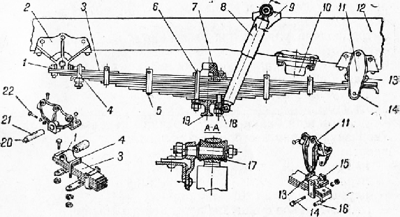
The suspension of the GAE-53A car is dependent on longitudinal semi-elliptic springs. The front suspension has 12 leaf springs tightened with a center bolt and four clamps. The spring assembly is attached to the support platform of the axle beam with two ladders with nuts. Stepladders cover the beam from above through a cage of rubber buffer-limiter 8. To the ends of the first and second root sheets, cups for rubber cushions are riveted through which the spring rests on brackets riveted to the spar. From below, covers are screwed to the brackets, clamping the rubber cushions. The upper and lower airbags at both ends of the spring transmit vertical loads, the front end airbags transmit the braking force, and the thrust airbag - the tractive force. The rear end of the spring, when it is deflected and straightened, can move between the pillows in the bracket. During assembly, graphite grease is placed between the leafs of the spring.

Rice. 16. Rear suspension of the car GAZ-24 "Volga": 1 - spar bracket; 2 - rubber buffers; 3 - shock absorber; 4 - beam; 5-rubber cushions; 6 - spring; 7 - earring; 8 - spring pad
Rice. 17. Front suspension of the GAE-53A car: 1 - front spring bracket; 2 - spar; 3 - shock absorber bracket; 4 - shock absorber; 5 - rear bracket springs; 6, 14 - cups of pillows; 7 - spring cushions; 8 - rubber buffer; 9 - spring clamping bolt; 10 - beam; And - buffer clip; 12 - stepladder; 13 - spring clamp; 15 - persistent pad
Telescopic shock absorbers, double-acting, installed only in the front suspension. The upper lug with rubber bushings is fixed on the bracket pin, the lower one - on the pin screwed to the axle beam.
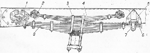
The rear suspension includes leaf springs and leaf springs (Fig. 18). Each spring is held together by its own center bolt and clamps. The springs are lined and covered from above by ladders through the pad. A spring with a sprung is installed on the cushion of the rear axle beam and is fastened through the pad with step-ladder nuts. The ends of the spring are supported by brackets via rubber pads, just like in the front suspension. Under load, the free ends of the upper sheets of the springs abut against the rubber cushions screwed to the brackets. The deflection of the springs and the upward travel of the rear axle are limited by a rubber buffer, on the gasket screwed to the side member from below so that the axle beam rests against the buffer.

Rice. 18. Rear suspension of the car GAZ -63A: 1 - front spring bracket; 2 - sprung cushion; 3 - suspension bracket; 4 - sprung pad; 5 - stepladder; 6 - sprung; 7.9 - tie bolts; 8 - sprung lining; 10 - rear spring bracket; 11 - spring; 12 - overlay of stepladders; 13 - rubber buffer
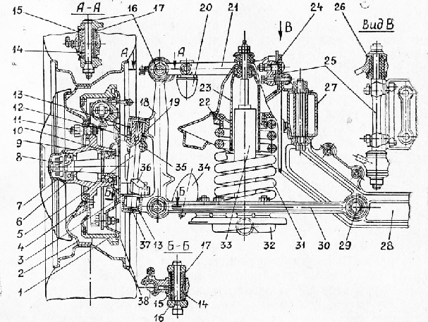
The suspension of the ZIL -130 car is dependent on longitudinal semi-elliptic springs. The front suspension has 11 leaf springs, which are centered by their valleys and protrusions, tightened with clamps. The spring with a rubber buffer pad is covered by ladders and is attached to the support platform of the axle beam with nuts. The front end of the root leaf has an overlay, to which an eyelet with a bronze bushing is attached with a stepladder and two bolts. The eyelet is connected to the bracket with a pin, which is locked in the bracket holes with two tie bolts. The pin surface is lubricated through an oiler, axial and radial channels. The rear end of the root sheet with an overlay can be moved in the bracket between the support cracker and the tie bolt sleeve. The support cracker is installed on a pin fixed in the side inserts, which are connected to the bracket with a tie bolt.
The shock absorbers are installed only in the front suspension and are secured by lugs with rubber bushings on the pins of the upper and lower brackets.
The rear suspension consists of leaf springs and leaf springs (fig. 20).
Rice. 19. Front suspension of the car ZIL -130: 1 - spring eyelet; 2 - front spring bracket; 3 - spring pad; 4 abalone stepladder; 5- spring clamp; 6- spring step-ladder; .7, 10 - rubber buffers; 8 - shock absorber; 9 - upper shock absorber bracket; 11 - rear spring bracket; 12 - frame spar; 13 - supporting cracker; 14 - clamping bolt of the bracket; 15 - side insert; 16 - tie bolt sleeve; 17 - shock absorber mounting bushings; 18 - shock absorber lower bracket; 19 - beam; 20 - oiler; 21 - ear finger; 22 - tightening bolt of an eyelet
Rice. 20. Rear suspension of the car ZIL -130: 1 - front spring bracket; 2 - suspension bracket; 3 - stepladder; sprung; 5 - rear spring bracket; 6 - supporting cracker; 7 - side insert; 8 - spring
1. Check the fastening of the axles of the front suspension arms.
2. Check the attachment of the levers on the axles through one TO-2.
3. Check the fastening of the brake shields through one TO-2.
4. Check the fastening of the spring bracket covers.
5. Check the riveted frame joints, paying particular attention to the fastening of the spring brackets.
6. Check the adjustment of the front wheel hub bearings (for a ZIL -130 car - after one TO-2).
To do this, raise the front axle, remove the hub cap, unscrew the adjusting nut by half a turn and check if the wheel rotates freely. Tighten the nut with a spanner of 200-400 mm, turning the wheel in both directions. When turning the wheel tightly, loosen the nut by 1 / 5-1 / 3 turn and check the tightness of the bearings. The wheel should rotate freely without axial and radial play. In this position, the adjusting nut locks, and if, after driving 8-10 km, the hub does not receive noticeable heating, the adjustment is considered complete.
Before adjusting the bearings through one TO-2, replace the grease in the wheel hubs. To do this, remove the hub, rinse with kerosene and put in it 0.1-0.25 kg of Constalin 1-13 or Litola-24 (VAZ-2101). Then install the hub and adjust the tightening of its bearings as described above.
Check wheel alignment
Before checking and adjusting the angles, it is necessary to set the normal pressure in the tires, check the tightness of the front wheel hub bearings, eliminate the backlash in the hinges of the suspension and steering rods. Then you should ensure the nominal load of the car and, after moving it a few meters, place it on a level, horizontal platform. The wheels must be in a straight-ahead position.
First, the angle of caster of the pivot axis or the axis of rotation of the wheels is adjusted, then the angles of camber, toe and maximum rotation. The most accurate adjustment is carried out on a special stand, but you can use the simplest methods.
The caster angle of the main swing on a VAZ-2101 car is adjusted by changing the number of washers under one or the other bolt of the axle of the lower suspension arm. On the "Moskvich-2140" car, this angle is adjusted by rearranging the adjusting bracket from one to the other the bolt of the upper arm axle. To check this angle, you need a special device or stand. On a GAZ-24 "Volga" car, the caster angle of the pivot axis can be checked indirectly using a plumb line. If the plumb line touches the front end of the upper head of the suspension strut, then it should pass at a distance of 26-31 mm from the front end of the lower head of the strut. This angle is adjusted by changing the number of spacers under one or the other bolt of the upper arm axle.
The camber is checked indirectly using a plumb line on the outer side surface of the tires. First, it is necessary to find the points of equal lateral runout of the tires and install the car so that these points are on the common vertical. The difference between the lower and upper distance from the side surface of the tire to the plumb line must be in the range of 1 to 5 mm. The camber angle is adjusted by the same change in the number of the same gaskets under both bolts of the lever axles.
To facilitate the adjustment of the caster and camber angles, you can relieve the suspension arms by lifting the front of the car and compressing the suspension spring with a special tie.
Toe-in is related to wheel alignment, so after adjusting caster and camber, be sure to check and adjust wheel alignment with a ruler. First, the horizontal distance between the inner side surfaces of the tires at the level of the wheel centers is measured at the front, and the measurement points are marked. Then the car rolls forward so that the marked points are at the same level behind, and the distance between them is measured again. The difference between the second and first measurements gives the convergence value. The convergence of the wheels of passenger cars is regulated by changing the length of the side steering rods by turning their couplings. In trucks, this adjustment is made by turning the tie rod relative to the ends, which also changes its length.
The angle of rotation of the wheels must ensure the required turning radius of the vehicle without touching the wheels for the suspension parts and side members. It is characterized by the angle of maximum rotation of the inner wheel, while the steering drive ensures the rotation of the other wheel by a certain smaller angle. For VAZ-2101 and GAZ-24 "Volga" cars, the angle of maximum rotation is 39 °, it is not adjustable and is due to the position of the protrusions-stops on the steering bipod. On the Moskvich-2140 car, this angle is 35 ° and is regulated by bolts in the side member brackets, which abut against the protrusion of the steering arm or pendulum arm. For GAZ -53A and ZIL-130 cars, the wheel rotation angle is 34 ° (for the left ZIL wheel -130 -36 °) and is adjusted by bolts in the pivot levers, which abut against special bosses of the front axle beam.
During maintenance, the condition of the hinges, springs, shock absorbers, wheels and tires is checked at the suspension and malfunctions are eliminated.
With EO, the condition of the tires is checked and the air pressure in them is adjusted. The tires must be free of foreign objects and damage. For cars VAZ-2121 and VAZ-2109, after running-in, the angles of the front wheels are checked and adjusted. In addition, for a VAZ-2109 car, the condition of the rubber cushions of the anti-roll bar of the compression buffer brackets is additionally checked.
With TO-1, the condition of the levers of the ball bearings, protective rubber covers and caps is checked. For the IZH-2715 car, the wheel balancing is checked and rearranged according to the scheme, for the UAZ -E1512 car, the clearance in the pivots of the steering knuckles.
After one TO-1, the wheel balancing is checked for the VAZ-2121 and UAE-31512 car, rearranged according to the scheme, in addition, for the UAZ-31512 car, the condition of the tires is checked, the angles of the front wheels are checked and adjusted.
With TO-2, the angles of the front wheels are checked and adjusted in the IZH-2715 car. For IZH-2715 and UAE-31512 cars, the elasticity of the springs and the fastening of the steering knuckle lever, spring ladders, spring fingers, shock absorbers are checked. in a VAZ-2109 car, the balancing of the wheels is checked and, if necessary, they are balanced and rearranged.
After one TO-2, a VAZ-2121 car checks the condition of the rubber cushions of the anti-roll bar, the operability of the hydraulic shock absorbers and the condition of the rubber bushings.
Examine the tires and remove stuck objects, determine the air pressure and the degree of wear with a pressure gauge, inspect the valves.
When checking for air leaks from the tires, apply a soap solution to the inlet of the valve. Air leakage through the zone indicates its malfunction.
As the tread of low-profile tires wears out with a groove depth of 1.6 mm, wear indicators appear on the tread surfaces in the form of transverse stripes 12 mm wide each. There are six of these stripes and they are located at equal distances from each other. Their presence indicates the danger of further use of the tires.
For balancing the wheels, there are special stands of the "Schenk" company with the removal of the wheels from the car and the "Cher-chil" company - without removal. In the absence of stands, balancing is performed on the hub front wheel... To do this, jack up the car and loosen the tightening of the hub bearings by unscrewing the adjusting nut by 90-120 °. Then the wheel is rotated. If it stops in one position, there is an imbalance.

Rice. 21. Types of tire wear: a - monitoring the wear of low-profile tires: 1 - "indicator" of tread wear; b - premature wear at: 1 - excessive pressure; 2 - reduced pressure; 3 - wrong wheel alignment; 4 - wheel runout angle; 5 - violation of the wheel balancer; b - improper camber
Rice. 22. Schemes of rearrangement of wheels in cars:
When the wheel stops, a vertical mark is made on it with chalk, which defines the top point of the wheel. Then c turn the wheel clockwise at the same angle and after 89 stops mark the top point with chalk. Divide p ^ 0 the position between the marks into equal parts and apply the middle mark. The middle mark corresponds to the light spot on the wheel. Install balancing weights weighing 30 g on both sides of the middle mark. Turn the wheel to the previously indicated angle. If, after stopping the wheels, the weights take the lower position, then their mass for balancing is sufficient. In the event that the weights take the upper position, install heavier weights, and, rotating the wheel, ensure that it stops at the lower position of the weights. Then move the weights at equal distances from the middle mark and repeat the operations several times, achieving the balance of the wheel. At the end of the operation, the wheel, depending on the applied force, will stop in different positions. The rear wheels are balanced on one of the front wheel hubs.
In the UAE-31512 car, to check the axial clearance of the pivots, jack up the car and remove the wheel, unscrew the bolts of the ball seal oil seal and move the oil seal. Then swing the steering knuckle brake drum up and down with your hands. In this case, there should be no gap. If there is a gap, remove the required number of shims from above and below, and to maintain the alignment of the hinge, remove gaskets of the same thickness.
Check the condition of the protective rubber covers and caps by pressing your finger.
Knocks in the upper and lower hinges of the suspension in IZH-2715 and VAZ-2121 vehicles are manifested when moving over irregularities on the road or swinging the suspended front wheels manually in the lateral direction.
For the IZH-2715 car, the state of the upper ball joint is determined when the front of the car is raised. When checking the axial movement of the ball pin, the cage spring is compressed. The value of the axial movement of the pin should not exceed 2.5 mm, and for a VAZ-2121 car, the gap between the pin and the ball joint housing should not exceed 0.7 mm. The value of the axial clearance of the ball pin of the upper hinge between the pressure and support liners is checked assembled without a spring before installing it on the upper suspension arm. The gap should not exceed 0.3 mm when pressing the ball pin with your hand. When properly adjusted, wiggling the ball pin with hand force becomes difficult.
The state of the lower ball joint in IZH-2715 and VAZ-2121 cars is determined with a caliper, measuring the distance between the pin and the ball joint housing. To do this, raise the front part of the car with a jack, remove the wheel, install a wooden block 6 with a height of 280 mm under the hub and lower the car so that the wheel hub rests on the block. Then, a conical plug is unscrewed from the bottom of the ball joint. If the distance h between the pin and the ball joint housing is more than 11.8 mm, then the support is replaced.
Rice. 23. The steering knuckle of the UAZ -31512 car: a - check the tightening of the pins: 1 - adjusting shims; 2 - top plate; 3 - brake drum; 4 - kingpin; 5 - bottom plate; 6 - steering angle adjustment: 1 - Tie Rod; 2 - stop of the wheel rotation limiter; 3 - right rounded fist; 4 - grease nipple; 5 - bolt of rotation limitation
For a VAZ-2121 car, before starting to check the condition of the rubber-metal suspension joints, visually establish the absence of deformation of the levers, axles, cross members and front struts. To check, hang the front wheels of the car and measure the radial displacement A of the outer sleeve of the rubber-metal hinge relative to the inner sleeve, as well as the distance B between the outer washer and the outer end of the outer sleeve. If the displacement A exceeds 2.5 mm, and dimension B is within 3.0-7.5 mm for the lower arm and 1.5-5.0 mm for the upper arm, then the hinges are replaced. The appearance of a knock in the front suspension indicates a weakening of the fasteners that need to be tightened.
Rice. 24. Ball joints and supports a - upper u hinge of the car 2715: 1 - plug - 2 spring; 3-4 - gasket; 5 - hold-down insert; 6 - case; 7 - insert; 8 - rubber protective cover; 9 - Sha, smooth finger; A and B - Cavities for filling with oil; b - checking the state of the lower ball joint of the car VAZ-2121: 1 - wheel hub; 2 - lower arm; 3 - lower finger; 4 - ball joint housing; 5 - vernier caliper; 6 - wooden block; c - checking the condition of rubber-metal hinges: 1 - rubber sleeve of the hinge; 2 - outer sleeve of the hinge; 3 - nut for fastening the axle of the suspension arm; 4 - washer; 5 - the axis of the suspension arm; 6 - inner sleeve of the hinge
At a VAZ-2109 car, they check the condition of the rubber-metal hinges, the upper supports of the telescopic struts, rubber bushings and pillows. If, upon inspection, bulging or rupture of rubber parts or the appearance of knocking on the hinges is found, the hinges are replaced. The condition of the upper support of the telescopic rack (Fig. 42) is checked with a fully fueled and equipped car with a full load, which is distributed to two front and two rear seats in the salon and in luggage compartment... The car is placed on a horizontal platform and turned wheel until the gap A between the travel stop of the upper support becomes uniform around the circumference, and measure it with a ruler. If the clearance A exceeds 10 mm, the upper support is replaced. To check the ball joint, remove the front wheel and measure the distance B between the lower arm and the protective casing. If this distance changes by more than 0.8 mm when the suspension is swinging, the ball joint is replaced.
Front wheel alignment affects tire wear and vehicle stability while on the move. Camber is considered positive if the wheels are inclined with their upper part outward, and negative if they are inclined inward. The longitudinal inclination of the rack is considered positive if its lower end is inclined forward, and negative - backward. Toe-in is considered positive if the dimension between the lateral surfaces of the tires, measured at the front, is less than at the opposite.
To check the camber angle, place the car on a level surface and press the front suspension in the direction from top to bottom. Check the tire pressure. The camber angle is checked using a plumb line, which is thrown over the hood and fender of the car and the distances A and B are measured from the side surfaces of the rim to the cord.
For IZH-2715 and VAZ-2121 cars, the camber angle of the front wheel and the angle of the lateral tilt of the strut are adjusted by changing the total thickness of the shim package (Fig. 44). These gaskets are installed between the arm axis mating plane and the thrust plane on the suspension cross member. A 1.5 mm shim changes the camber angle by 10-15 '. Repositioning one gasket with rear mount axis of the lever to the front increases the angle of the longitudinal tilt of the rack by 1 °. Removing one gasket from the rear attachment of the lever axle increases the tilt of the strut by approximately 30 ', practically without changing the camber.
In a VAZ-2109 car, the camber angle is adjusted with an eccentric bolt 15 (see Fig. 42) with loosened nuts. At the end of the adjustment, the nuts are tightened with a torque of 90 Nm. The difference in the camber angles of the longitudinal tilt of the strut between the left and right wheels should not exceed 30 '. The longitudinal tilt of the pivot axis is controlled by changing the number of washers that are installed at both ends of the suspension braces. One adjusting washer changes the caster angle to 20 '. To increase the caster angle of the pivot axis, the number of washers on the extension in the front or rear of it is reduced. To reduce this angle, washers are added at the back of the brace. When installing the adjusting washers on the stretch, make sure that the chamfers on the washers face towards the end of the stretch. Violation of this rule leads to a weakening of the fastening of the guy wires.
To check the wheel alignment, the vehicle is placed on a level surface. The sliding telescopic ruler 5-129 measures the distance between the wheel rim at a distance of about 180 mm from the surface of the platform.
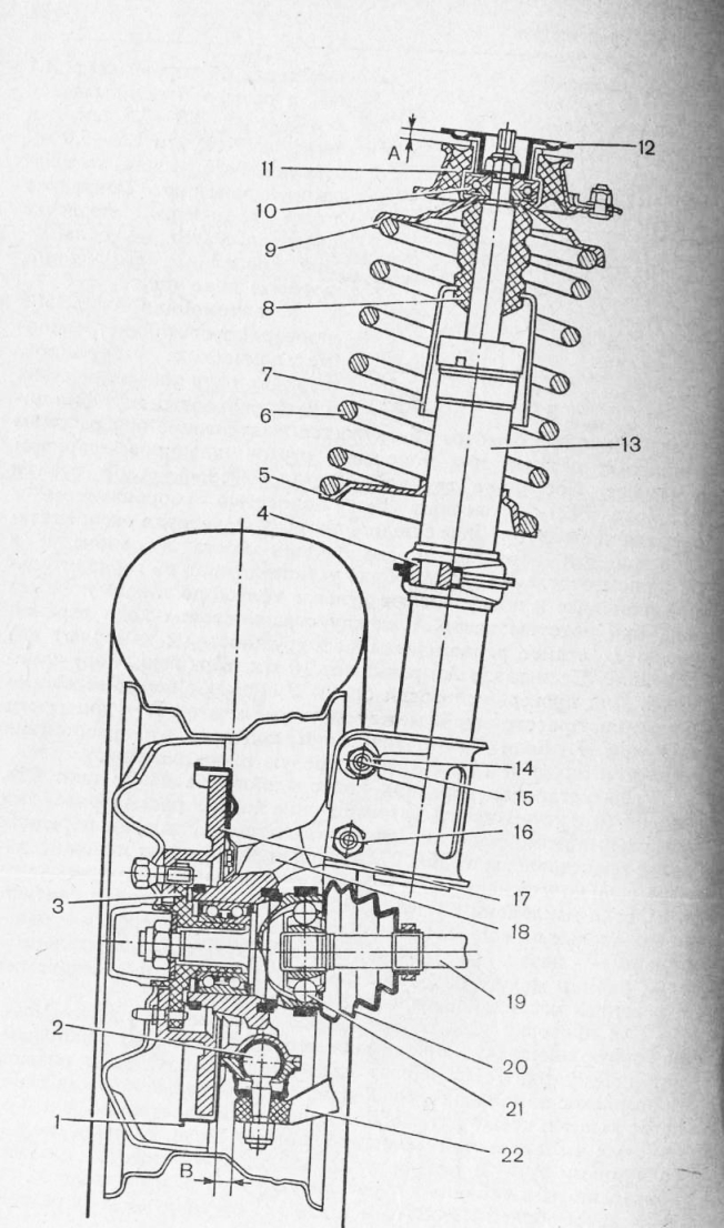
Rice. 25. Front wheel with a telescopic stand of the car VAZ-2109:
Then the car is rolled forward so that the measuring points marked on the rim move back and also stand 180 mm from the surface of the platform and repeat the measurement. If the measurement results do not match the data in Table. 27 carry out the adjustment In cars IZH-2715 and VAZ-2121, the toe-in of the front wheels is adjusted by changing the length of the side rods, and in the car VAZ-2109 by changing the length of the right and left steering rods. In the UAE-31512 car, the toe-in of the front wheels is regulated by changing the length of the lateral steering rod. When adjusting the toe-in of the wheels of a VAZ-2109 car, the plane of the bottom of the outer tip is set parallel to the plane of the supporting surface of the pivot arm.
If the setting of the angles of rotation of the wheels does not match, the vehicle's maneuverability when cornering is impaired or the tires of the front wheel rub against the protruding parts of the front suspension and side members.
For the IZH-2715 car, at the maximum steering angle, the gap between the tire and protruding parts for the left and right wheels should be 10-15 mm. Adjust the angle of maximum rotation of the wheels with a restricting bolt screwed into the bracket on the side members.
For the U AZ-31512 car, the maximum angle of rotation of the right wheel to the right, and the left to the left should not exceed 27 °.
Rice. 26. Checking the parameters of the installation of the front wheels: a - camber angle: 1 - car wing; 2 - a plumb line; b - wheel alignment
For this, a thread is pulled along the upper part of the root sheet. Then measure the distance from the middle of the thread to the middle of the root leaf. For the IZH-2715 car, the rear spring deflection should be equal to 70 mm, and for the UAE-31512 car, this value should be at least 100 mm for the front spring, and 119 mm for the rear one. The difference between the deflection boom for the right and left springs of the same name should not exceed 10 mm. In the case of an IZH-2715 car, springs are added to each additional second sheet in the event of a draft. Check the condition of the anti-squeak gaskets and washers, which are installed at the ends of the second and fifth spring sheets. Replace worn gaskets and washers.
When inspecting shock absorbers and hydraulic struts, they check their tightness, the condition of rubber bushings, rubber-metal hinges, as well as their attachment to the body, frame or suspension of cars. The performance of the shock absorbers and hydraulic struts is checked by swinging the vehicle over the unit under test at the top. Oscillations cease 3-4 periods after the application of force with serviceable shock absorbers or hydraulic struts. In addition, the shock absorbers are checked by pumping them by hand. In this case, the lower ends of the shock absorbers are disconnected. A good shock absorber has more tensile resistance than compression. A defective shock absorber may have dips or seizures during pumping.
The reasons for the malfunction of the shock absorbers include oil leakage through the oil seals, clogged valves, and spring sediment. If faults are found, tighten the gland nut or replace it. Sagging or broken springs and parts are washed and replaced.
To eliminate faults, replace the spring or put lining under its upper end, replace worn parts, repair springs, shock absorbers, check the reliability of fasteners, adjust wheel alignment and convergence, set tire pressure, replace tires and balance wheels, fix suspension faults.
Suspensions of cars are dependent, spring. The front suspension has hydraulic shock absorbers, the rear suspension for GAE -53-12, ZIL -431410, ZIL -4331, KAZ-4540 - additional springs.
Spring suspension malfunctions: breaks and cracks on the leaf springs, loss of elasticity and wear along the thickness of the leaf springs, wear of rubber pads, clamps, breakage of the center bolt, wear of pins, upper and lower supports, earrings. To eliminate faults, the spring is removed, worn and broken parts are replaced, after disassembly, the spring deflection boom is checked. Before assembly, the sheets are lubricated with graphite grease. It is possible to replace worn out pillows with others cut from the old tire.
The performance of the shock absorber is impaired when the valves are clogged or parts are broken. In this case, the shock absorber is disassembled, washed, and worn and broken parts are replaced. Damage to shock absorbers also include rod wear and scuffing on its surface, shrinkage or breakage of valve springs, wear of piston compression rings, fluid leakage through oil seals. Liquid leakage is eliminated by tightening the reservoir nut or replacing the gland. When disassembling the shock absorber and installing the rubber rod seals, their inner surfaces, mating with the rod, are lubricated with CIATIM -201 grease. When assembling, take into account that the compression, recoil and bypass valves cannot be interchanged, as this will disrupt the normal operation of the shock absorber. After installing the valves, the plugs are screwed up and fresh liquid is poured into the body through the filling hole. After assembly and filling the liquid, the shock absorber is checked at the stand.
To change the fluid, the shock absorber is removed from the car, placed vertically and, fixing the lower eyelet, raise the rod to the upper position, unscrew the reservoir nut and remove the rod with the piston. Prepare the required amount of fluid for the shock absorber and fill the working cylinder to the top. The remaining liquid is drained into the shock absorber reservoir, then the shock absorber is assembled in reverse order and installed on the vehicle. Shock absorbers do not require special adjustment during operation, and their malfunction is indicated by prolonged rocking of the car while driving.
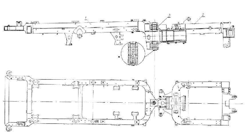
Rice. 27. Rear suspension of the KAMAE-5320 car: 1 - rear spring buffer; 2 - spring; 3 - jet rod bracket; 4 - rod 9, 16 - pins; 10 - expanding sleeve; 11 - spring support; 12 - rear axle; 14 - poppy; 19 - spring shoe; 20 - shoe cover gasket; 21 - nut; 22 - filler cuff; 27 - persistent ring; 28 - stuffing box; 29 - nut for fastening the brace-bracket of the balancer; 35 - rear suspension bracket; 36 - oiler
When the lining of the sliding end of the root sheet of the rear suspension of the ZIL -431410 car is worn out, the lining is removed. Crackers of the sliding end of the front and rear springs, when worn by more than half the wall thickness, are rearranged so that they rest on the lining of the main sheet with the unworn part. The stepladders of the car springs are tightened in sequence: two front nuts in the direction of the car, and then two rear nuts.
In the KAMAE-5320 car, in the front suspension, to protect the spring bracket wall from wear, liners are installed on the fingers of the crackers and secured with a tie bolt. At the sliding end of the root sheet, a pad is fixed with rivets, which protects the main sheet from wear. In the rear suspension, each leaf spring is attached by means of ladders to the axle shoe of the balancer device. The ends of the springs fit into the holes of the supports welded to the bridge girders. When deflected, the ends of the springs slide into the supports. Pushing forces and reactive moments are transmitted to the frame by six rods. The hinges of the rods are self-moving; to protect them from water and dirt, sealing collars are installed, for lubrication - oiler.
The balancing device has two axles, shoes. The brackets are coupled with a tie and fixed with studs on the brackets of the rear bogie. Self-moving oil seals and O-rings prevent oil from leaking out of the suspension hubs. The oil filler cap has a hole with a plug. If the seals of the shoes of the balancing device and the hinges of the reaction rods are damaged, these assemblies are disassembled, the damaged seals are replaced. If the axles and bushings of the balancing device are worn out, they are ground until the signs of wear are removed and repair bushings are installed. When the ends of the root sheets of the rear springs are worn by half the thickness, the first and third sheets are interchanged. The axial clearance in the shoe of the balancing device is adjusted when the vehicle is raised, the rear spring is removed, or when the ends of the rear spring are released from the axle supports. To do this, screw the shoe fastening nut so that the balancer does not rotate by hand. If it turns, the operation is repeated.
At maintenance the suspensions periodically check the condition of the springs and shock absorbers and eliminate the identified malfunctions.
With TO-1, the springs are cleaned of dirt, the spring fingers are lubricated, the fastenings of the springs, shock absorbers and suspension brackets are checked. Check the tightening of the nuts of the stepladders for attaching the spring lugs, tighten until the spring washers are compressed.
With TO-2, they additionally check the absence of skewing of the front and rear axles, the condition of the frame, suspension, shock absorbers, fasten the stepladder clamps and fingers of the front and rear springs, front spring cushions and shock absorbers.
At the KAMAE-5320 car, they lubricate the fingers of the springs, the hinges of the reaction rods, the shoes of the balancing device, check the fastening of the springs, shock absorbers, the reaction rods and brackets, the serviceability of the sealing cuffs on the shoes of the balancing device and the rods, check and adjust the axial clearances in the shoes of the balancing device, check no clearance in the hinges of the jet rods. Oil is poured into the shoes to the level of the filling holes closed with plugs. To drain the oil, remove the cover from the balancer suspension shoe. Simultaneously with the oil change, the axial clearance in the balancing device shoes is checked. If necessary, tighten the nuts after loosening the tie bolts. After tightening, the shoes should rotate on the axles.
TO Category: - Car maintenance
Rice. 127. Hydraulic shock absorber: I - eyelet; 2 - casing; 3, 4 - oil seals; 5 - bypass valve; 6, 15 - holes in the piston; 7 - recoil valve; 8, 11 - springs; 9 - inlet valve; 10 - compression valve; 12, 13 - holes in the base; 14 - piston; 16 - case; 17 - cylinder; 18 - stock; 19 - hole in the rod guide.
The main parts of the shock absorber (Fig. 127) are the housing 16, the working cylinder 17, the casing 2, the piston 14 with the rod 18, the compression valve 10, the recoil valve 7, the bypass valve 5, the inlet valve 9. The working cylinder is located inside the housing, from the bottom to a base is welded to it, and from above the cylinder is closed by a rod guide. Inside the cylinder, a piston moves, connected to the rod. The piston has two rows of circular holes. Openings 6 on a large diameter are closed by a bypass plate valve 5, openings on a smaller diameter 15 are closed from below by a recoil valve plate 7. At the base of the cylinder there is one row of holes around the circumference, which are closed from above by an intake valve 9. In the center of the base there is a compression valve 10.
The space between the cylinder and the piston is called the reserve cavity; together with the working cylinder, it is filled with liquid.
The stem exit from the cylinder is sealed with a rubber gland 3. Between the gland ring and the rod guide, an gland 4 is installed, which seals the reserve cavity.
Shock absorber operation. With a smooth compression stroke, the piston is mixed down, pressure is created under it, due to which the bypass valve 5 on the piston opens, and the liquid flows into the space above the piston. All liquid from under the piston cannot flow into the space above the piston, since part of the volume above the piston is occupied by the rod. Therefore, part of the liquid through the slightly opening compression valve 10 flows into the reserve cavity.
With a sharp compression under the piston, a great pressure, the compression valve opens a large amount. The liquid flows through valve 5 into the space above the piston and through valve 10 into the reserve cavity.
With a smooth recoil stroke, pressure is created in the space above the piston. The liquid flows through holes 15 and slots in the recoil valve 7 into the space under the piston. At the same time, liquid from the reserve cavity enters the same space through the inlet valve 9.
With a sharp recoil stroke, the pressure above the piston rises rapidly. The liquid, overcoming the force of the spring, opens the valve 7 and flows into the space under the piston. At the same time, part of the liquid from the reserve cavity passes through the inlet valve 9 into the space under the piston.
In all cases, when the liquid flows through the narrow valve openings, friction of the liquid against the walls of the openings and between its layers is created. This friction dampens frame vibrations. Heat is generated during friction, so a properly functioning shock absorber must be warm.
Rice. 128 Rear suspension of a three-axle vehicle: 1 - intermediate bridge; 2, 3 - rocket rods brackets; 4, 8 - spring brackets; 5 - spring; 6.15 - suspension bracket; 7 - stepladder; 9 - rear axle; 10, 11, 14-jet rods; 12 - balancer; 13 - axis.
Rear suspension (fig. 128) three-axle vehicles dependent, spring, balancing. The main parts of such a suspension are two inverted springs 5, two balancers, two axles 13 (on Ural-4320 and ZIL-131 cars - one common axle), two axle brackets, two rear suspension brackets, six jet rods 10, 11, 14 , four rubber buffers.
Axle 13 is pressed into bracket 6, which is fixed with studs to bracket 15, the latter is bolted to the frame side member. At the ends of the axles 13, on two bushings each, balancers 12 are installed. From axial displacements, the balancer is fixed with a split nut tightened with a bolt. The rubbing surfaces of the balancer are lubricated with oil poured through the upper hole in the balancer cover, the oil is drained through the lower hole, the holes are closed with plugs. From the side of the bracket b, the balancer is sealed with an oil seal and rubber rings.
The spring in the middle part is attached to the balancer with two ladders 7. The ends of the springs are installed freely in the brackets of the bridge beams.
Rubber bumpers attached to the frame side members restrict the upward travel of the axles and soften the impact of the frame beams.
Reactive rods are used to transfer pushing and braking forces from the axle beams to the frame, they also perceive reactive moments from the bridges that arise when starting off or braking. Each bridge has three rods - one upper and two lower. The rod consists of a rod and two heads. On KamAZ-4310 and Ural-4320 vehicles, ball pins with inserts and a spring are installed in the rod heads, the head is closed with a lid. There is a grease nipple in the head to lubricate the rubbing surfaces of the hinge. On the ZIL-131 car, a ball pin and a holder with inserts are installed in the head. The liner is made of woven tape impregnated with a special compound. The hinge is sealed with a rubber boot. During operation, the hinges of the jet rods on this car do not require lubrication.
The jet rods are attached to the suspension brackets and axle arms.
With a balanced suspension, both axles form a common bogie, which can swing together with the springs on the axle and, in addition, due to the deflection of the springs, each axle can move independently, which ensures good adaptability of the wheels to uneven road surfaces.


