_____________________________________________________________________
Steering components Lada Granta, Kalina
Steering Lada Kalina / Granta VAZ-2190 cars with electric booster and tilt-adjustable steering column.
The steering wheel is mounted on the steering shaft splines and secured with a self-locking nut. On cars equipped with a driver's airbag instead of a lining in wheel the airbag module is installed.
The steering shaft is composite. It consists of an upper shaft and a countershaft. The upper shaft rotates in two bearings pressed into the steering column tube.
An ignition lock with an anti-theft device is installed on the upper part of the column pipe. The intermediate shaft is collapsible, has two cardan joints at the ends.
The steering column of the Lada Granta / Kalina is assembled with a geared motor and an electric power steering control unit. The efficiency of the electric booster depends on the speed of the vehicle.
The electric booster works only when the engine is running. The steering column brackets are attached to the body on four studs with self-locking nuts. The brackets are pivotally connected to the steering column tube.
The upper bracket is equipped with a steering column locking mechanism. By moving the locking lever to the lower position, you can change the angle of the steering column. When the lever is raised, the speaker locks in the selected position.
The steering gear Lada Kalina / Granta VAZ-2190 is a rack-and-pinion type, consists of a crankcase, a drive gear and a rack, which are in gearing. The mechanism is fixed to the bulkhead of the engine compartment with two brackets on rubber mounts.
When the steering wheel is turned, the rotation is transmitted through the upper and intermediate shafts of the steering column to the drive gear, which, turning, mixes the rack.
Bolted to the Lada Granta / Kalina steering rack steering rods, which consist of the actual rods, tips and adjusting sleeves. At the inner ends of the steering rods, there are lugs with rubber-metal bushings pressed into them.
Ball pins are installed in the outer ends of the rods, with which the steering rods are connected to the pivot arms of the front suspension struts. When moving the rack, the rods turn the front suspension struts.
The length of the steering rods can be changed by rotating the adjusting sleeves and thereby changing the toe-in of the front wheels. The bushings are secured from spontaneous rotation with tie bolts wrapped in the flanges of the steering rod ends.
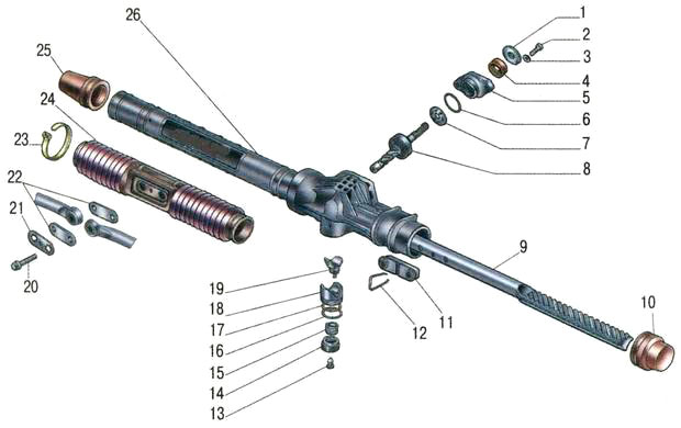
Fig. 32. Steering Lada Granta / Kalina
1 - tie rod tip; 2 - an adjusting sleeve; 3, 6 - steering gear mounting brackets; 4, 5 steering rods; 7 right protective cap; 8 - right support of the steering mechanism; 9 - protective cover of the steering mechanism; 10 - steering gear; 11 - sealant; 12 - intermediate shaft with a lower cardan joint; 13 - top cardan joint; 14 - steering column with electric power steering; 15 - steering wheel; 16 - contact ring; 17 - steering wheel mounting nut; 18 - steering wheel pad (driver's airbag); 19 steering bearings
shaft; 20 left protective cap; 21 left steering gear support
Checking the steering Lada Granta / Kalina
We visually check the condition of the protective covers of the ends of the steering rods and the steering mechanism. Damaged covers (torn, cracked) must be replaced.
Make sure that the steering column lock lever is raised to the stop. Trying to move the steering wheel in a vertical plane, we check the reliability of the steering column attachment by the locking mechanism.
If steering column Lada Kalina / Granta VAZ-2190 moves, remove the steering column linings and tighten the nut of the steering column lock lever axis with a 13 mm wrench.
Trying to move the steering wheel along the axis of the steering shaft, we make sure that there is no steering wheel play on the splines of the shaft and shaft in the steering column.
To check the steering play, turn the steering wheel to the straight ahead position. We put a slotted screwdriver on the dashboard so that its blade is located next to the steering wheel rim (for reliability, it can be fixed with masking tape).
Turning the steering wheel to the right before the wheels start turning (choosing the backlash), and then to the left and guiding ourselves by the blade of a screwdriver, with chalk, pieces of wires or otherwise, mark these positions on the rim. Backlash should not exceed 5 "(or 18 mm) when measured from the outside of the rim.
Increased backlash indicates the need for troubleshooting. As a rule, first of all, in the steering of the Lada Granta / Kalina, the tips of the steering rods fail.
To check that there is no play in the ends of the steering rods, the assistant slightly shakes the steering wheel from side to side. We put our hand at the junction of the tie rod with the pivot arm of the suspension strut so that the palm touches them at the same time.
When a backlash appears in the tie rod tip, the pivot arm will feel displaced relative to the tie rod. We check the tightening of the nuts of the steering column universal joint bolts. We repeat the check on the other side of the car. Defective hinges are replaced.
When swinging the steering wheel from side to side, listen to the operation of the steering mechanism. A knock on the right side of the steering box indicates wear on the bearing bush. The defective steering gear is removed and repaired or replaced.
We turn on the ignition - on the instrument panel, the control lamp for the malfunction of the electric power steering should light up. We start the engine.
The control lamp should go out, the steering wheel should turn easily with one hand. If the lamp comes on while the engine is running, it indicates a malfunction of the electric amplifier and the need to repair it.
Replacing the steering column Lada Kalina / Granta VAZ-2190
Depending on the purpose of the operation, the steering column can be removed as an assembly with the steering wheel and steering column switches. The operation is described with a partial disassembly of the steering column.
We turn the steering wheel to the position corresponding to the movement in a straight line. Removing the steering wheel
We remove the decorative lining of the steering column.
Use a Phillips screwdriver to unscrew the three self-tapping screws and remove the lower trim of the instrument panel.
Disconnect the wiring harness pads from the steering column switches and slip ring.
We loosen the tie bolt and remove the connector assembly with the steering column switches and the slip ring.
Disconnect the ignition switch wiring harness pads.
Releasing the latches, disconnect the two pads of the wiring harness from the electric power steering Lada Granta / Kalina.
The steering column can be removed as an assembly with an intermediate shaft. However, it is more convenient to remove and install the steering column if you disconnect the intermediate shaft.
The connection of the flanges of the cardan joints of the intermediate shaft is possible only in one position, therefore, their relative position can not be marked.
We unscrew the nut of the tie bolt connecting the cardan joints of the intermediate shaft. We remove the bolt.
We loosen the tightening of the two nuts of the lower fastening of the steering column Lada Granta / Kalina.
With the same key, unscrew the two nuts of the upper mounting of the steering column.
Remove the steering column assembly.
We unscrew the nut of the clamping bolt of the flange of the lower propeller joint of the intermediate shaft. We remove the bolt.
Using a slotted screwdriver, unclench the flange and remove the cardan joint from the splines of the shaft of the steering rack mechanism Lada Kalina / Granta VAZ-2190.
Mark the relative position of the flange of the upper universal joint and the steering shaft with a marker or other available method. Using a 13 mm socket wrench, unscrew the nut of the tightening bolt, holding the head of the bolt with a spanner of the same size.
Through the beard we knock down the cardan joint from the slots.
Install the steering column in reverse order.
Before installing, make sure that the front wheels are in a straight-ahead position, and that the groove on the shaft and the mark on the steering box housing cover, as well as the marks on the protective cover are positioned properly.
Tighten the nuts of the tie bolts on the intermediate shaft flanges with a torque of 23 - 28 Nm (2.3-2.8 kg / cm). Tighten the steering column mounting nuts with a torque of 15-18.6 Nm (1.5-1.9 kg / cm).
Replacing the steering rack mechanism Lada Granta / Kalina
Disconnect the tie rod ends from the front suspension struts.
To prevent damage to the slip ring on vehicles with an airbag in the steering column, secure the steering shaft against rotation.
Disconnect the intermediate shaft of the steering column from the shaft of the steering gear.
We unscrew the four nuts and remove the two brackets of the right mounting of the steering rack Lada Kalina / Granta VAZ-2190 to the bulkhead of the engine compartment.
We slightly move the steering gear forward and remove the drive gear shaft from the hole in the bulkhead of the engine compartment.
Turning the steering gear with the shaft upwards, we remove it from the engine compartment through the opening in the left mudguard.
Install the steering gear in reverse order.
We connect the intermediate shaft of the steering column to the shaft of the steering rack mechanism.
Replacing the steering rod Lada Granta / Kalina
Remove the front left wheel.
Press out the outer rod end finger from the hole steering knuckle.
Using a slotted screwdriver, remove the locking plate of the bolts for attaching the steering rods to the steering gear.
We loosen the tightening of the bolt securing the right rod and unscrew the bolt that secures the left rod to the steering gear.
We take out the bolt securing the left steering rod Lada Kalina / Granta VAZ-2190 and turn the bolt plates down.
We take out the left rod through the hole in the mudguard.
We measure the length of the removed thrust (the distance between the center of the hole of the rubber-metal sleeve of the inner end of the thrust and the center of the plug of the ball pin hole).
We loosen the tightening bolt new thrust... Turning the adjusting sleeve with a wrench 27 mm, we make the length of the new rod equal to the length of the removed rod.
Install traction in reverse order.
Tighten the thrust bolt with a torque of 19-30.9 Nm (2.0-3.2 kg / cm).
We tighten and cotter the bolt for fastening the rod ends to a torque of 27.1 - 33.4 Nm (2.8 - 3.4 kg / cm).
Tighten the bolts of the rods to the steering gear with a torque of 70-86 Nm (7.1 - 8.6 kg / cm) after installing the car on the wheels.
We put the locking plate on the bolts.
Replacing the tip of the tie rod Lada Granta / Kalina
We shoot front wheel from the side of the replacement tip.
We clean with a metal brush threaded connections tips from dirt and treat them with a penetrating grease.
Using the pliers, we straighten and remove the cotter pin from the hole in the ball pin of the rod.
We turn off the castellated finger nut.
Using a puller, we press out the finger from the hole in the steering knuckle of the front suspension strut.
We loosen the tightening bolt of the tie rod end Lada Kalina / Granta VAZ-2190.
Use a slotted screwdriver to open the tip flange.
Rotating the outer tip and counting number of revolutions, screw the tip off the rod (if the adjusting sleeve begins to rotate with the tip, hold it with a 27 mm open-end wrench).
The number of revolutions made is counted in order to approximately set the toe-in of the wheels during assembly.
We cover the threaded part of the new tip with Litol grease or similar.
We screw the new tip onto the adjusting sleeve, holding it with a 27 mm open-end wrench.
We insert a finger into the hole of the pivot arm of the rack and wrap the castellated nut.
We tighten the finger nut to a torque of 27.1 - 33.4 Nm (2.83.4 kg / cm) and turn it until the hole in the finger aligns with the nearest slot in the nut.
We cotter the nut (insert the cotter pin into the finger and spread the ends of the cotter pin in different directions).
Tighten the handpiece flange clamping bolt 19.1 -30.9 Nm (2.0-3.2 kg / cm).
Reference data
Basic data for monitoring, regulation and maintenance
Table 11.1
Tightening torques for screw connections
Table 11.2
|
Name of assemblies and parts |
Tightening torque, Nm (kgf-m) |
|
|
Steering rack nut |
15-18,6 (1,5-1,9) |
|
|
Steering column nut |
15-18,6 (1,5-1,9) |
|
|
Nuts of the tie bolts of the intermediate shaft flanges |
23-27,4 (2,3-2,8) |
|
|
Tie rod pinch bolt |
19-30,9 (2,0-3,2) |
|
|
Steering wheel nut |
31,4-51 (3,2-5,2) |
|
|
Tie rod bolt retaining nut |
27,1-33,4 (2,8-3,4) |
|
|
Bolt of fastening of the steering rod to the steering gear |
||
|
Steering Gear Bearing Nut |
Description of the structure
Electric power steering with tilt-adjustable steering column.
The steering wheel is mounted on the steering shaft splines and secured with a self-locking nut. On vehicles equipped with a driver's airbag, an airbag module is installed instead of a steering wheel pad.
The steering shaft is composite. It consists of an upper shaft and a countershaft. The upper shaft rotates in two bearings pressed into the steering column tube. An ignition lock with an anti-theft device is installed on the upper part of the column pipe. The intermediate shaft is collapsible, has two cardan joints at the ends.
The steering column is assembled with a geared motor and an electric power steering control unit. The efficiency of the electric booster depends on the speed of the vehicle. The electric booster works only when the engine is running. The steering column brackets are attached to the body on four studs with self-locking nuts. The brackets are pivotally connected to the steering column tube. The upper bracket is equipped with a steering column locking mechanism. By moving the locking lever to the lower position, you can change the angle of the steering column. When the lever is raised, the speaker locks in the selected position.
The rack-and-pinion steering mechanism consists of a crankcase, a drive gear and a rack, which are in gear engagement. The mechanism is fixed to the bulkhead of the engine compartment with two brackets on rubber mounts. When the steering wheel is turned, the rotation is transmitted through the upper and intermediate shafts of the steering column to the drive gear, which, turning, moves the rack.
The steering rods are bolted to the steering rack, which consist of the actual rods, tips and adjusting bushings. At the inner ends of the steering rods, there are lugs with rubber-metal bushings pressed into them. Ball pins are installed in the outer ends of the rods, with which the steering rods are connected to the pivot arms of the front suspension struts. When moving the rack, the rods turn the front suspension struts. The length of the steering rods can be changed by rotating the adjusting sleeves and thereby changing the toe-in of the front wheels. The bushings are secured from spontaneous rotation with tie bolts wrapped in the flanges of the steering rod ends.
Basic data for monitoring, regulation and maintenance
Tightening torques for screw connections
Electric power steering with tilt-adjustable steering column.
The steering wheel is mounted on the steering shaft splines and secured with a self-locking nut. On cars equipped with a driver's airbag, instead of a lining in the steering wheel, an airbag module is installed.
The steering shaft is composite. It consists of an upper shaft and a countershaft. The upper shaft rotates in two bearings pressed into the steering column tube. An ignition lock with an anti-theft device is installed on the upper part of the column pipe. The intermediate shaft is collapsible, has two cardan joints at the ends.
The steering column is assembled with a geared motor and an electric power steering control unit. The efficiency of the electric booster depends on the speed of the vehicle. The electric booster works only when the engine is running. The steering column brackets are attached to the body on four studs with self-locking nuts. The brackets are pivotally connected to the steering column tube. The upper bracket is equipped with a steering column locking mechanism. By moving the locking lever to the lower position, you can change the angle of the steering column. When the lever is raised, the speaker locks in the selected position.
The rack-and-pinion steering mechanism consists of a crankcase, a drive gear and a rack, which are in gear engagement. The mechanism is fixed to the bulkhead of the engine compartment with two brackets on rubber mounts. When the steering wheel is turned, the rotation is transmitted through the upper and intermediate shafts of the steering column to the drive gear, which, turning, mixes the rack.
The steering rods are bolted to the steering rack, which consist of the actual rods, tips and adjusting bushings. On the inner ends of the steering rods, lugs are made with rubber-metal bushings pressed into them. Ball pins are installed in the outer ends of the rods, with which the steering rods are connected to the pivot arms of the front suspension struts. When moving the rack, the rods turn the front suspension struts. The length of the steering rods can be changed by rotating the adjusting sleeves and thereby changing the toe-in of the front wheels. The bushings are secured from spontaneous rotation with tie bolts wrapped in the flanges of the steering rod ends.
Steering: 1 - tie rod tip; 2 - an adjusting sleeve; 3, 6 - steering gear mounting brackets; 4, 5 steering rods; 7 right protective cap; 8 - right support of the steering mechanism; 9 protective cover of the steering gear; 10 - steering gear; 11 - sealant; 12 - intermediate shaft with a lower cardan joint; 13 - upper cardan joint; 14 - steering column with electric power steering; 15 - steering wheel; 16 - contact ring; 17 - steering wheel mounting nut; 18 - steering wheel pad (driver's airbag *); 19 steering shaft bearings; 20 left protective cap; 21 left steering gear support
Complexity
Not indicatedNot indicated
Instruments:
Parts and consumables:
- Oil filter
- Engine oil
- Rags
Notes:
It is necessary to regularly check the condition of the steering, because it is on it that driving safety depends.
At every maintenance check the condition of the steering boot 7 (see "Diagram of the steering VAZ Lada Kalina 1118"), boot 27 steering rod joints and their tightness. Anthers must be replaced in the presence of cracks, ruptures and other defects that violate the tightness, otherwise water, dirt and dust trapped in the nodes will quickly disable them.

Steering diagram of the VAZ Lada Kalina 1118:
1 - inner tips of steering rods;
2 - bracket for fastening the steering mechanism;
3 - nut of the steering rod hinge;
4 - outer tip of the tie rod;
5 - adjusting rod;
6 - support of the steering mechanism;
7 - steering gear;
8 - bracket for mounting the steering mechanism;
9 - nut of the bolt of fastening of the steering shaft and the drive gear of the steering mechanism;
10 - washer;
11 - cardan shaft with a hinge;
12 - tie bolt;
13 - electronic control unit for the electric booster;
14 - nut for fastening the steering column;
15 - egnition lock;
16 - upper facing casing of the rudder shaft;
17 - electric power steering;
18 - nut for fastening the steering wheel;
19 - signal switch;
20 - wheel;
21 - sealing ring;
22 - steering column adjustment lever;
23 - fastening screw;
24 - the lower casing of the rudder shaft;
25 - sealant;
26 - spring ring;
27 - anther;
28 - sealing ring.
Make sure that when the steering wheel and the vehicle wheels are in a straight line, the steering wheel spoke is horizontal. Otherwise, determine the cause of the malfunction and eliminate it.
While turning the steering wheel from lock to lock, visually and audibly check the following:
— operation of the steering column adjustment mechanism. When the adjustment lever is lowered, the steering column should move up and down smoothly, without jerking or jamming, and when the lever is raised, it should be securely fixed in the installed position.

— lack of clearance in silent blocks (rubber-metal hinges), steering rod hinges, riveted and splined joints of the elastic coupling of the steering shaft;
— secure tightening of bolts 20 (see "The steering gear of the car Lada Kalina VAZ 1118") and stopping them with a plate 21 fastening the rods to the rail and the nuts of the hinge fingers of the outer ends 4 (see "Steering diagram of the car Lada Kalina VAZ 1118") steering rods;
— if there are any sticking or knocking sounds in the steering wheel that prevent the steering wheel from turning.
— condition of the right and left protective caps of the steering gear. The damaged cap must be replaced with a new one.
If knocks and sticks are found in the steering, disconnect the tie rods from the pivot arms of the telescopic suspension struts and recheck. After making sure that knocks and jams come from the steering, remove the steering from the vehicle, check the gap between the steering rack stop and the nut. If necessary, replace the worn steering parts and adjust the clearance between the stop and the nut. If the jamming and knocking have not stopped, the steering gear must be removed from the car and replaced.
Helpful advice:
Repair of the steering mechanism of the VAZ Lada Kalina 1118 is recommended to be carried out in a specialized center.
To check the backlash in the steering, set the front wheels and steering wheel to the position corresponding to the straight-line movement of the car.

Turn the steering wheel in both directions until the wheels start turning (while the wheels must remain stationary). The total backlash of the steering wheel of the VAZ Lada Kalina 1118 should not exceed 5 °(corresponds to turning the steering wheel by 15 mm), provided that the steering mechanism, steering rods, front wheel hub bearings and telescopic struts are in good working order. If necessary, replace the defective parts and tighten the loosened fasteners of the steering elements. The presence of knocking and backlash in the rubber-metal joints of the steering rods and the ball joints at the ends of the rods is not allowed.
The steering gear of the car Lada Kalina VAZ 1118:
1 - anther;
2 - bolt;
3 - washer;
4 - stuffing box;
5 - crankcase cover;
6 - sealing ring;
7 - assembled separator;
8 - drive gear with bearing assembly;
9 - steering rack;
10 - left protective cap;
11 - thrust support;
12 - bracket;
13 - plug;
14 - stop nut;
15 - stop spring;
16 - retaining ring;
17 - sealing ring;
18 - rail stop;
19 - stop insert;
20 - bolt;
21 - locking plate;
22 - cover plate;
23 - clamp;
24 - anther;
25 - right protective cap;
26 - steering gear housing.