In the mechanisms of machine tools, belt, chain, gear, screw, rack and pinion drives, couplings, etc. are used to transfer motion from one link to another. Symbols mechanical transmissions and other elements in the drives of machine tools are given in table. 5.
The belt drive consists of two pulleys mounted on two shafts and interconnected by a flexible belt. One pulley is called the leading pulley, the second pulley receives rotation from the first as a result of frictional forces between the belt and the pulleys and is driven. Depending on the cross-sectional shape of the transmission belt, there are wedge, flat and round belts. The belts also serve for the direct transmission of rotation from the electric motor to the machine spindle, when it is required to report high rotational speeds and smooth vibration-free operation of the machine must be achieved (in high-speed lathes and on grinding machines etc.). In the mechanisms of auxiliary movements, in addition to V-belts, transmissions by a flat belt, transmissions by a round belt and a cord are used.
In V-belt transmission(Fig. 32, a) the rubberized belt has a trapezoidal profile, and the pulley has corresponding annular grooves. V-ribbed belts (Fig. 32, b) have several longitudinal V-ribs on the inner side. The load in such gears is distributed evenly over the width of the pulley. V-ribbed belts provide, in comparison with V-belts, greater constancy of the gear ratio, less vibrations and allow the use of pulleys with smaller diameters. For greater flexibility, especially when working at high speeds and small diameters of pulleys, V-belts are used with teeth located across the belt, and sometimes on its outer parts (Fig. 32, c, d). 
In gear transmission, where the belt and the pulley are toothed, there is no slippage, the belt does not stretch and has high strength due to the main bearing element (metal or synthetic cable, which is molded with rubber). 
The gear ratio of the belt drive is defined as the ratio of the rotational speed n 2 of the driven shaft to the rotational speed n 1 of the drive shaft: 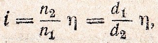
where d 1 is the diameter of the drive pulley, mm; d 2 - the diameter of the driven pulley, mm; ƞ - coefficient of adhesion, taking into account belt slippage (usually ƞ ≈ 0.985).
For stepped transmission control, stepped pulleys are used, fixed on shafts I and II (Fig. 32, e). Gear shifting is carried out by shifting the belt from one stage to another. The sum of the diameters of the mating pulleys is made constant at all stages, that is, d 1 + d 2 = d 3 + d 4.
Comparing flat and V-belt transmissions, it should be noted that V-belt transmissions have advantages: there is no belt stitching, which serves as a source of vibration; the presence of lower forces acting on shafts and bearings.
These advantages led to the replacement of flat-belt transmissions with V-belts. For high-speed gears operating at speeds up to 75 m / s, belts made of synthetic materials are used.
Chain transmissions, according to the nature of the work performed, are divided into drive, cargo, traction. Unlike belt belts, they have no slippage and can reliably transmit high torque at different gear ratios. Chain drives are used to a limited extent in the drives of the main movement. They can operate at high speeds (up to 30 m / s) at both small and large center-to-center distances. Drive chains can connect and drive several shafts at the same time. Efficiency of chain drives ƞ = 0.87 ÷ 0.98.
In machine tool mechanisms, gear drives are mainly used to transfer motion between shafts in a wide range of rotational speeds and torques. Compared to belt drives, gear drives are difficult to manufacture and less smooth in operation, resulting in noise. The types of gears used on the machines are shown in Fig. 33. By type gear wheels distinguish between cylindrical, bevel, screw and worm gears; in the direction of the tooth, spur, helical and chevron. According to the number of stages, transmissions are divided into single-stage and multi-stage. Moreover, they can have constant (gearboxes) and variable steps (gearboxes) gear ratios. By the nature of the relative motion of the gears, gears with fixed and movable axes of rotation are distinguished (the latter include planetary and differential gears); by the type of engagement - gears with external, internal and rack and pinion gearing. By appointment (gear) transmissions are divided into non-counting and counting (high-speed, power and general-purpose transmissions).
Power transmissions require durability, strength, ease and smoothness of rotation, quiet operation (for high-speed gears). Increased requirements are imposed on the counting gears: kinematic accuracy, smooth operation of the gear, the amount of backlash, the degree of contact of the teeth, and wear resistance. In fig. 33, a shows a spur gear with spur gears. Depending on the operating conditions, the gear wheels can be rigidly fixed on the shafts or can be movable. A gear train with helical spur gears (Fig. 33, b) provides smoother operation: these gears, unlike spur gears, do not allow axial movement. A gear with chevron gears (Fig. 33, c) is used to transmit large torques, chevron gears exclude axial loads on the shaft supports.
In fig. 33, d shows a transmission of cylindrical gears with a helical tooth and crossed axes; in fig. 33, d - transmission with bevel spur gears, used to transfer rotation between shafts with intersecting axes in Fig. 33, f, g - k onic gears with curved teeth (as opposed to straight-toothed, they provide smoother operation, less noise and greater efficiency and therefore are used for high-speed transmissions). In fig. 33, h shows the transmission with internal engagement.
Cogwheels for critical gear drives of machine tools are made of structural carbon and alloy steels and heat-treated.
For lightly loaded, low-speed and shockless gears, gears are made of gray cast iron. For fast gears nice results(for noiselessness and durability) give polymer materials.
The maximum permissible number of teeth z of the gears is selected taking into account the cutting of the tooth stem, as well as the required smoothness of rotation. For gears in drives of the main movement with uncorrected engagement and an engagement angle α = 20 °, z MIN = 18 ÷ 20 is allowed. In gears where smoothness of rotation is not significant (for example, in control mechanisms), z = 14 is taken rack gears z MIN = 10 ÷ 12.
Worm gears with a cylindrical worm (Fig. 33, i) are used in machine tools for a significant reduction (deceleration) of the rotational speed in feed drives, for auxiliary movements and, in rare cases, for direct transmission of rotation to a spindle, for example, in dividing heads. The main advantages of worm gears:
- the possibility of a significant reduction in the speed of rotation;
- smoothness of rotation;
- the ability to have a retarding effect on vibrations in the kinematic chain, where there is a worm gear.
This property is of particular importance for feed mechanisms, where in the case of insufficient rigidity of the mechanism, the phenomena of abrupt feed of the support or table are observed.
The main disadvantage of worm gears- comparatively low efficiency and, as a result, high heat emission. The smallest permissible number of teeth of worm wheels in feed mechanisms are taken: with single-thread worms 17-18; with two-way 26-28. For critical power transmissions, the optimal number of teeth is 50-70.
The number of worm calls is selected based on the required gear ratio, taking into account the efficiency. The choice of material for the worm gear depends on the sliding speed and the dimensions of the gear. The worm is most often made of steel, heat-treated, a gear worm wheel for sliding speeds up to 2-2.5 m / s - from cast iron; up to 3 m / s - from antifriction alloys, for example, aluminum bronze BrAZh 9-4; over 3 m / s - from tin bronze. It is recommended to polish the worms, as this increases the efficiency of the transmission.
Worm gear ratio:
where z is the number of teeth of the worm wheel; k is the number of worm hits. 
Differential gear mechanisms are a kind of planetary mechanisms. The differential has two degrees of freedom (mobility) and is used to add rotations from two independent sources to one driven link, as well as to split one rotational motion into two, for example, to transfer motion from one engine to two consumers. D The differential consisting of satellites z 2 and z 3, central wheels z 1 and z 4 and carrier 3 is shown in Fig. 34. The gear z 1 rotates about the main speed transmitted by the input shaft 1, the gear z 4 rotates with an additional speed transmitted by the shaft 2, the worm K and the worm wheel z 5. The gear ratio of the differential is determined by the Willis formula:
where n 1, n B, n 4 - the frequency of rotation, respectively, of the input shaft, carrier and gear wheel 4, rpm.
The minus sign means that the wheels z 1 and z 4 rotate in different directions, and the plus sign - in the same direction.
whence the speed of rotation of the carrier 3:
If the gear wheel z 4 is stationary, that is, when there is no additional rotation of the shaft 2, then n 4 = 0 and n B = n 1/2.
Belt drive refers to gears
friction with flexible connection and serves for
rotary motion conversion
using pulleys and drive belt
covering the pulleys.
Driving pulley by frictional forces,
arising on the contact surface
pulley with a belt due to its tension,
sets the belt in motion. Belt in
turn makes it spin
driven pulley. Thus, the power
transmitted from the driving pulley to the driven one.
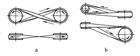
Types of belt drives
a - open transmission;b - cross
broadcast;
c - semi-crossed
transfer (from
interbreeding
shafts);
g - angular gear (with
guiding
roller);
d - transfer from
pressure roller;
e - transfer from
stepped pulley
Belt drive classification by cross-sectional shape
- flat belt(fig. a);
- V-belt
(fig. b);
- round-belted
(fig. c);
- with toothed
belts (fig. e);
- with poly-V
belts (fig. d).
Classification
In the direction of rotation of the pulley:with the same direction
(open and semi-open)
(Fig. 1 a);
- with opposite
directions (cross)
(Fig. 1 b).
By the method of creating tension
belt:
- simple (Fig. 1a);
- with a tension roller (Fig. 1 e);
- with a tensioner (see fig. 2).
Fig. 2. Belt tension adjustment
by moving the engine: 1 - belt; 2
- pulley; 3 - tensioner
By the construction of the pulleys:
- with single-row pulleys (fig. 1,
hell);
- with stepped pulleys (Fig. 1,
e).
Application area.
Belt drives are used to drive units fromelectric motors of low and medium power; for drive from low-power
engines internal combustion... Most widespread in
mechanical engineering find V-belt transmissions (in machine tools,
motor vehicles, etc.). These transmissions are widely used for
small center distances and vertical axes of the pulleys, as well as with
transmission of rotation by several pulleys.
If necessary, provide a belt drive of constant
gear ratio and good traction capacity are recommended
install timing belts.
Flat belts have a rectangular cross-section are used in machines,
which must be resistant to vibration (for example, high-precision
machines). Flat belt transmissions are currently used
relatively rarely (they are replaced by V-belts). In theory
the traction capacity of the V-belt at the same tension force is 3 times
more than flat.
Round-belt transmissions (like power transmissions) are not used in mechanical engineering.
They are used mainly for low-power devices in instrumentation and
household mechanisms (magniophones, sewing machines etc.).
Advantages:
- the possibility of placing the leading and driven pulleys onlong distances (more than 15 meters) (which is important, for example,
for agricultural engineering);
- smooth running, quiet operation of the transmission,
due to the elasticity of the belt;
- low sensitivity to shocks and impacts, as well as
overloads, the ability to slip;
- the ability to work with high angular velocities;
- protection of mechanisms from sudden load fluctuations
due to the elasticity of the belt;
- the ability to work with high revs;
- simplicity of design and low cost.
Disadvantages:
- inconsistency of the gear ratio due toslippage of belts;
- gradual elongation of belts, their fragility;
- the need for constant maintenance (installation and tension
belts, their alteration and replacement in case of breakage, etc.);
- relatively large dimensions transfers;
- high loads on shafts and supports due to belt tension;
- danger of oil getting on the belt;
- low durability at high speeds (ranging from
1000 to 5000 h);
- the need for a tensioner.
Flat belt transmission. Construction and basic geometric relationships
Belt drive with parallel,intersecting or crossing axles with
flat drive belt is called
flat belt. In fig. 1 shows options
flat belt transmission. This transfer is simple
design, can work at very high
speeds (up to 100 m / s) and large center-to-center
distances (up to 15 m). Due to the large
elasticity of the belt, it has a relatively
high durability. For flat belt transmissions
it is recommended to take and< 6 (с натяжным роликом
- to 10). Before the advent of V-belt transmission, flat-belt had a predominant
Spread.
Gear designs, with flat belt
- open (see Fig. 1, a) - the simplest, most reliable andeasy-to-use transmission; it is used for
parallel axes;
- cross (see Fig. 1, 6) - used when
the need to rotate the pulleys in opposite
directions and parallel axes. Has an increased
wear of the belt edge. This transmission does not find
widespread use;
- semi-crossed (see Fig. 1, c) - transmission for
crossing axes;
- angular (Fig. 1, d) - recommended for
intersecting axes (mainly at an angle
90 °).
Materials for flat belt transmissions.
General requirements for drive belt materials:wear resistance and strength under cyclic loads;
high coefficient of friction with pulleys; small module
elasticity and bending stiffness.
These conditions are met by high-quality leather and
synthetic materials (rubber), reinforced
fabric belt (GOST 6982-54), polymer (nylon,
polyamide S-6, rubber SKN-40, latex) or metal
cord. Rubberized fabric belts are used (GOST
101-54), laminated grooved belts with rubber interlayers,
layered and spirally wrapped belts. In damp rooms
and aggressive environments use belts with rubber
gaskets.
Pulleys are made of cast iron grades SCH10, SCH15, SCH25, etc.
The pulley of welded structures is made of steel grades St1, St2
etc. For pulleys of lightweight structures use
aluminum alloys, PCBs. Leather belts are made from animal skin (leather is specially tanned). These belts have a high traction capacity,
elasticity and wear resistance, allow for smaller diameters of pulleys.
However, due to the scarcity and high cost, they are currently
rarely used, only for particularly critical structures. The foundation
rubberized belt - durable vulcanized cord
technical cotton fabric in 2-9 layers interconnected
vulcanized rubber. A fabric with a higher modulus of elasticity
than rubber, transfers the bulk of the load. Rubber increases
coefficient of friction, ensures the operation of the belt as a whole and
protects fabric from damage and abrasion during transmission operation.
Due to its strength, elasticity, low sensitivity to moisture and
temperature fluctuations rubberized belts are widespread.
Depending on the variant of laying the fabric base before vulcanization
belts are divided into three types (Fig. 4): A - cut (the fabric is cut to the width
belt), are used most often, belt speed up to 30 m / s; B -
layer-wrapped, used for heavy-duty work with
speeds up to 20 m / s; B - spirally wrapped, used for small
loads and speeds up to 15 m / s, provides increased
wear resistance of edges. Most flexible type A belts, they got
preferential distribution. .
Textile belts (cotton and
woolen) suitable for work in the atmosphere
dusty, saturated with vapors of alkalis, gasoline,
with sharp fluctuations in load, but traction
their ability is relatively low.
Film
belts made of nylon fabric or twill with friction
coating (film). High static and
the fatigue strength of synthetic materials gave
the ability to reduce the thickness of the belt.
Synthetic fabric belts are made from
nylon or nylon fabric. These belts have
low weight and high coefficient of friction.
They are used in drives of high-speed and
super-fast gears (< 100 м/с).Rubberized
belts of all types
make as without
rubber covers
(for normal
working conditions), so
and with plates (for
work in raw
premises as well
in an environment saturated
vapors of acids and
alkalis). Cotton belts are made on
looms of cotton yarn in
several intertwining layers (four to eight) followed by impregnation
azokerite and bitumen. Cotton
belts are less expensive than
rubberized.
Woolen belts are made from woolen
yarn intertwined and stitched
cotton yarn impregnated
composition of drying oil, chalk and iron red lead.
The load capacity of these belts is higher,
than cotton. Find application
in the chemical industry.
Pulley designs.
Pulleys are made of cast iron,steel, welded or prefabricated, cast from
light alloys and plastics. Pulley diameters
determined from the calculation of the belt drive, and
then round to the nearest value from the series
R40 (GOST 17383-73 *). Cast iron pulleys are used
at speeds up to 30 ÷ 45 m / s. Pulleys small
diameters up to 350 mm have solid discs,
large diameter pulleys - hubs
elliptical variable section. Steel
welded pulleys are used at speeds of 60 ÷ 80
m / s. Light alloy pulleys are promising for
high-speed gears up to 100 m / s.
Basic geometrical parameters of belt drives
Angles α1 and α2,the corresponding
arcs along which
touch occurs
belt and rim
pulley, called
angles of girth.
Calculation of geometric parameters.
... Center distancewhere L is the estimated length of the belt; D1 and D2 - diameters
driving and driven pulleys.
For normal flat belt operation
the condition must be met:
while a should be no more than 15 m. 2. Estimated belt length
add another 100-300 mm to the stitching.
3. Diameter of the drive pulley (small), mm
(where
P1 - power) 4. Diameter of the driven pulley
where and - ratio;
- slip coefficient.
With a diameter D> 300 mm, pulleys are made with
four to six knitting needles. For pulleys with
deviations from standard sizes, produce
strength calculation. Rim count on
strength as a freely rotating ring under
the action of inertial forces; knitting needles count on
bend. Permissible angles of girth of belt drives. Due to the extraction and
sagging of the belt during operation, the wrap angles are measured
approximately:
(6)
In formula (6), the expression
(7)
where β is the angle between the branches of the belt (for
flat belt transmission (β< 30°)). Угол β между
branches of the belt affects the value of the angles of wrap (α1 and
α2). It is also recommended to take the value
diameters of pulleys (D1 and D2), so that
condition
(8)
where for flat belt transmission [α] = 150 °, for
V-belt [α] - = 120 °. Ratio.
In a belt drive, as in a friction drive, as a result
elastic belt slip peripheral speeds are not the same.
Hence the gear ratio
where, ω1 and n1 are the angular velocity and rotational speed of the driving
pulley; , ω2 and n2 - the same, driven pulley; , D1, D2- diameters
driving and driven pulleys; ε - slip coefficient.
The relative speed loss on the pulleys is characterized by
slip coefficient; at an insignificant value
this coefficient (ε< 0,02) приближенно имеем (10)
Efficiency of belt drives. Taking into account the losses during operation, the efficiency
transfers are determined from the expression
where у are the relative losses associated with sliding on
pulleys and due to the elasticity of the belt; Ψnn- relative
support losses; Ψsv- relative losses from resistance
air (taken into account only for large pulleys with spokes).
If the known power on the drive pulley and the power on
slave (reduced due to losses), then the transmission efficiency
for flat-belt open transmission average value
Efficiency 0.96-0.98; for V-belt transmission 0.95-0.96; for
gears with a tension roller 0.95.
Gear classification. Depending on the shape of the cross-section of the transmission belt, there are: flat-belt, V-belt, round-belt, poly-V-belt (Fig. 69). Plane-belt transmissions are cross and semi-cross (angular) by location, fig. 70. In modern mechanical engineering, V-belts and poly-V-belts are most widely used. The round belt transmission is of limited use (sewing machines, bench-top machines, appliances).
A type of belt drive is Toothed belt that transmits the load by engaging the belt with the pulleys.
Rice. 70. Types of flat-belt transmissions: a - cross, B - semi-cross (angular)
Appointment. Belt transmission refers to mechanical transmissions friction with a flexible connection and is used if it is necessary to transfer the load between shafts that are located at considerable distances and in the absence of strict requirements for the gear ratio. The belt transmission consists of a driving and driven pulleys located at some distance from each other and connected by a belt (belts) put on the pulleys with tension. The rotation of the drive pulley is converted to rotation of the driven pulley due to the friction developed between the belt and the pulleys. By the shape of the cross-section, they are distinguished Flat , Wedge , V-ribbed and Round drive belts. There are flat belt transmissions - Open which transfer between parallel shafts rotating in one direction; Cross, Which transfer between parallel shafts when the pulleys rotate in opposite directions; v Corner (semi-crossed) In flat-belt gears, the pulleys are located on intersecting (usually at right angles) shafts. To ensure friction between the pulley and the belt, the belts are tensioned by their preliminary elastic deformation, by moving one of the transmission pulleys or using a tension roller (pulley).
Advantages. Thanks to the elasticity of the belts, the transmissions run smoothly, shock-free and quiet. They protect the mechanisms from overloading due to possible slipping of the belts. Flat-belt transmissions are used at large center distances and operating at high belt speeds (up to 100 M / s). With small center distances, large gear ratios and transmission of rotation from one drive pulley to several driven pulleys, V-belt drives are preferable. Low cost of transmissions. Ease of installation and maintenance.
Disadvantages. Large dimensions of gears. Change in gear ratio due to belt slippage. Increased loads on shaft bearings with pulleys. The need for belt tensioners. Low belt durability.
Spheres of application. The flat-belt transmission is simpler, but the V-belt has an increased traction capacity and fits into smaller dimensions.
V-ribbed belts are flat belts with longitudinal V-ribs on the working surface that enter the V-grooves of the pulleys. These belts combine the advantages of flat belts - flexibility and V-belts - increased adhesion to the pulleys.
Round-belt transmissions are used in small machines, such as sewing and food processing machines, table-top machines, as well as various devices.
In terms of power, belt drives are used in various machines and units at 50 Kv T, (in some gears up to 5000 KW), at a peripheral speed - 40 M / s, (in some programs up to 100 M / s), according to gear ratios 15, transmission efficiency: flat-belt 0.93 ... 0.98, and V-belt - 0.87 ... 0.96.
Rice. 71 Belt drive diagram.
Force calculation . Circumferential force on the drive pulley
 . (12.1)
The calculation of belt drives is performed according to the calculated circumferential force, taking into account the dynamic load factor AND the transmission mode:
Where is the dynamic load factor, which is taken = 1 at a quiet load, = 1.1 - moderate load fluctuations, = 1.25 - significant load fluctuations, = 1.5 - shock loads.
Initial belt tension F O (pre-tension) is adopted so that the belt can maintain this tension for a sufficiently long time without being subjected to large stretching and without losing the required durability. Accordingly, the initial tension in the belt for flat standard belts without automatic tensioners = 1.8 MPa; with automatic tensioners = 2 MPa; for standard V-belts = 1.2 ... 1.5 MPa; for polyamide belts = 3 ... 4 MPa.
Initial belt tension
Where A - The cross-sectional area of the flat belt drive belt or the cross-sectional area of all V-belt drive belts.
Leading AND driven S pulling forces 2 The branches of the belt in a loaded gear can be determined from the condition of the balance of the pulley (Fig. 72).
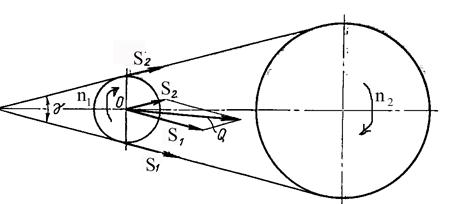
Rice. 72. Scheme to the power transmission calculation.
From the equilibrium condition of the driving pulley
 (12.4)
Taking into account (12.2) the circumferential force on the drive pulley
Leading branch tension
 , (12.6)
Traction of the driven branch
 . (12.7)
Drive pulley shaft pressure
 . (12.8)
The relationship between the tension forces of the leading and driven branches is approximately determined by the Euler formula, according to which the tensions of the ends of a flexible, weightless, inextensible thread covering the drum are connected by the dependence
Where is the coefficient of friction between the belt and the pulley, is the angle of the pulley wrap.
The average value of the coefficient of friction for cast iron and steel pulleys can be taken: for rubber-fabric belts = 0.35, for leather belts = 0.22 and for cotton and woolen belts = 0.3.
When determining the friction forces in the V-belt transmission, instead of - coefficient, friction it is necessary to substitute the reduced coefficient of friction for V-belts into the formulas
 , (12.10)
Where is the angle of the belt wedge.
When considering together the given force ratios for the belt, we obtain the circumferential force on the drive pulley
![]() , (12.11)
, (12.11)
Where is the thrust coefficient, which is determined by the dependence
An increase in the circumferential force on the drive pulley can be achieved by increasing the pre-tension of the belt or by increasing the thrust coefficient, which increases with the increase in the wrap angle and the coefficient of friction.
The tables with reference data on the characteristics of the belts indicate their dimensions, taking into account the required traction coefficients.
Geometric calculation . The estimated length of the belts with a known center distance and pulley diameters (Fig. 71):
Where . For end belts, the length is finally coordinated with the standard lengths in accordance with GOST. For this, a geometric calculation is performed according to the scheme shown in Fig. 73.
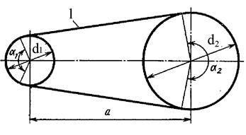
Fig. 73. Scheme for the geometric calculation of the belt drive
According to the finally established length of a flat-belt or V-belt open transmission, the actual center distance of the transmission is subject to the condition that
Calculation formulas without taking into account the sagging and initial deformation of the belt.
Belt wrap angle of the drive pulley in radians:
 , (12.14)
In degrees  .
.
The procedure for performing design calculations. For a belt drive, during the design calculation according to the given parameters (power, torque, angular, speed and gear ratio), the dimensions of the belt and drive pulley are determined, which provide the necessary belt fatigue strength and the critical coefficient of thrust at maximum efficiency. According to the selected diameter of the drive pulley, the remaining dimensions are determined from a geometric calculation: ![]()
Design calculation of flat belt transmission according to traction capacity, it is produced according to the permissible useful voltage , Which is determined by the sliding curves. As a result of the calculation, the width of the belt is determined by the formula:
 , (12.15)
Where is the circumferential force in transmission; - permissible specific circumferential force, which corresponds to the maximum thrust coefficient, which is determined at a belt speed = 10 m / s and a wrap angle = 1800; - the ratio of the location of the gear, depending on the angle of inclination of the line of centers to the horizontal line: = 1.0, 0.9, 0.8 for the angles of inclination = 0 ... 600, 60 ... 800, 80 ... 900; - coefficient of the angle of the pulley wrap; - speed coefficient:; - coefficient of the operating mode, which is taken: = 1.0 quiet load; = 0.9 load with small changes, = 0.8 - load with large fluctuations, = 0.7 - shock loads.
For the calculation, the diameter of the drive pulley is preliminarily determined using empirical formulas
 , (12.16)
Where is the transmitted power in kW, is the rotational speed.
Drive pulley diameter is rounded to the nearest standard.
The type of belt is adopted, according to which the permissible specific circumferential force is determined according to table 12.1.
Table 12.1
Parameters of flat drive belts
The estimated belt width is rounded to the nearest standard width according to table 12.2.
Table 12.2 Standard width flat drive belts
|
20, 25,32, 40, 50, 63, 71, 80, 90, 110, 112, 125, 140, 160, 180, 200, 224, 250, 280… |
|
|
30, 60, 70, 115, 300… |
Table 12.3 Width of a rim of a flat belt pulley.
Design calculation of V-belt transmission according to the traction capacity, it is produced according to the permissible power transmitted by one belt of the selected cross-section, which is also determined from the sliding curves. As a result of the calculation, the number of belts of the selected section is determined by the formula:
|
d 1, mm |
P0 (kW) at belt speed υ, m / s |
||||||
|
l 0 = 1320mm |
|||||||
|
l 0 = 1700mm |
|||||||
|
l 0 = 2240mm |
|||||||
|
l 0 = 3750mm |
|||||||
|
l 0 = 6000mm |
Conversion of the designation system for the cross-sections of V-belts in accordance with GOST 1284 into international standards: O - Z, A - A, B - B, C - C, G - D, D - E, E - E0
1120; 1180; 1250; 1320; 1400; 1500; 1600; 1700; 1800; 1900; 2000; 2120; 2240; 2360;2500
2650; 2800; 3000; 3150; 3350; 3550; 3750; 4000
4250; 4500; 4750; 5000; 5300; 5600; 6000
6300; 6700; 7100; 7500; 8000; 8500; 9000; 9500; 10000; 10600
The calculated number of V-belts shall be rounded to the nearest higher whole number.
Checking calculation for durability . The durability of a belt is determined by its resistance to cyclic fatigue. Fatigue resistance is determined by the number of loading cycles, which increases with increasing belt speed and decreasing belt length. To ensure the durability of the belt within 1000 ... 5000 hours of operation, the number of belt runs per second is checked, which corresponds to the number of loads per second
Table 12.7


Table 12.7
Dimensions and parameters of V-belts
|
Designation |
section, mm |
F, mm2 |
|||||||||
|
Normal section |
|||||||||||
| 4.1 out of 5 based on 7 votes | |||||||||||
A good understanding of gear ratio calculations will allow you to fine-tune the performance characteristics of your cars - namely, acceleration and maximum speed... Gear ratios determine the load on the engine, which affects acceleration and top speed. Knowledge the right way Changes in gear ratios or other vehicle elements based on accurate calculations can make the difference between winning and losing. In addition, gear ratios are the basis for most other calculations related to operational characteristics car, so it is good to know how to determine these ratios.
Gear ratios tell you how much the transmission is downshifting. Internal combustion engines have too much rpm and too little torque to be efficient when the engine is connected directly to the wheels. The car will hardly go anywhere with the current wheels, or you will need to use coin-sized wheels. Just as a hoist allows a mere mortal to lift tons of weight alone, downshifting in your car's drivetrain multiplies the torque to increase a small amount of engine torque, and this reduces the revs. crankshaft to an acceptable value so that the wheels rotate at a more suitable speed.


More than two gears

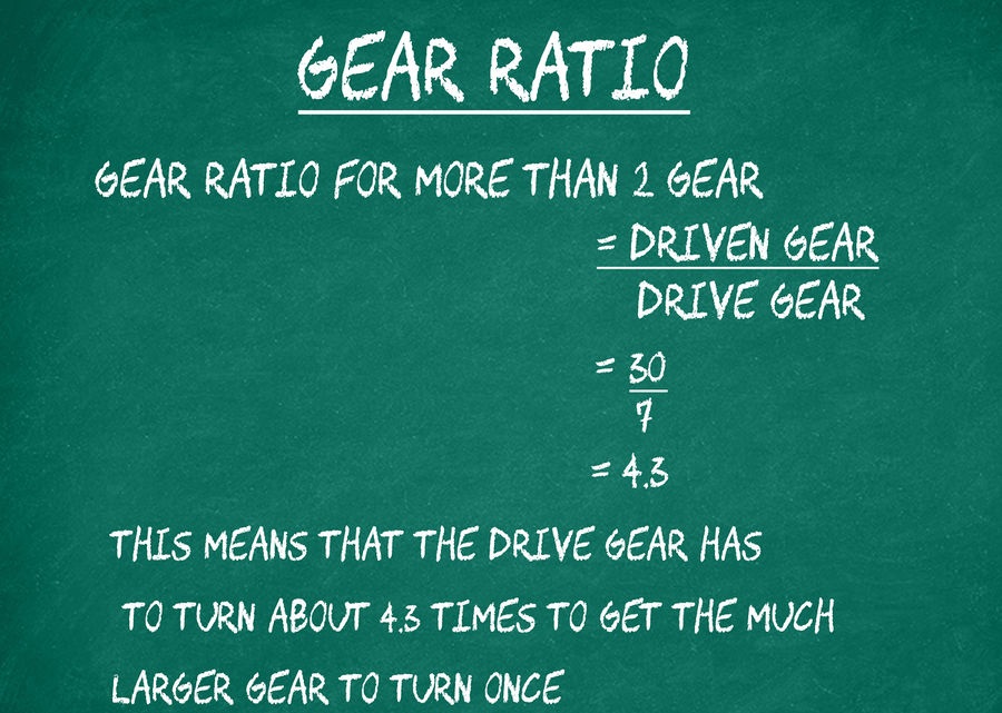

In other words, the gear ratio describes how the initial energy received from the engine or any other source of energy (water, wind wheel, turbine, etc.) changes during its transmission. Throughout the history of the development of technology, mankind has created a wide variety of transmissions, for each of which there is a gear ratio, which is the quotient of dividing the speed of the leading link by the speed of the follower.
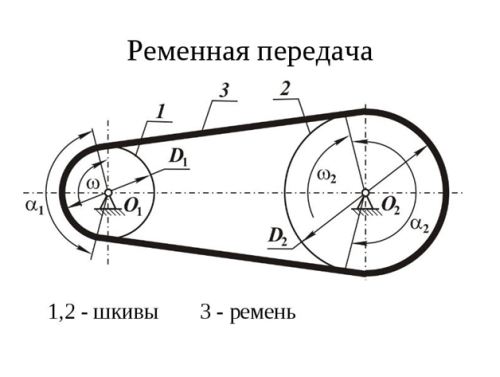
Belt drive refers to the two pulleys that connect the belt, as shown in the figure. It is possible that it was one of the first methods used by humans. The material used for the manufacture of the belt changed, its shape changed, but the gear ratio remained unchanged, defined as the frequency of dividing the speed of the drive shaft by the speed of the driven shaft, or as a result of dividing the number of revolutions of these shafts (n1 / n2 or? 1 /? 2) ... For a belt drive, it can be calculated using the diameters (radii) of the pulleys. The gear ratio in this case is also determined as the quotient of the division of revolutions. If, during the conversion of energy, the number of revolutions decreases, that is, the gear ratio is greater than 1, then the gear will be reduced, and the device itself is called a gearbox. If the result is less than one, then the device is called a multiplier, although it also performs the functions of a reducer, only a reduction. The gear ratio of the gearbox allows you to reduce the number of revolutions (angular velocity) coming from the drive shaft to the driven shaft, while increasing the transmitted torque. This property of the gearbox makes it possible for engineers to achieve when designing various devices for changing the parameters of the transmitted energy, and the gear ratio of the gearbox serves as a powerful tool in solving this problem. Despite its considerable age, there is still work on the car for the belt drive, it is used as a drive for a generator, a gas distribution mechanism, and also in some other cases.
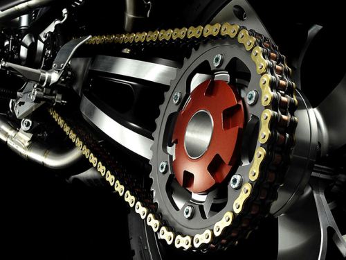
A distinctive feature of the chain drive is the increased noise level, as well as wear when working at high speeds, therefore, if it is necessary to use it, it is best to set it after reducing the speed. In a car, it is possible to use a chain drive for a timing drive, however, a limitation of this application is the increased noise level during its operation.
GEAR RATIO
This is the name of a mechanism that uses wheels with meshing teeth. It is considered the most rational and demanded for mechanical engineering. There are many different options for the manufacture of such wheels, differing in the arrangement of the axles, the shape of the teeth, the method of their engagement, etc. As in the case of a chain, for a gear, the gear ratio is determined by dividing the number of teeth of the gears (z2 / z1). The variety of options for constructing a gear train makes it possible to use them in different conditions, from a low-speed gearbox to high-precision drives.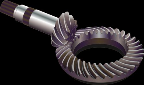

With any use of a planetary gear, one of its three elements will be stationary. In such a planetary version of the construction of gears, in relation to a simple gear or belt, it is possible to obtain a significant change in torque with a small number of wheels and dimensions of the device. In a car, such a planetary device has its own scope - as part of automatic transmissions, as well as in hybrid vehicles, to ensure joint ICE operation and an electric motor. The planetary gearbox is widely used in tracked vehicles.
ABOUT THE MAIN COUPLE
Almost all types of gears are used in a car - the torque from the engine goes through a chain of various devices and undergoes changes, starting from the gearbox, main pair, and ending with the wheels of the car. All gear ratios for the gearbox and the main pair directly affect the dynamics of the vehicle. Therefore, in order to ✔ reduce the switching frequency; ✔ the ability to drive with a quiet ride at low engine speeds; ✔ increasing the upper threshold of the speed of movement, the gear ratios, including for the main pair, must be reduced. To improve acceleration dynamics, everything should be the other way around. The operation of various mechanisms and devices, including in a car, cannot take place without converting the energy used, both in magnitude and in direction. The gear ratio helps to estimate and calculate the magnitude of the required change, as well as its consequences.Belt transmission is called a kinematic mechanism that transfers energy using a flexible connection using friction between the belt and the pulley.
The constituent parts belt drive are located at some distance from each other driving and driven pulleys, which are bent around by a special drive belt.
Transfer load level at belt drive depends on factors such as belt tension, coefficient of friction and pulley wrap angle.
Belt transmission
Belt transmission there are different types and are classified according to the shape of the belt cross-section. According to this criterion, experts distinguish round-belt, V-belt and flat-belt transmissions. At the same time, V-shaped and flat belts are most common in technology.
The main advantage of flat belts is that their stress at the points of contact with the pulleys is minimal, and wedge-shaped belts are that, due to their profile, they are characterized by increased traction capacity. As for round belts, they can most often be found in machines and mechanisms that have relatively big sizes, for example, appliances, bench-top machines, equipment for the food and clothing industry.
Advantages and disadvantages of belt drivesThe main advantages that have belt drives are the following: simple design and low cost; the ability to provide transmission of torque over long distances; ease of operation and maintenance; unstressed work and smooth running.
At the same time, belt drives have a number of disadvantages, which should be attributed to: relatively large dimensions that do not allow their use in a number of cases; fragility when used on high-speed mechanisms; the inability to ensure a constant gear ratio due to belt slippage; heavy loads on supports and shafts.
It should also be emphasized that reliability belt drives significantly lower than other types of transmissions, since it is not excluded and quite often there are belt breaks and their jumping off the pulleys. This is why belt drives require more attention from a maintenance point of view and must be constantly monitored.
Types of flat belt transmissionsDepending on how the pulley axles are located, as well as on their purpose, flat-belt drives are divided into the following types: open gears, gears with stepped pulleys, cross gears and gears with a tension roller.
Open gears are characterized by parallel axes and the fact that the pulleys rotate in the same direction.
Gears with stepped pulleys provide the ability to change the angular speed of rotation of the driven shaft at a constant speed of the drive shaft.
In cross gears, the pulleys rotate in opposite directions, and their axes are parallel.
Idler pulley gears ensure belt tension in automatic mode and increasing the wrap angle of a small diameter pulley.
The main materials for the manufacture of flat belts are leather, woolen, rubberized and cotton fabrics, and they can have different widths. Which of them are used in each specific case depends on the purpose of the belt and the conditions of its operation. In addition, the load that the belt will experience during the transmission operation is of no small importance.
The design of a flat-belt transmission is relatively simple, it can be successfully used when high speed characteristics kinematic mechanisms and large distances between the axes of the pulleys.
V-belt transmissionThe main feature of a V-belt transmission is that its drive belt has a trapezoidal section with a profile angle equal to 40 °... Compared to a flat belt, it is capable of transmitting sufficiently large tractive forces, however Efficiency it is significantly lower.
The main function of any drive belt is the transmission of traction, and therefore it needs to be strong, wear-resistant, durable, provide good adhesion to the pulleys, and at the same time be relatively inexpensive.
Main scope of use V-belt transmissions- machines and mechanisms with small center distances and large gear ratios. In this case, the axes of the shafts are most often located in a vertical plane.
Timing beltsTiming belts are most often made from a durable and modern synthetic material such as polyamide. They quite successfully combine the advantages that gearing and flat belts have.
These belts have small projections on their working surfaces, which, during operation, enter into small recesses located on the pulleys. They are well suited for those gears that transmit rotation at high speeds, and the center distance is small.
Belt pulleysFor flat-belt transmissions, the most preferred shape of the running surface that the pulley has is a smooth surface with some convexity. As for the V-belts, they have the side surfaces of the pulleys as workers. Pulleys are made from materials such as steel, plastics, aluminum alloys and cast iron.


