The main mechanisms of the engine internal combustion are the connecting rod-crank and distribution, and the main systems are the power supply, ignition, lubrication and cooling systems.
The connecting rod-crank mechanism is designed to convert the rectilinear reciprocating movement of the piston into the rotational movement of the crankshaft. This mechanism (Fig. 53) consists of cylinder 5, piston 4, with rings, piston pin 3, connecting rod 2, crank 1 of the crankshaft.
The piston stroke depends on the crankshaft crank radius and is equal to twice the crank radius. The extreme positions of the piston, both upper and lower, correspond to the positions when the axis of the crank shaft, the centerline of the connecting rod and the axis of the piston pin are located on one straight line. These positions are called dead positions of the piston because the force on the piston cannot be made to rotate. crankshaft... The entire system can be removed from this position only by external forces - by the force of inertia of the flywheel or by the movement of the pistons of other cylinders, if the engine is multi-cylinder.
The cylinders of most engines are made in the form of separate bushings cast from special cast iron, inserted into the holes of the cylinder block. The cylinder block is one of the main parts of the engine. The upper part of the block is closed by a head, which contains intake and exhaust valves, nozzles or glow plugs.
The lower part of the block is connected to a crankcase, which, in some engines, serves as the base for the crankshaft main bearings, and a chamber in which oil is placed in a four-stroke engine for lubricating parts.
The cylinder block (also the head) is usually made with two walls; water circulates in the space between the walls to cool the engine. It has a cylindrical shape. Its bottom can be both flat and shaped in order to improve the conditions for mixing air and fuel in the combustion chamber of diesel engines.
In the middle part, the piston has lugs on the inside, called bosses, in the holes of which a finger is placed, connecting the piston to the connecting rod. The lower, thinnest part of the piston is called the skirt. The piston diameter is usually less than the cylinder diameter, and there is a necessary temperature gap between the piston and the cylinder, in which a thin oil film forms, lubricating the rubbing surfaces.
On the outer side surface of the piston there are annular grooves into which piston rings... Some of the rings create seals between the walls of the cylinder and the piston (the so-called compression rings), while some of the rings (oil-cutting) serve to remove excess lubricant from the cylinder walls. Oil control rings usually have a groove, this increases the specific pressure of the ring on the cylinder walls, as a result of which it better removes excess oil from the cylinder surface.
The piston pin is a hollow rod made of alloy steel. To reduce wear, the working surface of the finger is usually cemented, rolled and ground. In many engines, the piston pin is secured only against longitudinal movement by spring locks in order to exclude the possibility of friction against the cylinder walls. With this fastening, the pin can rotate both in the piston bosses and in the connecting rod bushing. A free-floating finger will wear more evenly.
A connecting rod pivotally connects the piston to the crankshaft and transfers the forces received by the piston to the shaft. The connecting rod of internal combustion engines is steel and, as a rule, stamped. It consists of a rod and two heads: the upper one with a bronze bushing pressed into it and the lower one, called a crank and fitted with liners. The cross-section of the bar is usually I-beam, which gives it the necessary strength with a low weight.
The crank head of the connecting rod is split; The detachable part is called the cover and is bolted to the main part. These bolts are subjected to very heavy loads and are made of strong chromium steel. The connecting rod bushings, like the main bearing bushings, are made in the form of thin-walled steel wide half rings. The inner working surface of these liners is filled with antifriction alloy, babbitt or lead bronze.
The crankshaft is the most critical engine component. It has several main bearing journals and crank journals, or simply cranks, the number of which corresponds to the number of cylinders. For balancing, the crankshaft is equipped with counterweights attached to the crank cheeks from the side opposite to the crank journal. A flywheel is usually attached to the end of the shaft.
The distribution mechanism controls the supply of air or a combustible mixture to the cylinder at strictly defined moments and removes combustion products from the cylinder also at certain moments.
In four-stroke engines, the gas distribution is perceived as a mechanism consisting of valves. 6 (see Fig. 53), covering the holes in the block head; springs that hold the valves closed; camshaft and transmission parts - pushers, bushings, rocker arms, etc.
The camshaft, which has cams, is driven from the crankshaft through a gear train. The cams on the shaft are located in a certain sequence. "When the camshaft rotates, the cams, running on the pushers, raise them. This movement of the pushers is transmitted to the ends of the swinging rocker arms, the second ends of which press on the valve stems, and, compressing the springs, open them in a strictly established order ...
The valves operate at high temperatures, so they are made of special heat-resistant steels.
The power system is designed to supply fuel or a combustible mixture to the engine cylinders necessary for the work process. Diesel power supply systems and carburetor engines are different.
The general scheme of the diesel power supply is shown in Fig. 54. Fuel from the tank 3 through the supply valve 4 enters the coarse filter and, passing through it, goes to the booster pump 32. This pump drives the fuel through the fine filter, from where it goes to the fuel pump high pressure 33. The pump under high pressure at certain times supplies fuel to the injectors 26 located in the head of the engine block.
The air supplied to the cylinder must be clean, free from dust, therefore it is purified by passing it through a special air cleaner. For the normal operation of the power system, it is very important to have good condition filters and air cleaners: untimely cleaning disrupts the operation of the power system and impairs engine performance.
The power supply system of a carburetor engine includes a fuel tank, a sump, a carburetor, an air line and an engine speed regulator. The most critical part in this system is the carburetor. It is designed to prepare a combustible mixture, i.e. a mixture of fuel vapors with a well-defined amount of air.
There are several designs of carburetors. In fig. 55 shows the device of the simplest carburetor.
Mixing chamber 1 is a pipe section in which atomized fuel is mixed with air. This ka-
1 - cover; 2 - tank filter; 3 - fuel tank; 4 - consumable valve; 5 - fuel line of the tank; 6 - air release bolt; 7 - a cap of the coarse filter; 8 - element cover; 9 - filter element; 10 - rod hairpin; 11 - coarse filter housing; 12 - drain plug; 13 - fuel line of the coarse filter; 14 - filter element; 15 - vertical channel of the body; 16 - fine filter housing; 17 - mounting plate; 18 - filter housing cover; 19 - spring washer, 20 - spring; 21 - ball of the purge valve; 22 - nut of the fine filter seal; 23 - blower valve; 24 - a tube of the filtering element, 25 - a tube for removing the fuel leaking through the nozzle; 26 - nozzle; 27 - vortex chamber; 28 - compression chamber; 29 - high pressure fuel line; 30 - backflow fuel line; 31 - pump manual paging; 32 - booster pump; 33 - fuel pump; 34 - regulator leash; 35 - regulator; 36 - pressure fuel line; 37 - fuel line to the pump; 38 - drain plug; 39 - the cover of the lower measure has a local constriction, called diffuser 3, to which the atomizer 4 is led, supplying fuel to the chamber.
The air, passing through the mixing chamber, increases its speed in the diffuser, and a vacuum is created above the atomizer, which contributes to better suction of fuel, which is then carried away by the rapidly moving air stream, evaporates, mixes well with the air and enters the cylinders.
Fuel is supplied to the atomizer through a float chamber 7 with a float 10 designed to maintain the same fuel pressure in the atomizer 4, which is ensured by maintaining a constant fuel level. There is a check valve 9 in the chamber, and for a deliberate increase in the fuel level, there is a button 8, by pressing which the valve is opened. In the channel 6 on the way from the float chamber 7 to the atomizer 4 there is a nozzle 11 made in the form of a plug with a precisely calibrated hole through which a limited amount of fuel is passed.
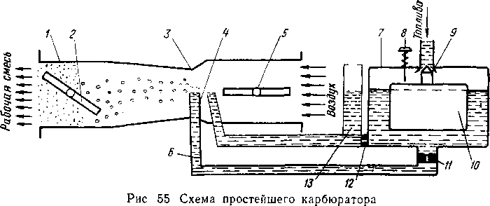
Throttle valve 2 serves to regulate the amount of mixture supplied to the cylinder: at greater opening throttle more mixture enters the engine cylinders, so the engine develops more power. On the contrary, by closing the throttle valve, the mixture access to the cylinders is reduced, as a result of which the engine power is reduced.
The fuel mixture supplied to the cylinders can be "lean" or "rich" depending on the ratio of air to fuel. The higher the percentage of the fuel, the richer the mixture. The air damper 5 serves to temporarily enrich the mixture, mainly at the time of starting the engine and establishing its operating mode. This enrichment is achieved by turning the air damper, which reduces the free cross-section of the channel, as a result of which the air flow rate increases, a greater vacuum is created, and the fuel supply through the main nozzle 11 increases.
It is important to have a constant quality mixture for proper engine operation. The simplest carburetor does not provide this consistency. When the throttle valve is closed, the engine speed decreases and a lower vacuum is created above the spray nozzle, as a result of which the fuel outflow will be weaker and the mixture will flow into the cylinders lean.
On the contrary, when the throttle valve is fully opened, the fuel outflow increases and the mixture becomes richer.
The elimination of this drawback in carburetors is achieved by setting up an additional device called a compensation jet D. It is placed between the float chamber and the compensation well 13, through which the fuel channels are connected to the atmosphere. Due to this, a constant amount of fuel is supplied through the compensation nozzle regardless of the vacuum in the diffuser, i.e. regardless of the engine operating mode.
With an increase in the engine speed, the fuel supply through the main main jet 11 will increase and the mixture will be enriched, at the same time the air intake will increase, but since the compensation jet 12 will supply the same amount of fuel, the quality of the mixture will be the same.
With a decrease in engine speed, the main jet will begin to lean the mixture, at the same time, the compensation jet, supplying the same amount of fuel with less air intake, will enrich the mixture, as a result, its quality will not change.
The ignition system of the carburetor engine (Fig. 56) ensures the receipt and distribution of high voltage current (15,000-20,000 V), which is necessary for the formation of a spark in the spark plugs, which ignites the working mixture in the cylinder.
The ignition system includes: current sources - a storage battery 10 and a generator 1 with a relay-regulator 12, an ignition coil 4, a variator 5, a breaker 2 with a capacitor 3, a distributor 7, spark plugs 6, an ignition switch 8 and low and high voltage wires ...
Breaker 2 consists of a cam with a number of protrusions equal to the number of engine cylinders, a fixed contact (anvil) and a movable contact (hammer), which, when the cam rotates, is squeezed by each protrusion and breaks
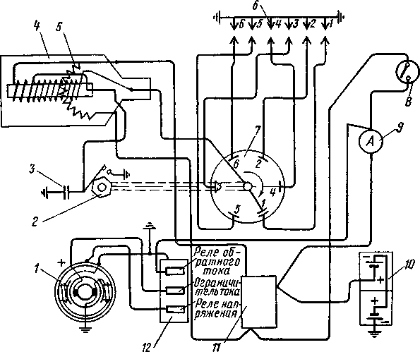
Rice. 56. Ignition scheme of a carburetor engine:
1 -¦ generator; 2 - breaker; 3 - capacitor; 4 - ignition coil; 5 - variator; 6 - spark plugs; 7 - distributor; 8 - ignition switch; 9 - ammeter; 10 - rechargeable battery; 11 - starter switch; 12 - relay-regulator contacts. The chopper is connected to a distributor consisting of a rotor and segments according to the number of cylinders, and sits on the same roller rotating from the engine camshaft 2 times slower than the rotation of the crankshaft.
At the moment of opening the breaker contacts, the magnetic flux created by the primary winding disappears; his lines of force cross the turns of the secondary winding, inducing a high voltage current in it, which is supplied to the rotor of the breaker and through the corresponding segments to the spark plugs.
In the operation of the ignition system, the following two points should be distinguished. When the ignition switch is on and at low engine speeds, the low voltage current flows through the following circuit: negative pole of the battery - ground - closed contacts of the breaker - primary winding of the ignition coil - variator - ignition switch - ammeter 9 - positive pole of the battery. The high voltage current flows through the following circuit: secondary winding of the ignition coil - distributor rotor - distributor segments - spark plugs - earth - accumulator battery- starter switch 11 - ammeter - ignition switch - variator - primary winding - secondary winding of the ignition coil; at the same time, a spark jumps between the rotor and the segment, as well as between the electrodes of the spark plug, the latter ignites the working mixture in the cylinder.
At medium and high engine speeds, the ignition system works in the same way as at small ones, only with a change in the circuits for the passage of low and high voltage currents due to the fact that the power supply of the system is automatically switched by the relay-regulator 12 to power from the generator. The low voltage current in this case flows through the circuit: negative terminal of the generator - ground - breaker contacts - primary winding of the coil - variator - ignition switch - regulator relay - positive terminal of the generator.
The high voltage power supply circuit also changes, namely: secondary winding - distributor rotor - distributor segment - spark plug - ground - negative terminal of the generator - winding of its armature - relay-regulator - ignition switch - variator - primary winding - secondary winding.
As the engine speed increases, the time of the closed state of the breaker contacts decreases and due to the reaction of the e. etc. with. self-induction, the low voltage current does not have time to reach the required value, the magnetic field created by it weakens, as a result the high voltage drops and the motor runs unstable.
To eliminate this phenomenon, a variator (resistance spiral) is included in the primary winding circuit, which, when the low voltage current decreases, cools down, its resistance decreases, as a result of which the primary winding current increases, and

Fig. 57. The spark plug therefore increases the high voltage current. At a low engine speed, the variator protects the ignition coil from overheating. Capacitor 3, connected in parallel with the contacts of the breaker, weakens the sparking and protects the contact from burning.
The spark plug (Fig. 57) consists of a steel body 5 screwed into the socket of the block head, a core b made of insulating material, a thin steel rod 2, which acts as a central electrode. Opposite the lower end of the central electrode, there is a side electrode 1 fixed in the candle body. The gap between these electrodes forms a spark gap of 0.5-0.7 mm, through which an electric spark slips.
The assembled plug body and core are separated by a gasket 4.
In the upper part of the spark plug there is a nut 8 with a washer 7. To prevent gas leakage from the cylinders, the plug is screwed into a socket on a copper-asbestos gasket 3. A high voltage wire is connected to the upper end of the central rod, secured by a nut.
Lubrication of the rubbing surfaces of the engine is of great importance for its operation. No matter how well the rubbing surfaces are treated, friction arises between them, for which energy is wasted, resulting in increased wear of the surfaces and overheating of the rubbing parts.
Lubrication of rubbing surfaces is nothing more than the separation of these surfaces from each other with a thin layer of grease. Due to the fact that the adhesion force of the lubricant particles to each other is less than the adhesion force of the lubricant particles to the surface of the rubbing parts, friction arises not of metal on metal, but friction in the liquid layer.
The lubricant continuously supplied to the friction surface carries away, in addition, the smallest particles of worked metal and cools the rubbing surfaces.
The oil used to lubricate rubbing surfaces, depending on the nature of the lubricated surfaces and their mode of operation, must have certain qualities. So, it must have the necessary viscosity so as not to be squeezed out of the gap between the surfaces, to have sufficient resistance to inflammation, and not to contain acids, alkalis and solid impurities.
The rubbing surfaces of the engine are lubricated by splashing, forced oil supply, and also in a combined way. Most in a simple way the lubricant is splashing. In this case, fast-moving parts (mainly of the connecting rod-crank mechanism) grab oil from the lower part of the crankcase and spray it over the entire surface in the form of tiny droplets. Excess grease flows back into the oil sump of the crankcase
However, this method does not provide proper lubrication of parts in hard-to-reach places. More reliable lubrication is carried out by a forced method, when oil is supplied to the rubbing surfaces under pressure by a special pump, usually of a gear type, driven from the engine crankshaft
The forced lubrication system includes a pressure gauge to show the oil pressure in the line, a thermometer to measure the oil temperature, as well as a waste oil cooler, sump and filters. In engines, a predominantly combined lubrication system is used, in which individual surfaces are lubricated by splashing, and the most critical places are lubricated under pressure.
Engine cooling system. When the engine is running, a large amount of heat is generated, as a result of which the heating temperature of the parts rises, and if you do not take measures to cool them, the engine will overheat and normal operation will be disrupted
When overheated, the oil loses its viscosity, the lubrication conditions deteriorate, the oil begins to burn out, accelerated wear of parts sets in, and seizures can appear on the working surfaces, leading to accidents.
Cooling in engines is achieved mainly by passing cooling water through the cavities between the double walls of the cylinder parts and the block head. Water, washing the hot walls of the parts, takes away some of the heat. The cooling system includes cavities of cooled parts, lines, radiator, pump, fan.
If the cooling water circulates due to the difference in density between heated and cold water, then such a system is called thermosyphon. In this case, the water that has taken away some of the heat from the walls of the cooled parts rises up and enters the radiator, giving way to colder water coming out of the radiator. The radiator of this system must be located above the cooled parts.
The thermosiphon system does not cool the parts efficiently enough, therefore, modern engines a cooling system with forced circulation of water from a water pump of predominantly centrifugal type is used.
The radiator consists of two tanks (upper and lower), interconnected by side pillars and a core, which consists of a row of vertical tubes passed through horizontal plates that increase the cooling surface. For greater efficiency, the radiator is cooled by the air flow generated by the fan.
To make starting the engine easier, especially in winter, hot water is poured into the cooling system. Some powerful engines use starting motor, the cooling system of which is connected to the cooling system of the main engine. When running, the starter motor heats the water in common system cooling, which makes it easier to start the main engine.
The internal combustion engine consists of a crank mechanism, a gas distribution mechanism and five systems: power supply, ignition, lubrication, cooling and start-up.
crank mechanism designed to perceive the pressure of gases and convert the reciprocating movement of the piston into the rotational movement of the crankshaft
The gas distribution mechanism is used to perform the internal combustion engine cycles
The power system is designed to prepare and supply a fuel mixture of the desired quality and quantity or portions of atomized fuel at a certain moment into the engine cylinder during the intake process.
The ignition system is used to forcibly ignite the working mixture from an electric spark that occurs between the electrodes of the spark plug under the action of a high voltage electric current pulse.
The lubrication system is used to continuously supply lubricant to the friction units of moving parts.
The cooling system is designed for forced removal of heat from heated parts. Cooling systems are liquid and air, when parts are cooled by air flow.
The starting system is designed to start the engine quickly and reliably.
End of work -
This topic belongs to the section:
INTERNAL COMBUSTION ENGINES
Faculty of MiAS ... Discipline content ... Introduction Internal combustion engines Role and application ...
If you need additional material on this topic, or you did not find what you were looking for, we recommend using the search in our base of works:
What will we do with the received material:
If this material turned out to be useful for you, you can save it to your page on social networks:
| Tweet |
All topics in this section:
The role and use of internal combustion engines in construction
An internal combustion engine (ICE) is a piston heat engine, in which the processes of fuel combustion, the release of heat and its transformation into mechanical work occur directly
Brief history of ICE development
The first internal combustion engine (ICE) was invented by the French engineer Lenoir in 1860. This engine largely repeated steam machine, worked on lamp gas on a push-pull cycle
Theoretical and actual cycles
The nature of the working process in the engine is different - the heat supply (combustion) occurs at a constant volume (near TDC, these are carburetor engines) or at a constant pressure
1.7.3. The compression process serves: 1 to expand the temperature limits between which the working process takes place; 2 to ensure the maximum
Heat transfer during compression
In the initial period of compression after closing the intake valve or the purge and exhaust ports, the temperature of the charge filling the cylinder is lower than the temperatures of the walls, head, and piston crown. Therefore, in the lane
Indicators of efficiency, economy and design excellence
Indicator indicators: Fig. twenty. Indicator diagram four-stroke
Indicators of toxicity of exhaust gases and ways to reduce toxicity
The starting materials in the combustion reaction are air containing about 85% carbon, 15% hydrogen and other gases and hydrocarbon fuel containing about 77% nitrogen, 23% oxygen.
Flammability limits of air-fuel mixtures
Rice. 24. Combustion temperatures of gasoline-air combustible mixtures of different compositions: T
Combustion in carbureted engines
In carburetor engines, by the time a spark appears, a working mixture consisting of air, vapor or gaseous fuel and residual gases fills the compression volume. Process
Detonation.
Detonation is a complex chemical-thermal process. External signs of detonation are the appearance of ringing metallic knocks in the engine cylinders, a decrease in power and engine overheating.
Combustion in diesel engines
Features of the combustion process, Fig. 28: - fuel supply starts with an advance by an angle θ to TDM. and ends after VMT; - pressure change from t.
Forms of combustion chambers of diesel internal combustion engines
Unseparated combustion chambers. In undivided combustion chambers, Fig. 29, the improvement of the process of atomizing fuel and mixing it with air is achieved
Crank and gas distribution mechanisms
3.1. The crank mechanism (Fig. 33) is designed to perceive the pressure of gases and convert the reciprocating movement of the piston into the rotational movement of the crankshaft.
Pressurization, purpose and methods of pressurization
Engine cylinder charging can be either dynamic or carried out using a special supercharger (compressor). There are three systems of pressurization with the help of superchargers:
Engine power systems
4.1 Diesel power supply system. The fuel system supplies fuel to the cylinders. At the same time, high power output must be ensured.
Power supply system for carburetor engines
Preparation and supply of a combustible mixture to the cylinders of carburetor engines, regulation of its quantity and composition is carried out by the power supply system, the work of which has a great
Contact transistor ignition system
KTSZ began to appear on cars in the 60s. With an increase in the compression ratio, the use of poorer working mixtures and with an increase in the crankshaft speed and the number of valve cylinders
Non-contact transistor ignition system
BTSZ began to be used in the 80s. If in the KSZ the breaker directly opens the primary circuit, in the KTSZ - the control circuit, then in the BTSZ (Fig. 61-63) there is no breaker and the control becomes contactless
Microprocessor-based engine control systems
MSUD began to be installed on cars from the mid-80s on cars equipped with fuel injection systems. The system manages the engine for optimum performance and
Distributor cover
The outer surface of the distributor cap as well as the ignition coils must be kept clean. For tall "Zhiguli" covers, the impulse flow down the outer surface onto the body is distributed
Spark plug
Spark plugs are used to generate the electrical spark needed to ignite the working mixture in the engine cylinders.
Breaker contacts
The reliability of the classic ignition system (KC3) is largely interrupter dependent. It often happens that about the breaker (by the way, as well as about other elements of the ignition system)
Lubrication and cooling and starting systems
The main provisions: The engine lubrication system is designed to prevent increased wear, overheating and seizure of rubbing surfaces, reduce the cost of indicators
Cooling system
V piston engines during the combustion of the working mixture, the temperature in the engine cylinders rises to 2000-28000 K. By the end of the expansion process, it decreases to 1000-1
Starting system
Start of piston motors sec., regardless of the type and design, is carried out by rotating the crankshaft of the engine from an external source of energy. In this case, the speed should be about
Fuel
Fuel for internal combustion engines - products of crude oil refining (gasoline, diesel fuel) - The main part of it is hydrocarbons. Gasoline is obtained by condensation of light fractions of oil refining
Engine oil
7.3.1. Requirements for engine oils In piston engines, oils of mainly petroleum origin are used to lubricate parts. Physicochemical properties of oils due to
Coolants
The cooling system removes 25-35% of the total heat. The efficiency and reliability of the cooling system is highly dependent on the quality of the coolant. Cooling requirements
TO Category:
Cars and tractors
The main mechanisms and systems of the internal combustion engine of motor tractors
The internal combustion engine (Fig. 4) consists of the following mechanisms and systems that perform specific functions.
The crank mechanism carries out the engine's working cycle and converts the rectilinear, reciprocating movement of the piston into the rotational movement of the crankshaft. The mechanism consists of a cylinder with a head, a piston with rings, a piston pin, a connecting rod, a crankshaft, a flywheel. The mechanism is installed in a crankcase, closed from below by a sump (oil reservoir).
The gas distribution mechanism is designed for the timely admission of a combustible mixture or air into the cylinder and the timely removal of exhaust gases. It consists of valves with guide bushings, springs with their fastening parts, rods 4, rocker arms, pushers, a camshaft and camshaft drive gears.
The cooling system is used to remove excess heat from heated engine parts. It can be liquid or air. If the cooling system is liquid, then it consists of a cooling jacket, radiator, water pump, fan, thermostat and pipes. System air cooling consists of heat dissipating fins, a fan, a casing and shields that direct the air flow to dissipate heat.
The lubrication system supplies oil to the rubbing parts of the engine in order to reduce friction between them and remove heat. It consists of an oil reservoir, oil pump, filters and oil lines.
The fuel system is used to prepare a combustible mixture and supply it to the cylinder (carburetor engines) or to supply fuel to the cylinder and fill it with air (diesel engines).

Rice. 4. The device of a single-cylinder carburetor engine
For carburetor engines, this system consists of fuel tank, fuel lines, fuel and air filters, fuel pump, carburetor (or mixer), intake and exhaust pipes, muffler.
Have diesel engines the power system consists of the same parts and devices, with the only difference that a high-pressure fuel pump and an injector are installed instead of the carburetor.
The ignition system is designed to forcibly ignite the working mixture from an electric spark. It includes devices that provide high voltage electric current, wires and candles.
Diesel engines do not have ignition system devices, since the fuel ignites when it comes into contact with compressed air at a high temperature.
The starting system is designed to start the engine. It includes: launcher Gas engine with a transmission mechanism (on a tractor), an electric starter on a car and sometimes on a tractor, a decompression mechanism, water and air heating devices.
Two-stroke engines have the same basic mechanisms and systems as four-stroke engines, but differ in the design and operation of the gas-fired mechanism. definitions.
TO Category: - Cars and tractors
An engine is a machine that converts some form of energy into mechanical work.
On modern cars and tractors, internal combustion heat engines are used, in which the process of fuel combustion and the conversion of the heat released during this into mechanical work occurs inside the engine cylinder.
All internal combustion engines are usually classified according to:
- the kind of fuel used - engines running on liquid fuel (gasoline or diesel fuel), and engines running on gaseous fuels (compressed and liquefied gas);
- the method of mixture formation and ignition of the working mixture - engines with external mixture formation and electric ignition of the working mixture (carburetor) and engines with internal mixture formation and ignition of fuel from high temperatures of compressed air (diesel);
- the way of carrying out the working cycle - four-stroke engines, in which the working cycle is completed in four strokes (piston stroke) or in two revolutions of the crankshaft, and two-stroke engines, in which the working cycle is performed in two strokes (one revolution of the crankshaft) ;
- number and arrangement of cylinders - single-cylinder and multi-cylinder engines; single-row (cylinders are located in one row) and two-row (V-shaped), when two rows of cylinders are located at an angle to each other;
- working volume;
- cooling method - with liquid or air cooling.
The choice of the type of engine depends on its purpose and the requirements imposed on it in terms of fuel, overall dimensions, power and other indicators. Forestry tractors use four-stroke multi-cylinder diesel engines, which are often started with single- and two-cylinder two-stroke carburetor engines. Cars typically use four-stroke, multi-cylinder, carbureted or diesel engines with an electric starter.
The main mechanisms and systems of the internal combustion engine
The internal combustion engine (fig) consists of the following mechanisms and systems.
1 - camshaft drive gears,
2 – camshaft, 3 - pushers,
4 - rods, 5 - piston, 6 - cylinder head,
7 - rocker arms, 8 - springs, 9 - carburetor,
10 - guide sleeve, 11 - spark plug, 12 - valve, 13 - cylinder, 14 - cooling jacket, 15 - piston pin, 16 - crankcase, 17 - connecting rod, 18 - flywheel, 19 - crankshaft, 20 - oil pan ...
2. Basic concepts and definitions of the engine.
Piston 2 reciprocates and can take two extreme positions - upper and lower. The rectilinear movement of the piston by means of the connecting rod 3 and the crank 4 is converted into the rotational movement of the crankshaft 5.
The position of the piston in cylinder 1 at which it is farthest from the engine crankshaft axis is called top dead center (TDC), and the position at which the piston is closest is called bottom dead center (BDC).
The distance traveled by the piston from one dead center to another is called the piston stroke (S). The part of the working process performed in one piston stroke is called a stroke. Each piston stroke corresponds to a 180º rotation of the crankshaft (half a turn).
The movement of the piston is accompanied by a change in volume between the piston crown and the cylinder head.

1 - cylinder, 2 - piston,
3 - connecting rod, 4 - crank,
5 - crankshaft.
The space (volume) formed at TDC above the piston is called combustion chamber volume(Vc).
The volume released by the piston when it moves from TDC to BDC is called working volume of the cylinder(Vh).
where D is the cylinder diameter, mm; S - piston stroke, mm.
The volume formed above the piston, when it is positioned at BDC, is called full cylinder volume(Va) and includes the working volume of the cylinder and the volume of the combustion chamber.
The sum of the working volumes of all cylinders, expressed in liters, is called the engine displacement (V "h).
Where i is the number of engine cylinders.
Total cylinder volume ratio Va to the volume of the combustion chamber Vc named compression ratio (ε).
![]()
The value of the compression ratio (ε) shows how many times the working mixture or air in the cylinder is compressed when the piston moves from BDC to TDC.
An engine is a machine that converts some form of energy into mechanical work.
On modern cars and tractors, internal combustion heat engines are used, in which the process of fuel combustion and the conversion of the heat released during this into mechanical work occurs inside the engine cylinder.
All internal combustion engines are usually classified according to:
- the kind of fuel used - engines running on liquid fuel (gasoline or diesel fuel) and engines running on gaseous fuel (compressed and liquefied gas);
- the method of mixture formation and ignition of the working mixture - engines with external mixture formation and electric ignition of the working mixture (carburetor) and engines with internal mixture formation and ignition of fuel from high temperatures of compressed air (diesel);
- the way of carrying out the working cycle - four-stroke engines, in which the working cycle is completed in four strokes (piston stroke) or in two revolutions of the crankshaft, and two-stroke engines, in which the working cycle is performed in two strokes (one revolution of the crankshaft) ;
- number and arrangement of cylinders - single-cylinder and multi-cylinder engines; single-row (cylinders are located in one row) and two-row (V-shaped), when two rows of cylinders are located at an angle to each other;
- working volume;
- cooling method - with liquid or air cooling.
The choice of the type of engine depends on its purpose and the requirements imposed on it in terms of fuel, overall dimensions, power and other indicators. Forestry tractors use four-stroke multi-cylinder diesel engines, which are often started with single- and two-cylinder two-stroke carburetor engines. Cars typically use four-stroke, multi-cylinder, carbureted or diesel engines with an electric starter.
The main mechanisms and systems of the internal combustion engine
The internal combustion engine (fig) consists of the following mechanisms and systems.
1 - camshaft drive gears,
2 - a camshaft, 3 - pushers,
4 - rods, 5 - piston, 6 - cylinder head,
7 - rocker arms, 8 - springs, 9 - carburetor,
10 - guide sleeve, 11 - spark plug, 12 - valve, 13 - cylinder, 14 - cooling jacket, 15 - piston pin, 16 - crankcase, 17 - connecting rod, 18 - flywheel, 19 - crankshaft, 20 - oil pan ...
2. Basic concepts and definitions of the engine.
Piston 2 reciprocates and can take two extreme positions - upper and lower. The rectilinear movement of the piston by means of the connecting rod 3 and the crank 4 is converted into the rotational movement of the crankshaft 5.
The position of the piston in cylinder 1 at which it is farthest from the engine crankshaft axis is called top dead center (TDC), and the position at which the piston is closest is called bottom dead center (BDC).
The distance traveled by the piston from one dead center to another is called the piston stroke (S). The part of the working process performed in one piston stroke is called a stroke. Each piston stroke corresponds to a 180º rotation of the crankshaft (half a turn).
The movement of the piston is accompanied by a change in volume between the piston crown and the cylinder head.
1 - cylinder, 2 - piston,
3 - connecting rod, 4 - crank,
5 - crankshaft.
The space (volume) formed at TDC above the piston is called combustion chamber volume(Vc).
The volume released by the piston when it moves from TDC to BDC is called working volume of the cylinder(Vh).
where D is the cylinder diameter, mm; S - piston stroke, mm.
The volume formed above the piston, when it is positioned at BDC, is called full cylinder volume(Va) and includes the working volume of the cylinder and the volume of the combustion chamber.
The sum of the working volumes of all cylinders, expressed in liters, is called the engine displacement (V "h).
Where i is the number of engine cylinders.
Total cylinder volume ratio Va to the volume of the combustion chamber Vc named compression ratio (ε).
![]()
The value of the compression ratio (ε) shows how many times the working mixture or air in the cylinder is compressed when the piston moves from BDC to TDC.