- Design characteristic
- Reducing gear (creeper)
- Gears: some properties
- Motoblock bevel gear
- Gear reducer: nuances
In addition to the basic devices needed in the economy, and the performance of various works, there are those, the use of which improves, facilitates the use of the basic mechanisms. They also increase their functionality and economy. These include homemade reducer, which can be assembled from the spare parts at hand.
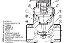
Scheme of the device and operation of the reducer: a - gas does not flow through the reducer; b - gas passes through the reducer, 1 - fitting, 2, 3 - pressure gauge, 4, 8 - springs, 5 - valve, 7 - membrane, 9 - screw, 10 - chamber, 11 - valve.
Design characteristic
A reducer is a design of all kinds of gears, shafts, transmission chains, which reduces the rotation of the output shaft and increases its torque.
- from gears;
- worm;
- a combination of the first two;
- single and multi-stage.

Here are some materials and tools that will be needed, it is impossible to list them all, since work can be performed in various types of them:
- screwdrivers, wrenches of various shapes and sizes;
- ruler, vernier caliper;
- drills, files;
- pliers;
- rubber gaskets;
- hammer, vice;
- bolts, washers, bearings, pipe cuttings, pulleys, gears, shafts;
- steel sheets or frame from an old gearbox;
- self-welding machine (inverter).
Back to the table of contents
Reducing gear (creeper)
Its first element is the body, the location and interaction of all parts inside depends on it. Axles and shafts, gears, thrust bearings, nests for them - this is its design. Cast iron or aluminum alloys are used for industrial designs. For its self-assembly, either an old frame is required, or you can weld it from steel. When welding, it must be taken into account that the metal is deformed, reduced, therefore, a little allowance is left for processing the main landing nests.
For the case, they also take a 2-inch plumbing square. Gears are taken from old non-working chainsaws, pulleys from a washing machine.
There is another build option. Boring work is not done, it is completely welded, and pipe segments are taken as bearing seats. They are exposed as needed and then fastened by welding, bolts.

The top part is removable, the bottom is equipped with a hole to drain the old oil.
The axial shafts are equipped with gears. Often, in a single-stage design, only the first are used, and the landing is carried out in an interference fit, spitz, key. With this arrangement, the gears move with the shafts. The axle is used in the presence of an intermediate gear that makes the direction of the shafts the same. It rotates freely along the axis with a minimum of clearance. Protect from side displacement with bumpers, washers. The shafts are made of 10-45 steel, with good machinability.
Bearings are supports. It is they who take all the load when moving inside the device. Functioning and efficiency depend on them. For homemade device suitable for closed type, they require minimal maintenance, they are lubricated with grease. Their design depends on the arising efforts. If the device has spur gears, then single or double-row simple ball gears will do. With a helical or worm gear, it is recommended to install roller, thrust-radial, since the load is greater.
Back to the table of contents
Gears: some properties
They provide engagement and change the rotation on the output shaft. They are made with special tools for metal, it is better to take them from old devices. The gaps between the shafts and the frame assembly depend on their parameters.
Between them it is necessary to carefully adjust the gap, this will give resistance to loads and reduce the noise of the device. Lubrication is carried out with liquid ordinary oil, it is poured to the level of its coverage of the lower gear.
Outlets are decorated with stuffing box gaskets, this will eliminate oil leakage, they are usually fixed in the bearing caps.
The device uses a safety clutch and bearing caps. The first allows you to avoid the destruction of the insides of the device from a heavy load. The second are deaf and cross-cutting.
The idea of how to make a homemade gearbox for a walk-behind tractor was taken from the "Modelist-Constructor" magazine, the design of the unit was redesigned in accordance with the following requirements: exclude the chain transmission from the transmission design, ensure the lowest possible center of gravity. Since the required gearbox was missing, the transmission was made from spare parts for the gears for the engine of the "Electron" scooter.
Motoblock: 1 - engine; 2 - casing; 3 - gas tank; 4 - ignition coil; 5 - switch; 6 - pin for fixing the angle of inclination of the working body (not conventionally shown in the top view); 7 - bolt М16; 8 - axis of attachment of the working body; 9 - working body (plow); 10 - holder; 11 - frame; 12 - carrier with control handles; 13 - a wheel with grousers.
We make a homemade gearbox for a walk-behind tractor
To make a homemade gearbox for the walk-behind tractor, parts were taken from the B-150 M engine: crankcase, gears, chain sprockets, as well as an additional gearbox shaft. The crankcase must be cut into two halves and removed from it the kickstarter, gearshift mechanism and crankcase. At the exit point of the kickstarter, it is required to install a plug and weld it using argon welding.
In the left half of the crankcase, we install the bearing box of the right running wheel of the walk-behind tractor. A spare crankcase of the same engine is used as the axle box.
A part of the crankcase of the V-150 M engine is also used as the left cover, which is supplemented with one part - a duralumin bushing. The bushing is pressed into the crank chamber and has a hole corresponding to the diameter of the shank of the engine output shaft.
Walk-behind tractor

- 1 - right wheel;
- 2 - left wheel;
- 3 - gear wheel of the first transfer;
- 4 - drive shaft;
- 5- reducer;
- 6 - driving gear;
- 7 - bushing;
- 8 - locking screw;
- 9 - drive shaft housing;
- 10 - axle box flange;
- 11 - nut and bolt M8;
- 12 - splined bushing;
- 13 - shaft;
- 14 - nuts М14;
- 15 - washer;
- 16 - stuffing box;
- 17.18 - bearings;
- 19 - engine.
Drive shaft of the walk-behind tractor

- 1,2 - cantilever parts of the shaft (from the secondary shafts of the V-150 M gears);
- 3 - toothed wheel (from the gear wheel of the first gear V-150M);
- 4 - the front part of the shaft (rod d22 mm);
- 5 - cut-off bead.
The motor and gearbox are fixed relative to each other by means of an M10 screw.
How to make a homemade walk-behind tractor with an ant gearbox
Chain reducer with two stages is designed to reduce the rotational speed and increase the torque transmitted from the output shaft power unit walk-behind tractor on wheels or cutters.
Chain reducer drawing
1 - body made of channel No. 20); 2 - cover from st. sheet s5); 3 - gasket made of oil-resistant technical plate) 4 - leading sprocket of the second stage (z = 11, t = 19.05); 5-key; 6 - bearing 206 (2 pcs.); 7- compensation sleeve; 8 - shaft; 9 - nut М22х1.5 with a spring washer; 10 - stuffing box; 11 - distance sleeve with keyway; 12-eccentric bearing housing (StZ, 2 pcs.); 13 - screw M8 with a spring washer (30 pcs.);
![]()
14 - driven sprocket of the second stage (z = 25, t = 19.05); 15- bearing 3008 (2 pcs.); 16 - bearing housing; 17 - sealing sleeve; 18 - left semiaxis; 19-oil drain plug (screw M10); 20 - the bottom of the case from st. sheet s4); 21 - oil filler plug (screw Ml0); 22.23 - oil seals (2 pcs.); 24 - right semiaxis; 25 - fixing screws M6 (8 pcs.); 26 - bolt М8; 27 - chain t = 19.05; 28 - driven sprocket of the first stage (z = 57, t = 12.7); 29 - distance sleeve
The first stage of the gearbox includes two sprockets with 17 and 57 teeth, respectively, with a pitch of 12.75 mm. The 17-tooth drive sprocket sits on the output shaft of the power unit, the driven sprocket sits on the outer flange input shaft second stage.
The second stage of the reducer is reinforced and made with a driving sprocket with 11 teeth and a driven sprocket with 25 teeth, a tooth pitch of 19.05 mm. Since during the operation of the walk-behind tractor, the second stage is located close to the cultivated soil, it is protected from dust by a closed crankcase, which is directly welded to the crossbars, the crankcase is welded by spars through steel spacers.
A strut is welded between the crankcase and the cross member for reliability. The crankcase is welded from two channels No. 2 with shelves, which are reduced in length to 35 mm. In the lower parts of the channels, the walls of the channels have the shape of a semicircle, instead of the cut-off shelves, the bottom is welded from a steel sheet of 4 mm, which is bent along the walls of the channels in the form of a semi-cylinder. The top of the crankcase is closed with a lid with a gasket made of oil-resistant technical plate.

In both walls, two coaxial holes d = 100 mm are made for the bearing housings. Around each of them, six other threaded holes with M8 threads are made evenly, the purpose of which is to fasten the bodies to the crankcase. The lower bearings of the semi-axles have normal housings, the upper bearings of the shaft have eccentric housings. By turning them around the axis by at least 15 °, the chain tension of the second stage of the gearbox is adjusted stepwise.
The shaft of the second stage of the gearbox is mounted in two ball bearings 206. By means of two spacers, the drive sprocket is fixed exactly in the middle between the inner walls of the crankcase and is connected to the shaft by means of a parallel key. On the centering boss of the right axle shaft sits a large driven sprocket, fixed with six M8 bolts between the opposite flanges of the axle shafts. The bottom of the large driven sprocket and part of the chain are permanently immersed in oil.
When the engine of the walk-behind tractor is running, the moving chain transfers oil to the upper part of the crankcase - thus, lubrication of the rubbing parts of the second stage is organized. To prevent oil leakage, gland seals are provided in the bearing housings. The axle shafts are rigidly flanged to form a single shaft mounted in two 308 ball bearings.
Making a gearbox for a walk-behind tractor with your own hands is a difficult and at the same time interesting task. This is one of the important mechanisms, without which the work of garden equipment using a walk-behind tractor is unthinkable. Its main task is to reduce the speed of the drive shaft and at the same time increase or decrease the torque to the drive.
You can buy a transmission mechanism for your walk-behind tractor in a specialized store, but it is wiser to assemble a gearbox with your own hands, taking into account all technical characteristics engine. This will the best option, since when designing a mechanism for a specific power plant, an individual calculation is made, which will simplify the task of pairing it with the engine.
When starting to manufacture a gearbox, it is necessary to clarify which type of mechanism is preferable for your walk-behind tractor. It depends not only on the power of the engine, but also on its layout, as well as on the level of complexity of the tasks.

Gearbox types
The design of any converting device for a walk-behind tractor (gearbox) consists of a set of shafts transmitting the movement or gear wheels of different diameters, enclosed in a robust case.
Converting devices are divided into several types according to the type of transmission:
- chain;
- belt;
- gear;
- worm (gear-worm);
- combined systems.
For chain-type gearboxes, rotation transmission is provided using a chain and different-sized sprockets, which are mounted on rotary shafts. The principle of operation of the belt mechanism is similar to the chain mechanism, but instead of sprockets and a chain, pulleys and a belt are used.
Inside the body of the gear reducer there are shafts with gears mounted on them, having straight or oblique teeth. Gears transfer rotation from the engine to moving parts. Bevel gears are used in angle gears for heavy motoblocks.
Types of mechanisms
According to the way of work and action, all converting mechanisms for walk-behind tractors are divided into several types:
- angular;
- downward;
- reversible with reverse speed (reverse gear reverse gear);
A bevel gear (bevel gear) is used to redirect rotational energy from the vertical drive to the horizontal plane.
Reducing the number of revolutions and increasing the power of the drive mechanism is provided by reduction gear reducers, or. They are considered the most reliable for the operation of a diesel or gasoline walk-behind tractor, which has air cooling... This allows them to be used for particularly heavy work - for example, for plowing heavy soil or harvesting potatoes using a potato digger.
How to make a homemade gearbox for a walk-behind tractor
For self-assembly of the converting device on the walk-behind tractor, you need to stock up on the following tools:
- vernier caliper and metal ruler;
- screwdriwer set different sizes, including oblique;
- pliers and wire cutters;
- saw for metal;
- electric drill with a set of drills for metal;
- vice;
- hammers - big and small;
- rubber gaskets.
If you decide to assemble a gearbox yourself for your walk-behind tractor, be sure to make an approximate calculation. This will help determine at least ratio and the type of conversion device you want.
Also, with the help of preliminary calculations, you can estimate the dimensions of the future transmission device.
To make the correct calculation, decide on the parameters of your engine. For calculations, it is necessary to clarify several data:
- Engine speed. However, this value is not constant: it is necessary to "add gas", and it will increase significantly. Therefore, the calculations are based on the basis - the number idle speed plus 10%.
- Estimated number of revolutions for the suspension axle. It is calculated taking into account the diameter of the wheels to determine the run-out per full revolution. Based on this, you can calculate at what speed the axis should rotate in order to ensure the most comfortable speed of the walk-behind tractor. This is an average of 3 to 5 km / h.
Consider a simple example: the engine idling power, taking into account an increase of 10%, is 600 rpm, and to achieve a speed of 3 km / h, a rotational speed of 200 rpm is required. Therefore, the design gear ratio is 3: 1. In other words, to reduce the speed of rotation of the axle by three times, in order to ensure the speed of movement of 3 km per hour, the torque is increased three times.
Step-by-step instructions for assembling a chain reducer
If you have certain skills, you can make a gearbox of any type with your own hands, but the easiest way is to assemble a small-sized mechanism with a chain drive. Materials for it are easier to find, they are reliable in work.

To make homemade chain mechanism, stock up on the following spare parts and materials:
- sprockets with the required number of teeth;
- driven shaft;
- cylindrical and eccentric bearings;
- protective cover;
- fasteners for connecting parts of the casing;
- chains with the required number of links.
When assembling a gearbox of any design, bearings must not be replaced with bushings. Distortions between the driving and driven parts are unacceptable.
An old gearbox housing can be used as a protective cover suitable size by drilling holes in it for fastening.
- The manufacture of a homemade gearbox for a walk-behind tractor begins with a drive sprocket fastening to the output shaft of the engine. You can use a key or flange to fix it. Even spot welding can be used depending on the design of the output shaft.
- The driven shaft must be turned on the machine. The asterisk is fixed on it in the same way as on the drive shaft.
- A more reliable way is to make a shaft from two semiaxes, at the ends of which flanges are machined. The driven sprocket is fixed between them, fastening the entire structure with bolts. In this version, the second stage sprocket will be fixed more precisely and securely.
- To protect the gearbox mechanism from dirt and mechanical damage, it is placed in a protective case, which also serves as a reservoir containing liquid lubricant for moving parts.
- In the protective casing (crankcase), holes are drilled for installing support bearings. The driven shaft is mounted on cylindrical bearings, and the driving shaft is mounted on eccentrics. Changing, by virtue of their design features, position in the seat within a radius of 15 °, the eccentric bearing also changes the position of the drive shaft, thus adjusting the chain tension.
It is necessary that the teeth of the sprocket attached to the driven shaft are immersed in lubricating oil... When the shaft rotates, all units of the chain reducer are uniformly lubricated.
- To ensure the tightness of the crankcase, oil seals and sealing gaskets are installed along the parting line and in the bearing seats. If standard gaskets are not suitable, a special low-resistance sealant can be used.
If the calculation of the gear ratio is done correctly, then the gearbox, carefully assembled taking into account all the design features of your walk-behind tractor, will provide smooth operation mechanisms are no worse than its industrial counterparts.
The invention relates to the field of mechanical engineering, and more specifically to reduction gears. The reduction gear contains high-speed and low-speed shafts and eccentrics, oriented in pairs opposite to each other by their eccentricities and rigidly mounted on the high-speed shaft. The eccentrics are brought into interaction with the low-speed shaft through two-arm levers, hinged in the housing. The leading arms of these levers are made with grooves covering each of its paired eccentrics, and the driven arms are brought into interaction with the low-speed shaft due to the intermediate links. Expansion of functionality is achieved. 5 p.p. f-ly, 5 dwg
1. Reduction gear
The invention relates to the field of mechanics, more precisely to devices transmitting rotary motion from an energy source to an actuator with a change in the number of revolutions towards a significant decrease.
Simply put, here we are talking about a compact reduction gear with a large gear ratio.
2. State of the art
There are many design solutions for gear-type devices. Gearboxes in most cases reduce the number of revolutions of the output shaft in relation to the number of revolutions of the drive shaft. At the same time, they provide a significant gain in torque on the output shaft. Basically, gearboxes consist of a system of gears mounted on shafts, stopped in bearings in a housing. The degree of reduction in the number of revolutions of the shaft at the exit from the gearbox compared to the number of revolutions of the drive shaft, that is, at the entrance to the gearbox, is called the gear ratio.
For stages of gearboxes, depending on the types of gearing, the following are typical, approximately, gear ratios: - for pairs of gears - 6 ... 8, that is, the degree of decrease in the initial number of revolutions of the drive shaft in relation to the number of revolutions of the driven shaft.
For pairs worm-worm wheel - 50. If it is necessary to lower the initial speed in a much larger number of times, several stages are used different types involving several shafts.
The type of transmission (reducer) is offered to your attention.
A large selection of types of gearboxes is presented in the atlas of designs "Machine parts", 3rd edition, Revised and enlarged, edited by Dr. Tech. Sciences, prof. D.N. Reshetova. M.: Mechanical Engineering, 1968, p. 360.
Neither here, nor in other available sources, nothing similar was found, similar in features, to the proposed technical solution in terms of the connections of the shafts mated to each other.
3. Disclosure of the essence of the proposal
FIG. 1 and 2, the gearbox is shown semi-schematically, since it is simple. According to these, FIGS. in the cylindrical recesses of the housing 1, two forked two-armed levers are installed - discs 2 and 3, with their forks oriented towards each other and assembled overlapping. The levers cover with their forks each its own eccentric 4 and 5, sitting on the shaft. By means of bushings 6 (to increase wear resistance). The eccentrics are rigidly mounted on the high-speed shaft 7, which rests, here, on the bearings 8 and 9. The sides of the levers opposite to the forks - discs 2 and 3 - are provided at the periphery with cylindrical holes with slots. In these holes inserted and spring-loaded to the levers 2 and 3 intermediate links - ratchet pawls 10 and 11. This is the subassembly of the body. The shaft is made integral with a hollow cylindrical glass 13, the inner working surface "in" which is equipped, for example, with a ratchet ring. With this crown, ratchet pawls 10 and subassemblies of the body are brought into interaction. Bearings 14 are pressed onto the shaft, with which this shaft is inserted into the cover 15 of the gearbox. This is how the sub-assembly of the gearbox cover is formed. Both subassemblies are assembled and fastened as in FIG. 1.
Landing surfaces can be provided both from the sides and from the ends of the common body. Also, mounting holes can be provided anywhere on the sides of the housing (not shown).
The operation of the reduction gear of this version is reduced to the following.
When the shaft 7 rotates, the eccentrics 4 and 5 turn the forked levers-disks 2 and 3 through the bushings 6 in opposite directions. In this case, for example, if the upper disc 2 rotates under the action of the eccentric acting through the insert 6 on the fork of this lever, in the direction of the arrow "b", then the upper - the ratchet pawl 11 rotates the glass 13, and therefore the shaft itself, also in the direction of the arrow " b ". (fig. 2)
In this case, the other disc 3 rotates in the direction of the arrow "g", sliding with its ratchet pawl 10 relative to the inner surface "c" of the glass. Rotating further, the shaft 7 turns the discs 2 and 3 with eccentrics 4 and 5, still in opposite directions. But now the lower ratchet pawl 10 of the disc 3 carries away the glass 13, and with it the shaft to rotation against the arrow "d", that is, towards the arrow "b". Thus, the rotation of the high-speed shaft causes the rotation of the low-speed shaft evenly, in the same direction, but with a decrease in the initial number of revolutions as many times as the teeth of the notch on the inner surface of the glass, and the eccentricities of the eccentrics are equal to half the steps between adjacent teeth of the notch of the glass 13.
For example, if 200 teeth with a pitch of 2 mm are made on the inner surface of the glass 13, then the circumference of the working surface of the glass will be 200 × 2 = 400 mm, and two spliced eccentrics with eccentricities of about 1.0 are required to rotate the low-speed shaft by 360 ° mm, then the gear ratio of the mechanism is 25.
If it is necessary to create devices with large gear ratios, the diameter of the glass working surface should be increased. At the same time, it is possible to increase the number of teeth on the inner surface of the glass, and also increases the space for placing the levers, improving the conditions for this and choosing the optimal lengths of their arms.
Another version of this gearbox is possible, but built on the same principle. Thus, as shown in FIG. 3 and 4, the high-speed shaft can be the shaft 7 of the electric motor itself or another source. The low-speed shaft is installed in the bearings of the housing 1. On the high-speed shaft 7 are fixed the same paired eccentrics 4 or 5 with opposite (that is, with opposite) arrangement of their eccentricities. The eccentrics are covered with "stones" 6 to increase their wear resistance. Each eccentric 4 or 5 with its own stone 6 is inserted into a forked or closed groove of its own two-armed lever 2 or 3. The second arms of these levers 2 or 3 are made with holes (as in the first version, however, there the holes were opened with grooves, but here the shoulders are ring-shaped). With these second arms, the levers 2 or 3 interact (as in the first embodiment) with the low-speed shaft 13, also due to the intermediate links - here the rollers 17, and not the ratchet pawls, with the springing of these links (rollers), as in the first embodiment , each of its own set, between its forked lever and the low-speed shaft These spring-loaded rollers 17 are placed in groups in the slots of the low-speed shaft 13 with their coverage by other, but ring-shaped arms of the levers 2 or 3 with the formation of overrunning clutches (here the low-speed shaft 13 and the internal figured parts of the overrunning couplings are made in one piece or connected with a key). The operation of the gearbox of this version is as follows.
When the motor shaft 7 rotates, one of the eccentrics 4 or 5 with its own stone 6 turns the fork of the outer two-armed lever 2, for example, in the direction of arrow "a" due to the wedging action of the rollers 17 of its one-way clutch. Then the low-speed shaft 13 turns in the same direction.
At this time, the fork 3 of the inner lever, turning against the arrow "a", that is, along the arrow "b", does idle, since the wedging properties of the clutches are opposite here. Then the fork 9 of the inner lever, turning in the direction of the arrow "A", draws the low-speed shaft to the turn, also in the direction of the arrow "a".
Thus, the two-armed levers 2 and 3, under the action of their eccentrics, oppositely oriented, make scissor-like movements and evenly turn the low-speed shaft in the same direction.
It should be borne in mind that this second version of the gearbox can provide an increase in torque on the low-speed shaft. So, from the scaled drawing of Fig. 4 it follows that the gain in the torque at the output from the gearbox with respect to the torque at the input is found from the ratio 1 of the arm length of the forked lever and the radius of the output shaft, i.e. 63:11, approximately 6. This means that if the right shoulder "l" with a length of 63 mm makes a path along an arc equal to double eccentricity, that is, 6 mm, for a whole revolution of the high-speed shaft, then the point belonging to the surface of the low-speed shaft, lying on the surface of a radius of 11 mm, passes a path equal to 6: 3 = 2 mm, that is, 69/2 = 34.5 revolutions of the low-speed shaft, with a circumference of 2 × 3.14 × 11 = 69 mm .. This is the transmission reducer number.
Finally, the device can be simplified in terms of the kinematic connection of the two-arm levers with the working surface of the glass, and hence the low-speed shaft.
FIG. 5 shows an embodiment, where the driving levers are not made in the form of disks (although they can also be disk), but in the form of levers hinged on the axes 16. The intermediate links here are eccentrics 18, spring-loaded to the working surface of the glass, that is, to the low-speed shaft ...
Here, at idle two-armed lever 2 to the right, in the direction of the arrow "A", the spring-loaded eccentric 18 slides relative to the working surface of the glass 13. During the return stroke, it carries the glass along due to the jamming action at point "B", and hence the low-speed shaft itself, bringing it into rotation.
It should be noted that simplified versions of devices of this type are presented here. In more complex cases, it is possible to manufacture a gearbox not with two two-armed levers and with two paired eccentrics, but with a group of two-armed levers and with a corresponding number of paired eccentrics located in groups, on one shaft, but in different parallel planes that are sequentially included in the work on the rotation of the common , now an elongated glass. Here the best power indicators and the best balance of the mechanism will be achieved.
4. Expected technical and economic efficiency
The proposed reduction gear can be used as a means of significantly reducing the number of revolutions of the low-speed shaft of any device of the "gearbox" type (by 300 ... 500 and more times), while allowing to some extent increase the torque on the output shaft at least at least 10 ... 30 times) if necessary. In addition, it allows the low-speed shaft to rotate not evenly, but impulsively, with vibration. To do this, you just need to perform the eccentrics of the pairs with different values of eccentricities or make them with adjustable eccentricities (if required). Here the low-speed shaft will rotate with twitching, impulsively. It can be advantageously used in mini-concrete mixers, conveyors, when working with materials prone to sticking, etc.
It is impossible to discard the simplicity of devices from the shields, the links of which do not require in the manufacture of complex equipment, such as, for example, in the manufacture of worm or gear drives. By varying the length of the lever arms and the value of the eccentricities, we change the gear ratio of the gearboxes.
We offer attention to the types of gearboxes that provide a multiple reduction in the initial speed. Let us compare in terms of the types of links both versions of gearboxes with the data in the table.
1. A reduction gearbox containing at least a high-speed and low-speed shafts mounted in bearings and kinematically connected to each other, at least a pair of eccentrics are rigidly fixed on the high-speed shaft, oppositely directed by their eccentricities and covered by each fork of one of the arms of the two-armed levers, the second the shoulders of these levers are introduced into interaction with the low-speed shaft through intermediate links, characterized in that the kinematic connection of the shafts is that the bearing of one shaft is installed at the end of the other, the low-speed shaft is made at the same time with a hollow glass with an inner working cylindrical surface, two-armed levers are introduced inside the glass, are hingedly installed in the body and interact with the glass by means of intermediate links.
2. A gearbox according to claim 1, characterized in that the intermediate links interacting with the low-speed shaft are made in the form of ratchet dogs spring-loaded to the levers.
3. A gearbox according to claim 1, characterized in that the intermediate links interacting with the low-speed shaft are made in the form of eccentrics spring-loaded to the working surface of the glass.
4. Reducer according to claim. 1, characterized in that the working surface of the glass is made with notches.
5. A gearbox according to claim 1, characterized in that the eccentrics are equipped with bushings put on them and installed between the eccentrics and forks.
6. A gearbox according to claim 1, characterized in that the hinge of the two-armed levers is provided by their installation on the axles.
Any owner is able to design not only undercarriage, but also Various types do-it-yourself gearboxes for a walk-behind tractor. In addition, showing ingenuity, you can independently design almost any attachment special equipment to expand the functionality of this unit.
The walk-behind tractor is designed to facilitate the work associated with the processing of small land plots.
The walk-behind tractor is an indispensable unit that makes it easier to process small land plots. This unit, in addition to cultivating the land, can be used when transporting small loads over short distances. The main technical parameter that can characterize the performance of the unit is the power power plant... There are two types of motoblocks:
- light, with a power plant with a capacity of up to 5 liters. with.;
- heavy, with a power plant of up to 10 horsepower.
Depending on the method of attachment attachments these units are divided into:
- motor cultivators;
- wheeled motoblocks.
They differ in that the equipment on the cultivator is mounted on the drive axle, and on the wheeled walk-behind tractor a special bracket is provided for this purpose.
Purpose and types of gearboxes
One of the most important structural elements of the unit is the gearbox.
The task of this device is to ensure the transmission of power and torque from the shaft of the propulsion system to the working attachment or the wheels of the unit.

The main part of the walk-behind tractor is the gearbox.
Due to the design of the gearbox, not only the transmission of power and torque occurs, but also its strengthening with a simultaneous decrease in the number of revolutions of the driven shaft.
By design, the gearbox for the walk-behind tractor can be made in several varieties. The main varieties are as follows:
- gear;
- gear-worm;
- chain;
- belt.
The gear reducer is a housing with shafts placed in it, on which bevel and cylindrical gears are mounted. Such gearboxes can be straight and angular.
Gear-worm gearboxes are used for vertical placement crankshaft power unit. The gearbox in its design includes a worm gear and a worm, which is a screw with a large-pitch thread applied to it. A feature of this type of gearbox is the ability to transmit torque at an angle with respect to the motor shaft.

Chain gearboxes are structurally complexes of sprockets of various diameters mounted on shafts, the rotation to which is transmitted by means of a chain.
The belt reducer is an analogue of a chain drive, only pulleys are used instead of sprockets, and a belt drive is used instead of a chain drive. The pulleys used in the belt reducer have special grooves to hold the belt in place.
Most often, the gearbox is installed on a walk-behind tractor of a worm-gear or chain type. In the device of powerful walk-behind tractors, gear-type gearboxes are used. Belt-type gearboxes are quite rare in the walk-behind tractor device, since belts tend to break and slip when the load on the unit increases.
Preparatory work
Before proceeding with the design of a home-made structure, it is required to carry out a calculation, as a result of which it is possible to determine:
- ratio;
- type of construction;
- the value of the torque indicator on the input and output shafts;
- the value of the loads exerted on the shafts of the device;
- dimensions of transfer devices.
You can make a homemade walk-behind tractor using chain-type gearboxes in its design. The use of this type of reducer in homemade walk-behind tractor is a compromise that provides parts availability with relatively high operational reliability and ease of assembly.
To carry out work on assembling a structural element of a walk-behind tractor, you will need to purchase:
- sprockets with a pre-calculated number of teeth that provide the required gear ratio;
- driven shaft;
- bearings required for mounting the unit shafts;
- chains to ensure chain transmission;
- metal corners to ensure the installation of the protective case;
- enclosure for protection.
A homemade gearbox is assembled only after preparing all the required technical components of the structure.
Assembly work
The assembly of the unit should begin with the installation procedure on the input shaft of the unit drive sprocket assembly. An asterisk can be attached to the device different ways... Depending on the type of shaft used in the construction of the unit, this structural element can be fixed using a keyed connection, a connection using flanges or using a spot welding method. The driven shaft is assembled from two semiaxes, at the ends of which counter flanges are made. The driven sprocket is installed on a seat located between the flanges, after which it is assembled into a general structure using a bolt connection.
It is possible to assemble the shaft without using half shafts and bolted connections. For this purpose, the entire shaft is manufactured using a lathe. Such a shaft is fixed using a keyed connection or using the spot welding method. The disadvantage of this device is the insufficient degree of fastening of the sprocket.
To ensure protection against the penetration of dirt and foreign objects into the chain drive, the unit is placed in a specially made protective case. In addition to protecting the gear, the housing acts as a reservoir for storing the fluid that lubricates the gear. Due to the lubrication, smooth functioning is ensured and the degree of wear of rubbing parts is reduced.
Coaxial seats are made in the housing, in which the ball bearings are mounted, which act as a support for the shafts. To mount the shaft, ball bearings are used, made in a conventional cylindrical housing. Installation of the drive shaft is carried out on ball bearings, which have an eccentric housing. Thanks to this, the eccentric can change its position in the seat by 15 degrees, simultaneously with the ball bearing, it changes the position of the drive shaft, which allows you to control the tension of the chain drive.
During operation, the oil provides lubrication of the second stage of the device and distribution of lubricant to all nodes of the chain drive. The tightness of the case ensures the use of oil seals and seals in its design.