All parts connecting rod piston group divided into categories and matched individually to each other.
Tolerance group, indicated by a letter and embossed on the piston crown, ...
... must match the group indicated on the cylinder liner.

The values of the diameters of the holes in the piston bosses, the connecting rod head and the outer diameters of the piston pin are divided into groups, and are indicated by paint.
On the piston pin, the group is marked with paint applied to its end or inner surface. It must match the group ...

... indicated on the piston pin boss.

On the connecting rod, the piston pin hole pattern is also marked with paint. It must either match or be adjacent to the group's finger.
We check the correctness of the selection of the connecting rod and the piston pin in the following way.
A finger lubricated with engine oil should move in the connecting rod head under the pressure of the thumb, but not fall out of the bushing.

On the side surface of the lower connecting rod head and the cover there is a serial number of the cylinder in which it was installed.

The numbers on the connecting rod cover and on the connecting rod itself must match and be on the same side.

The connecting rods supplied in spare parts do not have such markings, therefore, before disassembling them, make the marking of the connecting rods and caps in the same way as the factory ones, so as not to turn over or confuse the caps during assembly.
We heat the piston to a temperature of 60-80 ° C. It is allowed to heat the piston in hot water.
We introduce the connecting rod head between the piston bosses ...
… And press in the piston pin greased with engine oil with a hammer through a mandrel or a device.

We fix the piston pin on both sides with retaining rings.

ATTENTION
The protrusion on the connecting rod cover must be on the same side as the inscription ...

ATTENTION
... "FRONT" on the piston.

The liner seats are thoroughly cleaned of scale and corrosion.
Replace the sealing copper washers of the cylinder liners with new ones.
The sleeves are pressed in with light hammer blows through a wooden block.

With a set of probes, we check the protrusion of the sleeve above the plane of the block, which should be 0.02-0.10 mm.

We select the piston rings for the cylinders.
We install the rings one by one into the cylinder to a depth of 20-30 mm and measure the gaps with a feeler gauge. Compression rings should have a gap in the lock of 0.3-0.6 mm, oil scraper rings - 0.3-1.0 mm.

If piston replacement is not expected, check the width of the grooves using new piston rings.
We check the clearance at several points around the circumference of the piston. The value of the side clearance for compression rings should be 0.050-0.082 mm, for prefabricated oil scraper ring 0.135-0.335 mm.

In worn-out cylinders, you can install rings of the nearest repair size and, if necessary, saw off the ends to obtain a gap of 0.3 mm.
We put the rings on the piston, starting with the oil scraper ring.
Having opened the lock of the oil scraper ring expander, we install it in the lower groove of the ring, after which we bring the ends of the expander.

We put the oil scraper ring on the expander ...

… By the lettering on the piston crown.

The angle between the expander and the ring locks is 45 degrees.
Installing the lower compression ring ...

… With an inscription and a chamfer on the inner side of the ring towards the piston crown.

Install the upper compression ring.

Size groups of pins, pistons and connecting rods
You will need: keys "for 10", "for 12", "for 14", heads "for 15", "for 19", a hammer.
1. Remove the cylinder head (see. "Replacing the cylinder head gasket").
2. Remove the engine oil sump and crankcase gasket (see. "Replacing the oil sump seal").
3. Remove the oil pump (see. "Removal, repair and installation of the oil pump").
4. Unscrew the nuts 1 of the connecting rod bolts and remove the cover 2 of the connecting rod. If the cover fits snugly, knock it off with light hammer blows. Remove the insert from the cover.
5. Push the piston out of the cylinder and remove it with the connecting rod. Remove the bushing from the connecting rod.
Remove the piston with a connecting rod from the cylinder carefully so as not to damage the cylinder mirror. Check the marks on the connecting rod and its cover. If the marks are not visible, mark the connecting rod and cover with the cylinder number.
6. Remove the remaining pistons with connecting rods.
7. Remove the piston rings with a puller or, if it is missing, carefully unfold the rings at the locks.
10. Remove the remaining pistons from the connecting rods.
11. Wash all parts in gasoline. Remove carbon deposits from pistons. Remove carbon deposits from the piston ring grooves with a piece of an old piston ring.
12. Inspect the pistons. If they have seizures, traces of burnout, replace the pistons. Measure the piston diameter. If it is less than 95.4 mm, replace the piston. The piston diameter is measured in a plane perpendicular to the piston pin axis, 8.0 mm below the piston pin axis. The piston is installed in the cylinder with a clearance of 0.036–0.060 mm. The pistons are divided by diameter into five size groups: A, B, C, D, D. The letter markings are stamped on the piston crown. When matching the piston to the cylinder, the above clearance must be ensured. Utterly allowable clearance between the piston and the cylinder 0.25 mm. The piston-to-cylinder clearance can be determined by measuring the piston and cylinder. Spare parts are supplied with pistons of two repair sizes: with a diameter increased by 0.5 and 1.0 mm. On one of the bosses under the piston pin there is an inscription “409” (piston of nominal diameter), “409AP” (diameter increased by 0.5 mm) or “409BR” (diameter increased by 1.0 mm).
|
|
|
|
13. Measure the piston ring-to-piston groove clearance at several locations around the circumference of the piston. The clearance should be between 0.060–0.096 mm for compression rings and 0.115–0.365 mm for the oil scraper ring. If the clearances exceed the specified values, the rings or pistons must be replaced. |
14. Measure the clearances in the piston ring joints. To do this, insert the ring into the cylinder and push it with the piston like a mandrel so that the ring fits in the cylinder evenly, without distortions. Measure the gap in the lock (connector) of the ring with a feeler gauge; it should be within 0.3–0.6 mm for compression rings and 0.5–1.0 mm for oil scraper disks. If the clearance is greater than the specified, replace the ring. If the gap is less, you can file the ends of the ring with a file clamped in a vice, moving the ring up and down the file. |


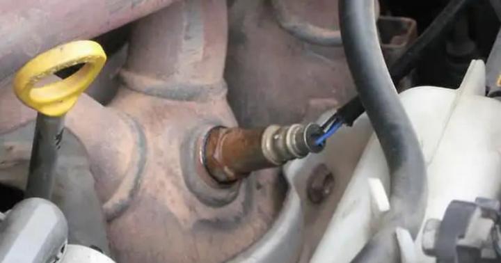
15. Check the seating of the piston pin in the upper connecting rod head. The gap between the pin and the bushing of the upper connecting rod head should be in the range of 0.0045-0.0095 mm. Pins, pistons and connecting rods are divided into four size groups and are marked with paint. The finger is marked on the inner surface at one end, the connecting rod - on the rod, the piston - on the lower surface of one of the bosses, or a Roman numeral is knocked out on the bottom of the piston.
Lightly lubricate the gudgeon pin with clean engine oil and insert into the upper connecting rod head. The finger should enter the head from the effort of the hand evenly, without jamming. The connecting rod must rotate on the piston pin under its own weight from a horizontal position. In an upright position, the pin should not protrude or fall out of the connecting rod head due to its own weight. Piston pin and connecting rod must be in the same size group or adjacent groups.
16. Pistons with piston rings, pins and connecting rods are selected by weight. The difference in weight for one engine should be no more than 10 g.
17. Inspect the connecting rod bushings. If they have scuffs, chipping or other damage, replace the liners.
18. Install the caps on the connecting rods and measure the diameter of the hole in the lower head of the connecting rod. The nominal hole diameter is 60 + 0.019 mm, the maximum permissible diameter is 60.03 mm. If the measured diameter exceeds the maximum permissible, replace the connecting rod with a cap. Measure the diameter of the bore in the upper connecting rod bushing. The nominal hole diameter is 22 + 0.007 –0.003 mm, the maximum allowable diameter is 22.01 mm. If the measured diameter exceeds the limit, replace the connecting rod. The dimensions of the connecting rod-piston group are given in table. 5.3.
Table 5.3 Rated and limit permissible sizes and landing of the mating parts of the connecting rod! piston group of the ZMZ engine! 409.10

* Tolerance 0.06 mm divided into 5 groups (every 0.012 mm)

19. Assemble piston 4 with connecting rod 3. Preheat the piston to a temperature of 60–80 ° C. Then quickly insert the connecting rod into the piston so that the inscription "Front" on the piston and the protrusion A on the connecting rod were on one side, and press in the piston pin 6
With a maximum tightness of 0.0025 mm. Install the circlip 5. Slide the piston rings onto the piston using a puller.
Insert the insert 7 into the lower head of the connecting rod - the fixing protrusion ("lock") on the insert should go into the recess in the lower head of the piston. Insert the insert 1 into the cover 2 of the connecting rod - the locking tab ("lock") of the insert should go into the recess in the cover. Lubricate the cylinder, piston 4, crankshaft connecting rod journal and liners 1 and 7 with clean engine oil. Orient the piston rings so that the compression ring locks are at an angle of 180 ° to each other, the oil scraper ring disc locks are also at an angle of 180 ° to each other and at 90 ° to the compression ring locks, the oil scraper ring expander lock is at an angle of 45 ° to the lock of one of the oil scraper discs. Turn crankshaft so that the connecting rod journal of the cylinder in which the piston is installed is at BDC. Insert the piston and connecting rod into the cylinder with the “Front” lettering on the piston boss facing the front of the engine (camshaft drive).
Using a special mandrel, crimp the piston rings and push the piston into the cylinder with light blows with a hammer handle, while the mandrel must be firmly pressed against the block, otherwise the piston rings may break. Move the piston down so that the lower head of the connecting rod sits on the connecting rod journal of the crankshaft, remove the hose cutters from the connecting rod bolts. Install the connecting rod cover 2 onto the connecting rod bolts so that the shoulder B on the connecting rod cover was on the same side as the ledge A on the lower head of the connecting rod; the cylinder numbers stamped on the connecting rod and cover were located on one side, and "locks" liners - against each other.

20. Wrap the nuts of the connecting rod bolts and tighten them to a torque of 68–75 N · m (6.8–7.5 kgf · m).
21. Install the rest of the pistons with connecting rods in the same way.
22. Turn the crankshaft several times; it should rotate easily, without jamming.
23. Install the oil pump, oil pan and cylinder head.
8
Repair of the UAZ engine overhaul restoration bulkhead
The grounds for disassembling and repairing the engine are: a drop in engine power, a decrease in oil pressure, a sharp increase in oil consumption (over 450 g per 100 km of run), engine smoke, increased fuel consumption, a decrease in compression in the cylinders, as well as noise and knocking. When repairing engines, it is necessary to take into account their design features. Engine cylinder block mod. The 4218, unlike the engine block of models 414, 4178 and 4021.60 with wet, easily removable liners, has a monolithic design with cast liners without seals. The sleeves in it are bored to the size of 100 mm (instead of 92 mm). The dimensions of the pistons, piston pins and rings have been increased accordingly. The pistons have a combustion chamber in the bottom. Piston pins have increased wall thickness, connecting rods - 7 mm longer. When disassembling the engine, carefully check the reusability of each part. The criteria for assessing the possibility of further use of parts are given in table. 2.1.
Engine performance can be restored by replacing worn parts with new nominal sizes or by restoring worn parts and using new oversized parts associated with them. For these purposes, pistons, piston rings, liners of connecting rod and main bearings of the crankshaft, inlet and outlet valve seats, bushings are produced. camshaft and a number of other parts and repair kits. The list of parts and kits of nominal and repair sizes is given in table. 2.2.
Values of clearances and tightness in the engine
A decrease or increase in clearances against the recommended ones worsens the lubrication conditions of the rubbing surfaces and accelerates wear. Reducing the tightness in stationary (press) landings is also highly undesirable. For parts such as guide bushings and plug-in exhaust valve seats, reducing the interference will impair the transfer of heat from these parts to the cylinder head wall. When repairing the engine, use the data in table. 2.3. (and table 2.3. part 2)
Removal and installation of the engine on cars of the UAZ-31512 family
Before removing the engine from a vehicle installed in an inspection ditch, do the following: 1. Drain the cooling system and the oil from the engine crankcase. 2. Remove air filter... 3. Disconnect the front exhaust pipe from the engine. 4. Disconnect the cooling system, heater and oil cooler hoses from the engine. 5. Disconnect and remove the cooling system radiator. 6. Disconnect the air and throttle valve rods from the carburetor. 7. Disconnect all electrical wiring from the engine. 8. Disconnect the clutch slave cylinder and the connecting rod from the clutch housing. 9. Remove the bolts securing the front engine mounts cushions together with the lower mounts cushions.
Rice. 2.41. Removing the engine from the vehicle
10. Install a special bracket on the second and fourth pins of the block head (Fig. 2.41), counting from the front end of the block. 11. Lift the engine with a hoist and disconnect the transmission from the engine. 12. Raise the engine and remove it from the vehicle, leaving the transmission with transfer case on the vehicle frame. Install the engine on the vehicle in reverse order. The engine can be removed by lowering it together with the gearbox and transfer case, it is necessary to remove the cross member. This method is much more complicated than the first.
Features of removal and installation of the engine on UAZ cars of wagon layout
To remove the engine, you must: 1. Follow the instructions in p. 1-10 of the section "Removal and installation of the engine on vehicles of the UAZ-31512 family". 2. Remove the seats and the hood cover. 3. Open the hatch in the cab roof, pass the hook with the cable (chain) of the lifting mechanism through it and hook the hook into the shackle. 4. Lift the engine a little and disconnect it from the transmission. 5. To make it easier to remove the engine, install a plank in the doorway that will not bend under the weight of the engine. 6. Lift the engine up to the opening in the hood with a lifting mechanism and, being careful, lift it out through the doorway along the plank. Install the engine in reverse order.
Disassembly and assembly of the engine
Thoroughly clean the engine from dirt and oil before disassembling. Disassemble and assemble the engine on a rotary stand using tool kits, for example, models 2216-B and 2216-M GARO, as well as special tools and accessories specified in Appendix 2. When using an individual method of repairing an engine, install parts suitable for further work on the former places where they worked. To ensure this, mark the pistons, piston rings, connecting rods, piston pins, liners, valves, rods, rocker arms and pushers when removing in any way that does not cause damage (punching, writing, paint, attaching tags, etc.). For any type of repair, you must not dismantle the connecting rod caps with connecting rods, rearrange the clutch housing and main bearing caps from one engine to another, or swap the middle main bearing caps in one block, since these parts are processed together. When replacing the clutch housing, check the alignment of the hole that serves to center the gearbox with the crankshaft axis, as well as the perpendicularity of the rear end of the clutch housing relative to the crankshaft axis. When checking, fasten the indicator stand to the crankshaft flange. In this case, the clutch must be removed. The runout of the hole and the end of the crankcase should not exceed 0.08 mm. After disassembling the engine, thoroughly degrease the parts, remove carbon deposits and tarry deposits. Remove carbon deposits from pistons, intake valves and combustion chambers mechanically or chemically. The chemical method for removing carbon deposits consists in keeping the parts in a bath with a solution heated to 80-95 ° C for 2-3 hours. To clean aluminum parts, use the following solution composition (in g per 1 l of water): Soda ash (Na2CO3) ..... 18.5 Laundry or green soap ..... 10 Liquid glass(Na2SiO3) ..... 8.5 To clean steel parts, use the following solution composition (in g per 1 liter of water): Caustic soda (NaOH) ..... 25 Soda ash (Na2CO3) ..... 33 Laundry or green soap ..... 3.5 Liquid glass (Na2SiO3) ..... 1.5
After cleaning the parts, rinse with hot (80-90 ° C) water and blow with compressed air. Do not wash aluminum and zinc alloy parts in solutions containing alkali (NaOH). When assembling the engine, observe the following: 1. Wipe and blow the parts with compressed air, and lubricate all rubbing surfaces with engine oil. 2. Threaded parts (pins, plugs, fittings), if they were turned out or were replaced during the repair process, install on the red lead. 3. One-piece connections (for example, a plug of the cylinder block) should be installed on nitro varnish. 4. Tighten the bolts and nuts with a torque wrench, tightening torque, N · m (kgf · m): Nuts of the studs securing the cylinder head ..... 71.6-76.5 (7.3-7.8) connecting rod ..... 66.7-73.5 (6.8-7.5) Nuts of studs securing the crankshaft main bearing caps ..... 122.6-133.4 (12.5-13.6 ) Nuts of the flywheel-to-crankshaft bolts ..... 74.5-81.4 (7.6-8.3)
Cylinder block repair
The pairing of the wearing parts is carried out mainly by replaceable parts, which makes it possible to repair the cylinder block by regrinding or replacing the liners, replacing worn out camshaft bushings with semi-finished ones, followed by processing them to the required size, replacing the crankshaft main bearing shells. The restoration of the operability of a pair of cylinder block bore-pusher due to their insignificant wear is reduced to replacing the pushers.
Repair and replacement of cylinder liners

Rice. 2.42. Extractor for extrusion of the liner from the cylinder block: 1 - puller; 2 - sleeve; 3 - block of cylinders
The maximum permissible wear of the cylinder liners should be considered an increase in the clearance between the liner and the piston skirt up to 0.3 mm. If there is such wear, press out the liner from the cylinder block using a puller 1 (Fig. 2.42) and bore to the nearest repair size of the piston with a machining tolerance of +0.06 mm. Do not clamp the sleeve into the chuck during machining, as this will deform the sleeve and distort its dimensions. Fasten the sleeve in the tool, which is a sleeve with landing collars with a diameter of 100 and 108 mm. Insert the sleeve into the bushing until it stops in the upper shoulder, which is clamped with a cover ring in the axial direction. After processing, the mirror of the cylinder liner should have the following deviations: 1. Ovality and taper of no more than 0.01 mm, with the larger base of the cone located in the lower part of the liner. 2. Barrel shape and corset - no more than 0.08 mm. 3. The runout of the cylinder mirror relative to the landing belts with a diameter of 100 and 108 mm is not more than 0.01 mm.

Rice. 2.43. Measuring the protrusion of the sleeve above the plane of the block
After pressing the liner into the cylinder block, check the amount of protrusion of the upper end of the liner above the upper plane of the block (Fig. 2.43). The amount of protrusion should be 0.005-0.055 mm. If there is insufficient protrusion (less than 0.005 mm), the head gasket may be punched; in addition, coolant will inevitably enter the combustion chamber due to insufficient sealing of the upper collar of the liner with the cylinder block. When checking the amount of protrusion of the end of the sleeve over the block, it is necessary to remove the rubber O-ring from the sleeve.

Rice. 2.44. Clamp for sleeves: 1 -nut; 2 - washer; 3 - bushing
To prevent the liners from falling out of the slots in the block during repairs, secure them with washers 2 and bushings 3 put on the cylinder head mounting studs, as shown in Fig. 2.44. After worn out, replace the cylinder liners bored to the third repair size of the piston with new ones.
Cylinder head repair
The main defects in the cylinder head that can be eliminated by repair include: warping of the contact plane with the cylinder block, wear of seats and valve guides. The non-straightness of the plane of the head in contact with the block, when checking it on the control plate with a probe, should not be more than 0.05 mm. Eliminate slight warpage of the head (up to 0.3 mm) by scraping the plane along the paint. For warpage exceeding 0.3 mm, the head must be sanded.
Replacing the piston rings
Replace the piston rings after 70,000-90,000 kilometers (depending on the operating conditions of the vehicle). Piston rings are installed three on each piston: two compression rings and one oil scraper. Compression rings are made of special cast iron. The outer surface of the upper compression ring is porous chrome plated, and the surface of the second compression ring is tin plated or has a dark phosphate coating.

Rice. 2.45. Installation of rings on the piston: a - piston with rings engine UMP-4178.10; b, c - piston with rings of the UMZ-4218.10 engine; 1 - piston; 2 - upper compression ring; 3 - lower compression ring; 4 - annular discs; 5 - axial expander; 6 - radial expander
Grooves are provided on the inner cylindrical surfaces of both compression rings (
rice. 2.45, a), due to which the rings turn out somewhat when the piston moves downward, which contributes to better removal of excess oil from the surface of the liners. The rings must be installed on the piston with the grooves up, towards the piston crown. The UMZ-4218.10 engine can be equipped with two versions of compression rings (Fig. 2.45, b, c). One version of the upper compression ring 2 (Fig. 2.45, b) has a groove on the inner cylindrical surface. The ring must be installed on the piston with the groove up. Another version of the upper compression ring 2 (Fig. 2.45, c) has a barrel-shaped profile of the outer surface, there is no groove on the inner cylindrical surface of the ring. The position of the ring when installed in the piston groove is indifferent. The lower compression ring 3 (Fig. 2.45, b, c) is of the scraper type, on the lower end surface it has an annular groove, which, together with the tapered outer surface, forms a sharp lower edge ("scraper"). The ring is made in two versions - with a groove on the inner cylindrical surface of the ring (Fig. 2.45, b) and without a groove (Fig. 2.45, c). The ring must be installed on the piston with the sharp edge "scraper" down. The oil scraper ring is composite, has two annular discs, radial and axial expanders. The outer surface of the oil scraper ring disc is hard chrome plated. The lock of the rings is straight. Piston rings of overhaul dimensions (see table 2.2) differ from rings of nominal dimensions only in outer diameter. Oversized rings can be installed in worn-out cylinders with the nearest smaller oversize by sawing their joints until a gap in the lock of 0.3-0.5 mm is obtained (0.3-0.65 mm for engines mod. 4218).

Rice. 2.46. Selection of piston rings according to the cylinder (checking the side clearance at the joint of the ring)
Check the side clearance in the joint of the ring as shown in Fig. 2.46. Fit rings to regrind cylinders along the upper part, and to worn ones - along the lower part of the cylinder (within the piston ring stroke). When adjusting the ring, install the ring in the cylinder in the working position, i.e. in a plane perpendicular to the cylinder axis, to do this, advance it in the cylinder using the piston head. The planes of the joints when the ring is compressed must be parallel.

Rice. 2.47. Removal and installation of piston rings
Remove and install the rings on the piston using a tool (Fig. 2.47) model 55-1122.

Rice. 2.48. Checking the side clearance between the piston ring and piston groove
After adjusting the rings to the cylinder-frames, check the lateral clearance between the rings and grooves in the piston (Fig. 2.48), which should be: 0.050-0.082 mm for the upper compression ring, 0.035-0.067 mm for the lower compression ring. With large gaps, replacing only the piston rings will not exclude increased consumption oil due to the intensive pumping of it by rings into the space above the piston. In this case, replace the pistons at the same time as replacing the rings (see chapter "Replacing the pistons"). Replacing piston rings and pistons at the same time dramatically reduces oil consumption.

Rice. 2.49. Cleaning the piston ring grooves from carbon deposits
When replacing only piston rings without replacing pistons, remove carbon deposits from the piston crowns, from the annular grooves in the piston head and from the oil drain holes located in the grooves for the oil scraper rings. Remove carbon deposits from the grooves carefully so as not to damage their lateral surfaces using a tool (Fig. 2.49). Remove carbon deposits from oil drain holes with a 3 mm drill. When using new or re-sized cylinder liners, the upper compression ring must be chrome plated and the remaining rings are tinned or phosphated. If the liner is not repaired, but only the piston rings are changed, then all of them must be tinned or phosphated, since the chrome ring is very badly worn in to the worn liner. Before installing the pistons in the cylinders, spread the joints of the piston rings at an angle of 120 ° to each other. After changing the piston rings, do not exceed the speed of 45-50 km / h on the car within 1000 km of run.
Replacement of UAZ pistons
Replace the pistons when the groove of the upper piston ring or the piston skirt is worn. In partially worn cylinders, install pistons of the same size (nominal or overhaul) as pistons previously used in this engine. However, it is advisable to pick up a kit bigger size pistons to reduce the clearance between the piston skirt and the cylinder bore. In this case, check the clearance between the piston skirt and the cylinder bore in the lower, least worn part of the cylinder. Do not suppose that the clearance in this part of the cylinder is less than 0.02 mm. Spare parts are supplied with pistons with piston pins and retaining rings matched to them (see table 2.2). For selection, pistons of nominal size are sorted according to the outer diameter of the skirt. On the piston crowns, the letter designations of the size group are stamped, which are indicated in table. 2.4.
On pistons of overhaul dimensions, the size of their diameter is also knocked out. In addition to the selection of pistons for the cylinder liners according to the diameter of the skirt, they are also selected by weight.
The difference in weight between the lightest and the heaviest piston for one engine should not exceed 4 g. When assembling the pistons, install them in sleeves of the same group.

Rice. 2.50. Tool for installing piston with rings in a cylinder
Install the pistons into the cylinders using the model 59-85 tool shown in fig. 2.50. When installing pistons in cylinders, the "front" mark, cast on the piston, must face the front of the engine, on the split-skirt piston, the "back" mark - toward the clutch housing. On all pistons with oversized dimensions, holes in the piston pin bosses are made of the nominal size with a breakdown into groups. If necessary, these holes are bored or reamed to the nearest repair size with a tolerance of -0.005 -0.015 mm. Taper and ovality of the hole - no more than 0.0025 mm. When machining, ensure that the axis of the hole is perpendicular to the axis of the piston, the permissible deviation is no more than 0.04 mm over a length of 100 mm.
Repair of connecting rods
The repair of connecting rods is reduced to replacing the bushing of the upper head and its subsequent processing under a piston pin of the nominal size or to processing the bushing available in the connecting rod for a pin of overhaul size. The spare parts are supplied with bushings of the same size, made of 1 mm thick OTsS4-4-2.5 bronze tape. When pressing a new bushing into the connecting rod, ensure that the hole in the bushing aligns with the hole in the upper connecting rod head. The holes are used to supply lubricant to the piston pin. After pressing the bushing, seal its inner surface with a smooth broach to a diameter of 24.3 + 0.045 mm, and then unfold or bore to the nominal or repair size with a tolerance of +0.007 -0.003 mm. For example, unfold or bore the bushing under a pin of the nominal size to a diameter of 25 +0.007 -0.003 mm or under a pin of an oversized size to a diameter of 25.20 +0.07 -0.003 mm. The distance between the axes of the holes of the lower and upper connecting rod heads should be (168 ± 0.05) mm [(175 ± 0.05) mm for engines of model 4218]; the permissible non-parallelism of the axes in two mutually perpendicular planes over a length of 100 mm should be no more than 0.04 mm; ovality and taper should not exceed 0.005 mm. To maintain the specified dimensions and tolerances, unfold the upper connecting rod bushing in the jig.

Rice. 2.51. Lapping the hole in the upper head of the connecting rod: 1 - squeezing; 2 - grinding head; 3 - clamp
After deployment, finish the hole on a special grinding head, holding the connecting rod in your hands (Fig. 2.51). Set the grinding stones of the head with a micrometer screw to the required overhaul dimension. Connecting rods, the holes for the inserts in the lower head of which have an ovality of more than 0.05 mm, must be replaced.
Replacement and repair of piston pins
Repair dimensions of piston pins and kit numbers are given in table. 2.2.
To replace the piston pins without pre-machining the holes in the piston and in the upper connecting rod head, piston pins increased in diameter by 0.08 mm are used. The use of pins enlarged by 0.12 mm and 0.20 mm requires pre-machining of the holes in the piston bosses and in the upper connecting rod head as described above (see chapters "Replacing pistons" and "Repairing connecting rods").

Rice. 2.52. Removing the piston pin retaining ring

Rice. 2.53. A device for pushing out and pushing in the piston pin: 1 - guide; 2 - finger; 3-plunger
Before pressing out the piston pin, remove the piston pin circlips from the piston with pliers as shown in fig. 2.52. Press out and press in the pin on the device, as shown in fig. 2.53. Before pressing out the pin, heat the piston in hot water to 70 ° C. Repair of piston pins consists in regrinding them from large repair sizes to smaller ones or in chrome plating, followed by processing to a nominal or repair size. Fingers with kinks, chipping and cracks of any size and location, as well as traces of overheating (tarnishing) cannot be repaired.
Assembling the connecting rod-piston group

Select the piston pin to the upper head of the connecting rod with a clearance of 0.0045-0.0095 mm. At normal room temperature, the finger should smoothly move in the hole of the upper head of the connecting rod from the effort of the thumb (Fig. 2.54). The piston pin should be lightly greased with lightweight oil. Install the pin into the piston with an interference fit of 0.0025-0.0075 mm. In practice, the piston pin is selected in such a way that at normal room temperature (20 ° C) it would not enter the piston by hand force, and when the piston is heated in hot water to a temperature of 70 ° C it would enter it freely. Therefore, before assembling the piston, heat it in hot water to 70 ° C. Pressing in the pin without preheating the piston will damage the surface of the holes in the piston bosses, as well as deform the piston itself. Assemble the connecting rod-piston group using the same tool as disassembly (see Fig. 2.53). To ensure correct engine balancing, the weight difference between the pistons and connecting rods installed in the engine must not exceed 8 g. The piston pin circlips must sit in their grooves with a slight interference fit. Do not use used rings. Fit the piston rings to the piston as described in the chapter "Replacing the piston rings". Considering the complexity of the selection of the piston pin to the piston and connecting rod (to ensure nominal fits), pistons are supplied as spare parts assembled with a piston pin, retaining and piston rings.
The fact that the car needs to replace the piston rings, and not some others renovation work, the engine itself will tell. The signs of such a malfunction appear quite brightly, so it will be difficult not to notice them. But before talking about the symptoms, you need to understand what the rings are and what role they play in the engine.
What are piston rings, their purpose
Piston rings are elastic open-ended elements that are installed in special grooves on the piston body. They are made of steel or cast iron of increased strength, and on top they are covered with an alloying material. The alloy coating further increases the strength and also reduces the wear rate.
Usually, 3 rings are inserted into the piston: 2 compression rings (occupy 2 upper grooves) and 1 oil scraper (lower groove). The purpose of the compression rings is to prevent hot gases from escaping along the piston into the crankcase. Oil scraper - removes excess oil from the cylinder bore, preventing it from entering the combustion chamber. In addition, the rings reduce the temperature of the piston by transferring almost half of the surface heat to the cylinder walls.
When the piston rings cease to cope with the tasks assigned to them, due to their wear, the car engine signals this by the manifestation of the corresponding symptoms.
Signs of wear on piston rings
The fact that wear has reached a critical stage is indicated by blue or black. This indicates that excess oil entered the combustion chamber past the oil scraper ring and burned there along with the fuel. Black smoke coming out of the crankcase ventilation pipe indicates that the compression rings, due to wear, allow gases to break through from the combustion chamber into its cavity.
 Critical wear is accompanied by a decrease in compression (ability to hold pressure) in the engine cylinders. This means that part of the gases formed during the combustion of the fuel mixture, which was supposed to push the piston, broke into the crankcase without doing any useful work. This will lead to a drop in cylinder pressure, therefore, the engine will lose some of its power. Observed.
A special device - a compressometer. When the nominal pressure values are unknown (there is no instruction manual), first it is measured in a dry cylinder, then a little is poured through the spark plug hole engine oil, and the measurement is done again. If the compression increases, then the rings need to be replaced. Similar signs can be observed in the case of their "occurrence".
"Stuck" occurs when carbon deposits formed in the piston grooves prevent the piston rings from springing, resulting in a decrease in their tightness to the cylinder surface.
Such a problem, if the case is not severely neglected, can be corrected with the help of special fuel additives. An engine with a carburetor system can be cleaned with a carbon remover spray that is injected directly into the carburetor. If removing carbon deposits from the combustion chamber did not give an effect, then there is only one way out - replacing the piston rings and cleaning the grooves.
How to replace piston rings yourself
Of course, replacing rings is a rather laborious procedure. It requires accuracy and certain skills, but by and large there is nothing difficult in it (if you do not remove the engine). For this you need:

If the wear of the connecting rod bushings allows them to be reused, then the replacement should not be done, since this will require bore the crankshaft journals. Without experience, it will not be possible to do such work on your own without experience.
Tools required for work
To replace the rings you will need:
- sets of open-end and spanner wrenches, as well as a knob with an extension cord and heads with a nominal value of 10 - 19;
- torque wrench;
- specialist. crimp (mandrel).
You will also need an oil-resistant one. It will come in handy during the installation of the oil pan and valve cover gaskets.
And there seems to be nothing complicated in the actions listed above, if the replacement is made without removing the engine from the car. However, there are nuances, without which the engine with new rings will not work for a long time. When a cylinder reaches the limit of wear, a "step" forms on the surface of its mirror. Having hit against it, the new ring will either break immediately, or get a crack, which in the end will still lead to its breakage. In addition, the grooves of the old piston also have wear, so lapping the new rings to the cylinder will be difficult or even impossible. This means that it is better to entrust the troubleshooting of the piston group and cylinders to professionals.
Cylinder boring and honing should also be done by qualified personnel. In addition, this work cannot be performed without removing the engine. Therefore, before getting down to business, you should think carefully, really assess your strengths and capabilities. So that the result of the repair does not become the replacement of the piston group as a whole, or even worse, the engine would not have to be handed over to.
Legendary Ulyanovsk plant
The Ulyanovsk Automobile Plant has produced a lot Vehicle, which forever entered the history of the domestic automotive industry. "Loafs", patriots, "bobby" - most of the cars are intended for gas, ambulance medical care, police, riot police, etc. UAZ Patriot is now popular as an all-wheel drive SUV capable of overcoming any obstacles. The plant released from under its wing a lot of minibuses, small trucks and passenger cars with four-wheel drive.
The motors of these cars are powerful, strong and reliable. The main reason for their breakdown is usually the large age of the UAZ. In the most common UAZ 3303 models, the 417 engine is installed. In order to repair the UAZ 417 engine with your own hands or its bulkhead, you should not wait until all parts are completely worn out. The first signs of an imminent breakdown may be the following:
- oil consumption has increased significantly;
- the motor is smoking;
- fuel consumption has increased significantly;
- engine power has dropped;
- the motor makes various suspicious sounds: knocks, squeaks and noises.
Each UAZ car has its own engine. For the UAZ 469 engine, a modification of the UMZ-451MI was first created, later upgraded to the UMZ 417 engine.
UAZ 3303 - car off-road... When overcoming various obstacles, the engine is overloaded the most. It is easy to buy spare parts for this car, both new and used ones.
Pistons and liners are destroyed due to frequent overheating of the engine when driving off-road. Many owners of UAZ 3303 change the entire engine, rather than subject it to repair. If the car owner undertakes to repair the engine with his own hands, he must understand that this requires some experience.
Do-it-yourself UAZ engine bulkhead
Reanimating the engine, returning it to its original agility and obedience will help change unusable parts or restore them. All parts must be of the correct size. Stores offer a wide variety of pistons, piston rings, intake and exhaust valve seats, and crankshaft connecting rod bearing inserts. The size of the detail can be checked with sales consultants.

Bulkhead uazovsky motor
Engine wear is significantly affected by the deterioration of lubrication of rubbing surfaces, which depends on an increase or decrease in clearances. To reassemble the motor with your own hands, you first need to dismantle it. This is done as follows:
- drain antifreeze and oil from the pan;
- separate the air intake filter and disconnect the muffler pipe from the engine;
- disconnect the pipes of the cooling system, oil cooler and heaters from the engine;
- remove the radiator of the cooling system;
- separate the drive rods from the carburetor throttle and air;
- remove all wiring from the motor;
- unscrew the bolts of the lower and front cushions of the supports.
Now he removes the engine from the UAZ 3303. For this, a bracket specially designed for this is installed on the pins of the block head. The motor must be jacked up and the gearbox must be separated from it. The motor can be removed by lifting it up.
Other actions will lead to the fact that, along with the engine, you will have to get transfer case and a gearbox.
What is important to consider when rebuilding the UAZ 3303 engine
Before proceeding with the disassembly with your own hands, the motor should be carefully cleaned of fuel oil and slag. Dismantling requires special tool kits such as 2216-B and 2216-M.

Required tool
All serviceable parts must be cleaned and replaced or marked with markers or stickers to avoid confusion in the future. In the event of any breakdown or malfunction, the connecting rods and caps should not be disconnected from them. When changing the crankcase, you need to measure the angle of connection of the crankshaft axis with the rear end of the crankcase. Next, remove the clutch and determine the indicator post on the edge of the crankshaft. The swing radius of the edge of the crankcase and the slot should be approximately 0.1 mm.
After cleaning, all parts of the motor must be degreased. Carbon deposits can be gently cleaned off with a knife or other hard object. There is another, easier and safer way. To clean aluminum parts, you need to prepare the following solution:
- 10 g of laundry or other alkaline soap;
- 18 g soda ash;
- 8 g of liquid glass;
- 1 liter of water heated to 90 ° C.
For cleaning steel parts, this solution is suitable:
- 25 g of caustic soda;
- 30 g of soda ash;
- 5 g of laundry or other alkaline soap;
- 1.5 g of liquid glass;
- 1 liter of pure water at a temperature of 90 ° C.
When the parts are clean, they must be rinsed in clean water and dried. When assembling the UAZ 3303 engine, certain rules should be followed:
- all parts subject to friction during operation must be lubricated with engine oil;
- all new threaded parts must be installed on the red lead;
- use nitro varnish with integral parts;
- a torque wrench should be used when tightening nuts and bolts.
Features of the repair of the UAZ 3303 cylinder block
The cylinder block is the simplest component of the engine. Problems in its work arise due to wear and tear of the components. Therefore, you just need to replace the old worn out parts with new or repaired ones.
The sleeves need to be replaced more often than the rest of the parts. An erased part can be considered when the gap between the skirt and the sleeve increases to 1/3 mm. The height of the liner protrusion in the cylinder block should be no more than 0.05 mm and no less than 0.005 mm. If the protrusion is too small, then the antifreeze will definitely end up in the combustion chamber, which will be the result of a breakdown. The liner size is measured excluding the O-ring. Liners in the cylinder block are fixed with washers and bushings. It is better to replace too bored sleeves with new ones.
The cause of a breakdown of the cylinder block may be deformation of the abutment surface to the block, complete abrasion of the valve guides and seats. The distortion of the plane of the head should not exceed 0.5 mm. Otherwise, the head must be polished.

Piston mechanism
The condition of the piston rings should be monitored. It is better to change them every 80 thousand km of the rally. Each piston has 2 compression rings and 1 oil scraper. Due to the grooves on the inner surface of the ring, excess oil is removed from the system when the piston is lifted up.
When only the rings need to be replaced, but not the piston itself, carbon deposits must be cleaned out of the annular scars in its piston head. It is important to do this with care to avoid damaging the side walls. A 3 mm drill can be used to remove carbon deposits from the oil drain holes. Speed mode must not exceed 50 km / h during the first 1000 km.
When the groove of the upper piston ring or the piston skirt is worn out, replace the piston itself. New parts to be installed in the cylinders must be of nominal size. Best option- when a new set of pistons is larger, this will allow to eliminate the gap with an incompletely worn cylinder. The pistons are sorted by the outer diameter of the skirt. The size can be found on the bottom of the piston.