All units of the walk-behind tractor are based on one frame. Frame design: two spars, the front and rear ends of which are bent upward, and the front ends are also opposite and welded together. To the rear ends, also by welding, a structure from the Izh motorcycle is attached - a steering wheel with control levers. The side members are made of 1/4 '' steel water pipe.
Diy assembled walk-behind tractor frame drawing
Walk-behind tractor frame: 1 - steering wheel (from the Izh motorcycle); 2 - an instrument panel mounting bracket (corner 25 × 25); 3 - platform and fastening bracket battery; 4 - frame spar (pipe with a diameter of 32); 5 - second stage chain drive housing; 6 - sub-engine frame; 7 - first stage power transmission chain tensioner (bolt M10); 8 - chain tensioner stop; 9 - brace (pipe with a diameter of 22); 10 - bracket for connecting the cultivator subframe (milled channel No. 8); 11 - bracket for connecting the transport trolley; 12-crossbar (strip 30x4,3 pcs.)
The longitudinal members are connected by several cross members. The front one is a stop for the chain tensioner of the 1st stage of the transmission. Some parts of the walk-behind tractor also serve as crossbars - for example, a platform for a battery.
One of the frame components, the gear case, also serves as a strut between the power unit and undercarriage... A cultivator subframe or a two-axle trolley for transporting goods can be hooked up to the lower rear part of the crankcase.
Walk-behind tractor engine
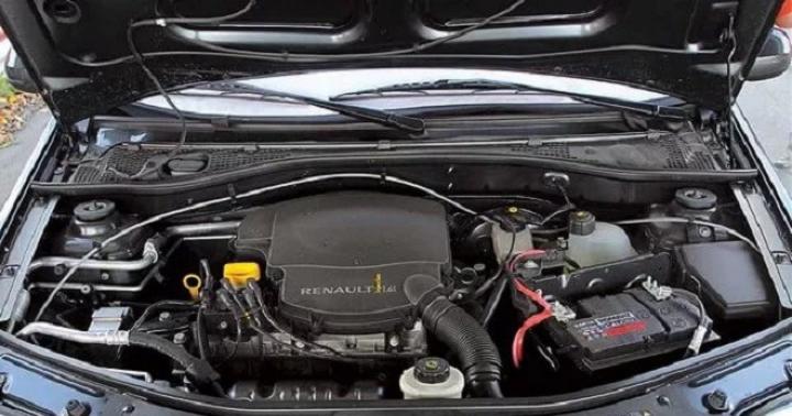
In the design, I used a two-stroke gasoline 13-horsepower motor of a cargo scooter "Ant" has a forced air cooling... This is an indisputable plus in a situation of inevitable overheating of the motor due to a low speed. The four-speed gearbox is interlocked with the engine, the muffler is homemade: a steel pipe filled with metal shavings (pipe length 250 mm, diameter 70 mm, exhaust outlet 16 mm). The exhaust tract has a complex shape due to the layout of the walk-behind tractor and the fact that the exhaust should be to the side.
The frame on which the engine is located is a sled, to the cross members of which an arc from a water pipe is welded (d = 42 mm). Brackets are welded to the arc in the center and at the ends.

Sub-frame
1 - slide runner (corner 40 × 40, 2 pcs.); 2- back cross member; 3 - ridge (steel pipe 1 1/4 ″); 4-bracket-bracket (StZ, strip 50 × 4, 3 pcs.); 5 - middle cross member: 6 - front cross member; 7 - traverse (corner 32 × 32); parts 2,5,6 are made of 40 × 4 steel strip
In place, through the holes in the ears on the engine crankcase, holes were drilled in the brackets for M8 bolts, after which the arc was installed with the center side and welded to the middle cross member of the sled, the extreme cross members were brought under the arc, bent, and their middle was also driven out in place so that the crossbars are in contact with the arc along their entire width. The arc was then attached to the cross members by welding along the tangency lines, and the ends of the cross members were welded to a guide rail made of an equal 40 mm steel angle.

Motor dimensions and mounting points
A bolt hole is drilled in the center of the vertical flange of the traverse, welded from above to the front ends of the rails. The bolt (M10) is also included in the front cross member of the frame and is designed to adjust the chain tension from the 1st gear stage. The skids move along the side members in the longitudinal grooves (there are four of them, two in each runner). The subframe is attached to the main frame through the slots with four M10 bolts.
Chain reducer
The two-stage chain reducer is designed to reduce the rotational speed and increase the torque transmitted from the output shaft of the power unit to the wheels or rippers.

Chain reducer drawing
1 - case (channel No. 20); 2 - cover (StZ, sheet s5); 3 - gasket (oil-resistant rubber) 4 - second stage drive sprocket (z = 11, t = 19.05); 5-key; 6 - bearing 206 (2 pcs.); 7- compensation sleeve; 8 - shaft; 9 - nut М22х1.5 with a spring washer; 10 - stuffing box; 11 - distance sleeve with keyway; 12-eccentric bearing housing (StZ, 2 pcs.); 13 - screw M8 with a spring washer (30 pcs.); 14 - driven sprocket of the second stage (z = 25, t = 19.05); 15- bearing 3008 (2 pcs.); 16 - bearing housing; 17 - sealing sleeve; 18 - left semiaxis; 19-oil drain plug (screw M10); 20 - the bottom of the case (StZ, sheet s4); 21 - oil filler plug (screw Ml0); 22.23 - oil seals (2 pcs.); 24 - right semiaxis; 25 - fixing screws M6 (8 pcs.); 26 - bolt М8; 27 - chain t = 19.05; 28 - driven sprocket of the first stage (z = 57, t = 12.7); 29 - distance sleeve
The 1st gear stage consists of two sprockets (17 and 57 teeth with a pitch of 12.75 mm). The driving sprocket (17 teeth) is mounted on the output shaft of the power unit, the driven sprocket is mounted on the outer flange input shaft 2nd stage. 2nd stage of the gearbox - reinforced (driving sprocket with 11 teeth, driven by 25, tooth pitch 19.05 mm). Since this step during the operation of the walk-behind tractor is close to the cultivated soil, to protect it from dust, it is placed in a closed crankcase, welded to the crossbars directly and to the side members through steel spacers.
A brace is welded between the crankcase and the cross member, for reliability. The crankcase is welded from two channels No. 2 with shelves reduced in length to 35 mm. In the lower part, the shape of the walls of the channels is a semicircle, instead of the shelves that are cut off, the bottom is welded from a 4-mm steel sheet bent in the form of a half-cylinder along the walls of the channels. The top of the crankcase is covered by a cover with an oil-resistant rubber gasket.
In both walls there are two coaxial holes for the bearing housings (d = 100 mm). Each of these holes is lined with six other threaded holes (M8) for attaching the housings to the crankcase. The lower bearings (that is, semi-axle bearings) have conventional housings, the upper (shaft bearings) have eccentric housings. By turning them around the axis (at least 15 °), the chain tension of the 2nd gear stage is adjusted stepwise.
The shaft of this gear stage is installed in two ball bearings 206. The drive sprocket is fixed by two spacer sleeves between the inner walls of the crankcase, exactly in the middle, and is connected to the shaft by a parallel key. The large driven sprocket sits on the centering boss of the right axle shaft and is secured with six M8 bolts between the counter flanges of the axle shafts. Its lower teeth, together with the chain links on them, are constantly immersed in oil. During the operation of the walk-behind tractor, oil is transferred by a chain to the upper part of the crankcase, thus, rubbing parts of the 2nd stage are lubricated. Stuffing boxes in the bearing housings protect against oil leakage to the outside. The axle shafts are rigidly flanged to form a single shaft that is housed in two 308 ball bearings.
Homemade wheels
Through the splines at the ends of the axle shafts, the torque is transmitted to the rippers or to the wheels. Rippers - homemade, wheels with 5-10 ″ tires borrowed from motorized carriages SMZ... To improve grip in winter or when cultivating the soil, a self-made 90 x 5 mm steel strip bandage with lugs from an equal 25 mm corner is put on the tires.

Homemade lugs
Dismountable bandage with lugs: 1 - band half-ring (steel strip 60 × 5.2 pcs.); 2 - hinge loop; 3 - locking lug; 4 - transverse lug (corner 25 × 25, 11 pcs.); 5 - diagonal lug (corner shelf, 12 pcs.); 6 - bolt М8 of the locking device (2 pcs.); 7 - mating half of the locking device (corner 25 × 25)
The tendrils on the lugs with parts of the vertical shelves cut off on their sides prevent the bandage from sliding off the tire. The antennae are bent inside the bandage hoop, and the cut-off parts of the shelves are welded to the hoop obliquely between the corners. The bandage hoop is composite: its two halves are connected by a hinge on one side and a locking device on the other (a similar locking device is used on the gearbox housing cover). It is convenient to mount such a hoop on tires.
The cultivators (one, two or three legs) are mounted on a T-shaped subframe made of rectangular 60 x 40 mm tube. The traverse can be detached. These parts are prefabricated, they were picked up at a landfill for agricultural machinery. In the front part of the subframe, a coupling device from channel No. 6.5 is fastened by welding.

Cultivator subframe
1 - traverse; 2 - bracket (2 pcs.); 3 - M12 bolt (3 pcs.); 4 - traverse mounting flange (corner 30 × 30.2 pcs.); 5 - bolt М8 (4 tt.); 6 - ridge; 7 - coupling device (channel No. 6.5); 8- M8 bolt for attaching the subframe (2 pcs.); 9- mating part of the coupling device (milled channel No. 8: the size between the shelves is 65 mm); 10 - an earring for connecting the trolley; 11 - gearbox housing; 12 - pivot (pipe with a diameter of 22 with M22 thread and M22 nut); parts 1, 2, 6 are made of steel rectangular pipe 60 × 40; a - three rectangular holes for the racks of the cultivator paws (dimensions in place)
For connection, the subframe is inserted into the bracket on the frame (gearbox housing). Bracket material - channel No. 8 with shelves, milled so that there is 66 mm between them. The subframe and bracket are connected with M8 bolts.
It was necessary to abandon the use of a walk-behind tractor in tandem with a one-piece plow (also home-made), since it was difficult to work with such a set, and the business progressed slowly. The role of a home-made plow for soil cultivation is performed by two rippers (two cutters, that is, several knives with cutters), installed in place of the wheels.

Rippers
Ripper assembly elements: a - splined sleeve with four flanges and end washer; b - knife with a cutter (16 pcs.)
The cutters are fixed with M8 bolts on the flanges, which are pushed onto the sleeve and welded to it. The diameter of the spline part of the semiaxis is slightly less than the diameter of the sleeve. The material of the knives is a steel strip of 50 x 60 mm, the cutters are from a decommissioned mower. For loosening the soil, one or two legs are installed in the cultivator stretcher, creating a braking torque. In this case, the rippers slip when rotating, go deeper into the soil and finely crush it. The braking torque can be adjusted with a different number of legs and a different degree of their depth. If it is adjusted, the walk-behind tractor moves evenly forward by itself and is easy to operate. When processing ups and downs, you will have to adjust the braking torque manually, with the effort on the steering wheel, deeper or shallower immersing the blades into the soil. The depth of cultivation with rippers, like a conventional shovel, is about 20 centimeters. After loosening, the soil is soft, level and does not need to be harrowed.
Homemade trailer
As mentioned above, the walk-behind tractor can be converted into vehicle for cargo transportation, with a two-wheeled semi-trailed trolley. It turned out to be very simple to make a trailer for a walk-behind tractor with your own hands. Chassis carts - front axle SMZ motorized carriages assembled (with wheels). The main frame consists of two spars with two cross members made of steel pipe, the cross section of which is a rectangle of 60 x 30 mm. In the front, where the side members converge, the seat is located.
The drawbar of the bogie is stepped so that the coupling device is closer to the axle of the wheels. As a result, handling is as easy as for articulated frame designs. Half-inch pipe struts are designed to reinforce the drawbar steps. Steps are welded to it from below. The design of the hitch is relatively simple: like a swivel, so that you can turn on uneven roads or slopes, relative to the horizontal longitudinal axis.
At the top of the main frame is a frame flanking the cargo platform made of an equal 35 mm steel angle. To strengthen the structure, additional connections have been created: the bogie frame is connected to the bridge levers through struts reinforced with struts (struts made of the same pipe as the frame). The frame-edging of the platform is lined with a tongue-and-groove board 25 mm thick. In further author's developments, removable or folding sides are provided.
The electrical equipment of the walk-behind tractor is designed for a voltage of 12 V: a standard ignition coil, two 9MT-14 batteries, a starter, a 90 W generator, and a car headlight.
It is not an easy task to process a plot with a large area, in which a significant part of the territory is allocated for a vegetable garden, using only improvised tools. Loosening, digging, and weeding the garden by hand takes a lot of time and effort. It's good when there is an opportunity to purchase a walk-behind tractor, which will become an indispensable assistant on the site. But you can make it easier to work on the ground by making a walk-behind tractor with your own hands.
We build a walk-behind tractor according to the instructions from Arkhipov
The device of the walk-behind tractor is a self-propelled car on two wheels, equipped with an engine removed from the VP-150M scooter. The reason for choosing this particular engine was that it has such a design solution, thanks to which the forced cooling of the cylinder head with air is carried out.

Such a motor from a scooter is capable of operating at lowest speeds at fairly heavy loads

For the construction of the walk-behind tractor, the master used control cables, engine mounts, and also a double arc of the frame, handle and chain taken from the scooter. The rest of the construction details were manufactured
Separately, the designer made a U-shaped frame welded from pipes and a wheel axle turned on a lathe. He also made 3 homemade hinges for the main and control rods. They will be used as connecting elements between the walk-behind tractor itself, its steering wheel and the plow.
A steel pipe is attached to the frame of the unit by welding, ending with an axle, which is necessary to tension the cables going to the engine gearbox. The tension itself is carried out by means of a swinging rocker arm, the gear lever of which is a welded piece of steel pipe.
The pitch of the chains used to create the device is 12.7 mm and 15.9 mm. The number of teeth in the sprockets: output shaft - 11, output shaft - 20 and 60, travel axle - 40.
Why is this particular design good?
There are more than a dozen analogs of such a model, but in comparison with them, the original model of the Kaluga master walk-behind tractor has a number of indisputable advantages.
- Swivel connection. Most of these machines are rigidly coupled with working tools and tractors, which makes it difficult to maneuver the machine and thus make it difficult to work with it. The details of this agricultural unit are connected by means of hinges. This makes it possible to change the direction of movement during work, if necessary, without removing the plow from the furrow.
- Offset of the axis to the direction of travel. Many owners, when cultivating the soil with the use of a walk-behind tractor, faced such a difficulty that in the process of moving forward under the influence of soil resistance, the unit is pulled to the side. A lot of effort should be made to align the furrow. To compensate for such a skid, the foreman positioned the plow axis at a slight angle towards the direction of travel. When plowing, the structure is slightly turned to the left. The desired position can always be adjusted with the three link pivots.
- Level of the set plowing depth. If in other models the plowing depth is maintained by lowering or raising the plow, then when working with this walk-behind tractor, it is performed automatically. Regulation is carried out by changing the angle of the plow in relation to the furrow. The structure is equipped with a field board, which acts as a lifting force when the plow is buried. If, on the contrary, a ploughshare appears above the surface of the earth, then its angle of attack instantly increases, under the action of which it again plunges into the ground to a given depth.
Step-by-step device assembly technology
The assembly of the structure begins with the arrangement of the running shaft. To do this, a housing with bearings is attached to it, an asterisk is welded on and overrunning clutches are mounted, which will perform the function of a differential during operation. After that, the structure is equipped with wheels and a frame. A telescopic rod, a plow and a steering wheel are installed on the fixed frame.

The main elements of the travel shaft: 1 - shaft, 2 - sprocket, 3 - cover, 4 - bearing housing, 5 - support platform, 6 - bearing No. 308, 7 - overrunning clutch housing, 8 - dog axle, 9 - dog, 10 - ratchet, 11 - bearing No. 307, 12 - washers, 13 - wheel, 14 - pawl spring
An agricultural walk-behind tractor is equipped with special wheels, which, unlike rubber counterparts, are capable of providing better grip on the ground.

These metal wheels are not clogged with earth. When in contact with the ground, they do not compact it, but rather loosen it
To connect the frame of the unit with the engine mount and the frame of the scooter itself, two arcuate pipes are used. A place is provided between them for placing a fuel tank.
To equip the engine, a bracket is used, ending with a steel axle with a length of 150 mm. The bracket is welded cantilever to the U-shaped frame of the structure. A motor with a suspension is suspended on the axle itself. The assembled structure is connected to the arched arches of the frame. Only after that the secondary shaft is mounted, the control cables are pulled and the chains are tensioned.

The main elements of the control unit: 1 - connecting axle, 2 - strip, 3 - pipe, 4 - handles

Connecting elements of the structure: 1 - main rod, 2 - control rod
How this whole thing works - video example
An illustrative example of the use of a walk-behind tractor:
How can you upgrade a homemade walk-behind tractor?
The Arkhipov walk-behind tractor is multifunctional. It can be used as a plow, or else. To do this, it is sufficient to replace the detachable parts for the plow with parts with the cultivator blades removed. The walk-behind tractor will deepen the furrows into the ground and place potato tubers in them. To plow the tubers, you just need to put the dumps in place and walk the unit between the planted rows.
The agricultural unit is also convenient for harvesting. Using different plows, you can change the working width. The unit is also good in that it is able to collect missed potatoes and tops of plants left after harvesting. For these purposes, it is equipped with a rake or harrow.
The universal design can be used not only for agricultural work. In winter, it is successfully used to remove snow. A faithful assistant will also come in handy for cleaning the paths of the local area. By installing a roller with a round brush and an additional sprocket on the walk-behind tractor, the owner will make it easier for himself to clean the sidewalks.
If you decide to make a home-made walk-behind tractor from a motorcycle engine, the main condition is to make the most of the exhausted units of motor vehicles, minimally altering them. This will require some experience and accumulated knowledge, with a large supply of patience and work. The result of this work will be a reliable farm machine, adapted to almost any conditions. If a malfunction occurs, the repair will be the replacement of a broken part, or a failed assembly.
For example, if you take a sub-frame or power unit: they are made in production. If we consider the reducer-adapter, it is taken from the main gear of the motorized carriage.
We make a homemade walk-behind tractor from a motorcycle engine
For the successful operation of the walk-behind tractor, a multi-stage kinematic transmission scheme was developed, which increases the relative ratio, as well as tractive effort and torque. Together with a reducer adapter, a main reducer is provided in the kinematic diagram. When combining a gearbox with a wheelset and a main drive, a highly efficient propulsion device is obtained.


A special mechanism tightens the drive chains. It is attached with pins to the sliders, which are made of steel angle. The latter are also able to move by tightening or loosening the drive chain. For this purpose, grooves are provided in the sliders and there are two adjusting screws and M10 fastening bolts.

The most labor-intensive design is the main gearbox. It is made from pre-prepared steel plates (10 mm). Reinforcement discs are placed in the place where the bearings are installed. The welds are solid to prevent oil leakage. A bracket-bracket is welded to the rear wall of the gearbox, which allows you to attach a cargo trolley or a trailed agricultural implement. If you use a cargo cart, then the walk-behind tractor becomes a mini-tractor.

A steel plate (5 mm) is used for the manufacture of the gear cover. It is attached to the body with M6 screws. Cylindrical spur gears and shafts are taken from agricultural machinery. It must be remembered that the purpose of the intermediate shaft is to take off power, so it is better to make new shafts than to use old ones. The differential of the main gearbox on the walk-behind tractor was part of a decommissioned electric car.
Locking the wheels of a walk-behind tractor with an engine from a motorcycle
Wheel blocking is a necessary technical solution for a walk-behind tractor, from a design point of view. On the right axle shaft, where the spline end is, a cylindrical neck is machined, which should be slightly deeper than the spline groove. A threaded hole is made from the opposite end of the semiaxis.

When the M12 adjusting screw rotates, the axle shaft is displaced due to the action of the coil spring. Further, inside the differential, the axle shaft moves away from the engagement with the "native" gear and engages with the adjacent one, which blocks the wheels.
The impellers of the walk-behind tractor are made from the wheels of a decommissioned electric car. Each disc, in the rim, has 16 grooves cut through, and steel plates are welded in, which will serve as the basis for the lugs. After that, jumpers are welded to them, and the rims of arable wheels are obtained.

Walk-behind tractor plow
The knot that regulates the entry of the plow into the soil has been made very efficiently. It consists of a welded U-shaped body, with mounting and limiting protrusions. A plow gradient heel is inserted into them, which is able to rotate in a vertical plane using a sleeve-axial joint. The required angle of rotation is set by the M16 pin. A beam channel is welded to the swivel heel. Thanks to a slight turn to the side where the soil falls off the plow, it becomes possible correct installation the latter.

The cut-off knife is also attached to the beam. In order to install it at the desired angle to the soil and at the required value, a typical clamp with a plate-plate and two M12 bolts with nuts are used. In front of the walk-behind tractor, an auxiliary wheel is located on a V-shaped bracket. Its purpose is to ensure ease during transportation, or when moving the walk-behind tractor.
The walk-behind tractor is controlled by means of two rods from the mower with handles. Also for this, the reverse and speed shift knobs are used.

The productivity of the walk-behind tractor is three to five hundred square meters of land per hour. Ordinary soil can be plowed in second gear. For heavy soils, work first.
How to make a walk-behind tractor with your own hands from the engine of the planet
The scheme for creating this walk-behind tractor is perfect for Voskhod, Minsk, Muravei engines. Best of all, the engine from IZH Planet-3 has proven itself. To make a walk-behind tractor with your own hands from the planet's engine, you need to make small design changes.

Cooling of the engine is forced, connected through the ignition - to the coil. Engine power 18 HP Thanks to the installed gearbox, there is a reverse gear.

Transport speed - up to 70 km / h. The minimum speed is 5-6 km / h. The trolley is made of two old tarsion type strollers, and can bear a weight of up to 500 kg.

The frame is welded to the channel. When modeling a walk-behind tractor, it is necessary to take into account the fastening of the engine, therefore, we displace the longitudinal axis of the gearbox by 10 mm, relative to the axis of the engine. The engine can be mounted in different ways. To increase the engine power, an additional shaft is cut into the channel.
After that we place fuel tank... Upon completion of the assembly, we give the walk-behind tractor a beautiful appearance by painting.

This walk-behind tractor is capable of driving 50-70 km per day. On the asphalt, you can keep the speed of 50-60 km / h. It can be used as a vehicle and as a walk-behind tractor.
DIY motoblock from a motorcycle video selection
When self-designing a walk-behind tractor, the basis was taken old motorcycle"Minsk", which had been in the garage for a long time and did not find any practical application. And continuing the topic "", let's talk about how to make a walk-behind tractor from a Minsk motorcycle.
The main task was to make agricultural machinery with our own hands, at home, without buying expensive parts and elements and without the need to use lathes and other machines. Well, and most importantly, the walk-behind tractor should be convenient for agricultural work and become an assistant in work in the fields - plowing, hilling, collecting and transporting crops.
The walk-behind tractor turned out to be just that - multifunctional, convenient, which has been repeatedly confirmed by field tests. The equipment accepted the rather difficult and difficult working conditions perfectly and behaved with dignity.
How it all began - a walk-behind tractor from Minsk
The beginning of the work was the alteration of the motorcycle frame and its adaptation to our requirements. Unnecessary footrests and other details have been removed. Only part of the driver's footboard on the right side remained, later it served as a support for exhaust pipe walk-behind tractor. The seatpost was also removed, but only after the handlebars were welded to the frame from a 1.25-section tube, made as one element (curved) together with the spacer, levers of a shape suitable for controlling the technique.
Particularly careful attention was paid to the manufacture of a sleeve designed for the drive shaft of the wheels and its installation on the frame of the future walk-behind tractor. If there was such an opportunity, then it would be much better to manufacture it on a lathe from round bars or thick-walled pipes, but this type of equipment was not available, then the sleeve was made from pipe sections without a seam suitable sizes by welding. Also, by the way, a bushing was made for the intermediate shaft.
Large diameter pipe pieces served as ball bearing seats. Bearings were used type 80205. Type 60205 could also be taken with a washer from various contaminants (if you use such bearings, then the washer must certainly be turned to the outside.)
Under the downtube of the motorcycle frame, a place was set aside for attaching the wheel hub - an arched opening. For correctness, this sleeve must be attached with great accuracy perpendicular to the diametrical plane of the available frame. Which was done with all diligence.
All the nodes of the resulting walk-behind tractor can be seen in the drawing below.
Motoblock from an old motorcycle (units and assemblies pos. 6,8,9,10,13-from the motorcycle "Minsk"):
The rather simple design of the equipment makes it reliable and convenient.
Land plots in villages and large summer cottages require colossal labor costs during the period of plowing, hilling and cultivation. The task can be greatly facilitated with the help of a tractor, but its cost for many small farmers and gardeners is prohibitively high. An excellent solution in this case would be to assemble a homemade walk-behind tractor from a chainsaw or motorcycle.
Application area
The advantage of the walk-behind tractor lies not only in its low cost, but also in its increased maneuverability, which allows work to be carried out in areas where the tractor simply cannot pass in size. It can handle plots as small as one square meter.
Depending on the installed additional equipment, the walk-behind tractor is used to carry out certain types of work on the land. Lightweight models are usually equipped with a weeding tool and a milling cutter. Heavier specimens can already be used for plowing, hilling and mowing.
On a heavy walk-behind tractor installation of the following devices is allowed:

With the help of such a device, if you add a seat and a trailer to it, you can transport various loads weighing up to 300 kg over short distances. It is actively used for planting and collecting potatoes and other crops. The walk-behind tractor acts as an irreplaceable assistant when cleaning large areas from snow, drilling and fertilizing the soil.
DIY unit design
Despite the fact that the cost of such a device is many times less than a full-fledged tractor, not every summer resident or villager can afford to buy a factory-assembled walk-behind tractor. Prices for branded products range from 30 to 200 thousand rubles. The cheapest are units made in China, the reliability of which is highly questionable.
Assembling a homemade walk-behind tractor with your own hands is a profitable option. The required costs, in the presence of most of the spare parts, which are usually always available in private households, will be minimal, and the quality is no worse than the factory one.
Necessary components
Before starting assembly work, you should decide what rated power the homemade walk-behind tractor will have. Most the best option- use the IZH Planet 5 motorcycle or a powerful chainsaw, for example, "Ural", as a spare parts donor. But you can use any similar engine.
To assemble a homemade walk-behind tractor you will need:
- blueprints;
- welding machine;
- set of tools;
- steel pipes;
- car wheels or sheet metal;
- donor (motorcycle or chainsaw).
In the process of carrying out the work, additional parts will be required to connect the engine and frame. Attachments can be used from the factory or can also be made independently from improvised means.
Frame making
Since in each case, the design of the unit may differ depending on the parts used and the engine, before starting the assembly, you need to draw up a work plan and make the necessary design drawings, relying on the operating manual of the factory walk-behind tractor.
General principles and the procedure for the manufacture of the supporting structure is as follows:

In addition, you can use a ready-made motorcycle frame, slightly modifying it. You will need to remove the front fork and any parts that interfere with the installation of new equipment. Behind it, a hitch mount should be welded.
With this option, they usually immediately install the wheels from the car, adding an axle made of solid round timber to the design.
Power unit creation
 Regardless of, motorcycle engine installed on a walk-behind tractor, from a scooter or a chainsaw, all of them must have active air cooling. To facilitate starting, it is required to change the power system by replacing the fuel supply valve with a petal.
Muffler use motorcycle or they make it independently from a pipe with a diameter of 70 mm. To do this, you need to cut off a small part about 25 cm long from it, fill it with sawdust and shavings. The outlet must be narrowed in half.
The muffler should be located so as to completely ensure the removal of exhaust gases away from the person who will operate the walk-behind tractor. A separate steel structure is assembled for the engine from pipes with a diameter of 42 mm. Outwardly, it should resemble a sled with brackets that have holes for bolts with which it is attached to the main frame.
Main nodes
In addition to wheels, an engine and a frame, a multifunctional walk-behind tractor must be equipped with additional units, without which it is impossible to perform a number of basic tasks, and its use will be limited simple transportation of goods.

The travel reducer is a gearbox element that makes possible work machine at the lowest speed. In factory models, the travel reducer is installed on the gearbox, respectively, this must be done on a home-made walk-behind tractor. When planting or harvesting potatoes, sowing or plowing the land from power plant maximum power is required at the lowest rpm. You won't be able to achieve this effect without installing this node.
A gearbox is a mechanism that transfers engine torque to individual units that drive the walk-behind tractor. Install it between the wheels of the unit and the engine.
When working with some additional equipment the transmission of torque occurs directly to it. If a drill, cutter, snow blower or tracks are installed, the gearbox starts working directly with them. Without appropriate experience and knowledge, you should not try to assemble and install this unit on your own: it is better to purchase it in a store or remove it from old equipment.
Attachments
 A motoblock is a multifunctional unit and, in addition to processing a land plot, it is actively used when cleaning territories, transporting goods and mowing grass. With the help of the bracket mounted on the rear of the frame, the following are attached to it: plow, harrow, rake, milling cutter, digger, bulldozer knife, rollers, brushes and other devices.
Many models, including home-made ones, are equipped only with a steering wheel. In this case, a person walks behind the walk-behind tractor in the process of performing work. However, if necessary, an adapter can be made that will allow the unit to be operated while seated.
For the adapter you will need:
- steel sheet;
- seat;
- a pair of wheels;
- pipe;
- coupling;
- tools and welding machine.
At the end of a rectangular pipe, 1.7 m long and 6 cm wide, 4 cm high, you need to weld a half-meter pipe on which the wheel racks will be located. The height of these racks from the attachment to the center of the axis is 35 cm ... The seat can be of any design, but should not exceed 45 × 45 cm.
After assembling and installing the wheels, the control is attached to the frame attachments and connect the structure with the walk-behind tractor using a hitch.
Homemade trailer
The trailer can be manufactured in several ways and using different materials. As a rule, homemade structures are made from a metal frame and wood.
Procedure:

The tailgate of the trailer is hinged to facilitate loading and unloading. Metal amplifiers are welded on the sides. The trailer is painted and connected to the walk-behind tractor.