The vibration type works on voltage deviation. The principle of operation of the vibration-type voltage regulator is based on the inclusion of an additional resistor in the excitation winding circuit of the generator when the voltage at the generator terminals increases (Fig. 1).
The regulator consists of an electromagnet Y, an armature with a movable contact S, a fixed contact and an additional resistor R1 included in the LG excitation winding circuit of the generator.
At normal voltage the contacts are closed, and excitation winding generator receives power from the armature, bypassing the resistor. As soon as the voltage at the generator terminals increases, the electromagnet Y, overcoming the resistance of the spring P, will attract the armature and open the contact. As a result, the current into the field winding will flow through an additional resistor, and the voltage at the generator terminals will decrease.
Rice. 1. The principle of operation of the vibration-type voltage regulator
This will cause a decrease in the current in the coil of the electromagnet Y, the contact will close, the additional resistor will be turned off. The excitation winding will be turned on at full voltage, the current in it will increase, and the generator voltage will increase. The switching on and off of the additional resistor in the generator field winding circuit occurs at a frequency of 20 - 30 times per second, which, in the presence of the field winding inductance, makes the voltage fluctuations in the network almost imperceptible. The average value of the duration of the on state of the contact S relative to the off will determine the average value of the excitation current, and therefore,.
Thus, the generator voltage regulation limits are set by the on and off state of the contact S. The value of the duration of the on state of the contact is regulated by the tension of the spring P.
A large number of small-displacement vessels, including hydrofoils, have a voltage of 24 V. Electricity sources are low-power generators (1200 or 1500 W), mounted on a diesel engine, etc. On ships of small displacement, G-732 generators with a vibration-type relay-regulator RRT-32 and GSK-1500 generators with a vibration-type relay-regulator RK-1500 are most often used.
In fig. 2 shows a diagram of a relay-regulator RRT-32, complete with five electromagnetic devices: a reverse current relay K1, two current limiters K2, K3 and two voltage regulators K4, K5.

Rice. 2. Schematic diagram relay-regulator RRT-32
Current limiters (contacts K2.1, K3.1) and voltage regulators (contacts K4.1, K5.1) operate on the principle of vibration regulators. Contact K1.1 ensures the operation of the reverse current relay. Winding 1-12 are the control windings of the regulator relay.
Vibration voltage regulators of generators (Fig. 3, a) are used on dredgers. The main element of such a regulator is an electromagnet, the principle of which is illustrated in Fig. 3, b. F1, created by winding L1, depends on the voltage of the generator; flux Ф3 is created by winding L3, connected in series with the excitation winding of the generator; flux F2 is created by the L2 winding connected in parallel with the generator excitation winding.
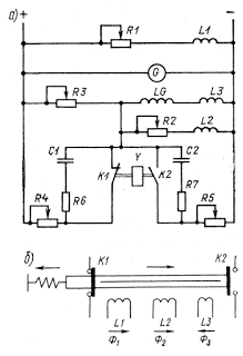
Rice. 3. Schematic diagram of vibration
generator voltage regulator direct current
When the regulator is operating, depending on the effect of the electromagnet windings, the core can occupy an intermediate position, then the contacts K1 and K2 will be open, or any extreme position, then the contact K1 or K2 will be closed. The total magnetic flux of an electromagnet depends on the generator voltage and the effect of temperature on the elements of the excitation system.
Instead of vibration regulators for ship generators, contactless relay regulators(fig. 4).
Their action is as follows. As the voltage at the generator terminals increases, the excitation current will increase, since at a voltage lower than the nominal, V1 does not pass current and the base potential of V2 becomes higher than the emitter potential - the V2 transistor is closed. With the closed transistor V2, the voltage at the base of the transistor V3 is lower than the potential of its emitter, therefore the transistor V3 is open, and current flows in the excitation winding of the generator.

Rice. 4. Schematic diagram of a contactless voltage regulator
As soon as the voltage at the generator terminals exceeds the nominal value, the Zener diode VI will pass the current, the voltage drop across the resistor R4 will exceed the voltage drop across V4, and the V2 transistor will open; in this case, the potential of the transistor V3 will become higher than the potential of the emitter, and the transistor V3 will close. The excitation current as well as the generator voltage will decrease. The voltage drop will continue until the Zener diode V1 closes. After that, the transistor V2 will close, and the transistor V3 will open, and the whole cycle will repeat.
The use of diode V4 as a feedback element degrades, especially with a pre-connected load, when the threshold resistance of the diode is higher than the critical resistance of the generator excitation circuit. To improve the conditions for self-excitation of the generator, it is recommended to shunt diode V4 with resistor R3.
The generator current is limited by the V5 transistor. At rated current, the voltage across the diode V6 exceeds the voltage across the resistor R8, so the base potential of the transistor V5 is higher than the emitter potential, and the transistor is off. If the generator current becomes more than the rated one, the voltage across the resistor R8 exceeds the voltage across the diode V6, the V5 transistor will open, as a result of which the base potential of the V3 transistor will rise above the emitter potential, and the V3 transistor will close, the excitation current will stop, and the generator voltage will decrease, reducing the load current.
The reverse current is limited by the diode V7, which passes current to one side and turns off when a voltage of reverse polarity is applied to it.
The voltage regulator serves to automatically maintain the generator voltage within the specified limits when changing the rotor speed and the generator current in load mode, as well as when the ambient temperature changes. The value of the maintained voltage is selected taking into account the provision of charge battery and the normal operation of lighting products.
The voltage regulator 201.3702 is installed on the ZIL-431410 car, the RR132 regulator on the ZIL-133GYa car, the RR132-A regulator on the ZIL-131N car, and the Y112-A regulator on the ZIL-435850 car.
Voltage regulator 201.3702 is designed to work with generators G250 I1 and 32.3701 (6.6). The regulator is a contactless relay based on silicon semiconductor devices.
The regulated voltage level of the 201.3702 regulator with a connected battery at the generator rotor speed (3000 ± 150) min "1 and the load current (14 +1) A for the G250 I1 generator and (20 ± 1) A for the 32.3701 generator is 13 , 8 ... 14.5 V, and the 201.3702 regulator (tropical version) 13.3 ... 14.0 V.
The regulator includes the following functional blocks and elements:
a measuring unit designed to compare the actual voltage with the specified one. The measuring unit includes a transistor VT1, a Zener diode VD1, a capacitor C1 and resistors R1 ... R7;
a regulating unit serving to amplify the signals of the measuring unit and regulate the excitation current of the generator. It includes a control element consisting of a transistor VT3 and resistors R10 ... R13; an output transistor switch made on a composite transistor (transistors VT4, VT5), resistors R14, R15 and a quenching diode VD3;
a short-circuit protection unit of the "shunt" to "-", consisting of a transistor VT2, a resistor R9, a capacitor C2 and a diode VD2. Resistor R6 provides a common negative link and resistor R8 provides a local positive link;
diode VD4, designed to protect semiconductor elements from voltage pulses of reverse polarity.
The regulator works as follows. When the engine is not running, the voltage at the regulator terminals "+" and "-" is equal to the battery voltage and is not enough to open the measuring transistor VT1, the emitter of which is connected to the Zener diode VD1, which acts as a reference voltage source. The control transistor VT3 is closed, and the composite transistor VT4, VT5 is open. In the circuit of the excitation winding of the generator, a direct current flows, the strength of which. rogo is limited by the active resistance of the excitation winding and the voltage drop across the emitter-collector junction of the saturated transistor VT5. At the same time, transistors VT4, VT5 open under the action of the current flowing through the circuit: "+" of the battery, current indicator, switch S2, "+" of the regulator, emitter - base of transistor VT5, emitter-base of transistor VT4, resistor R14, resistor R13, resistor R12, terminal "-" of the regulator, car body, "-" of the battery. In this case, the potential difference on the plates of the capacitor C2 is close to zero, there is no current in its circuit, as a result of which the VT2 protection transistor from a short circuit of the W terminal to the case is closed.
When the engine is started and the generator rotor speed rises, the voltage level at the terminals "- (-" and "-" of the generator set begins to increase. In this case, the voltage applied to the input divider (resistors Rl, R2, R3, R4) increases. Accordingly, the voltage at the base of the transistor VT1 increases and when a value is reached sufficient to unlock it, the transistor VT1 opens and, accordingly, the transistor VT3 opens. The resistance at the collector-emitter transitions of the transistor VT3 decreases sharply, the transistors VT4 and VT5 close. At the same time, the current in the excitation circuit decreases, and consequently, the voltage in on-board network car. When the regulated voltage decreases to a value at which the current flowing through the input divider becomes insufficient to keep the measuring transistor VT1 open, the latter closes, and the control transistor VT3 goes into a closed state, and the transistors VT4 and VT5 open. The voltage at the terminals "+" and "-" of the regulator rises again. Further, the regulation process is repeated, as a result of which the voltage in the vehicle's on-board network is maintained at a predetermined level.
With periodic switching of the regulator circuit under normal operating conditions, the VT2 protection transistor performs the function of an element forcing the process of closing the VT4, VT5 transistors. When they are closed, the voltage at the terminals "-" and Ш increases, and a current flows in the capacitor-C2 circuit, opening the protection transistor VT2. Thanks to this, the process of opening the transistor VT3 and closing the transistors VT4, VT5 is significantly accelerated.
The opening of the composite transistor (VT4, VT5) is forced by connecting the capacitor C2, connected to the resistor R9 through the diode VD2, to the midpoint of the voltage divider R10, R11, connected between the base and the emitter of the control transistor VT3. When the composite transistor VT4, VT5 opens, the capacitor C2 begins to discharge along the circuit: diode VD2, resistor R11, emitter-collector junction of transistor UT5. In this case, a blocking voltage is applied to the base of the control transistor VT3 through the resistor R10, which provides a faster opening of the composite transistor VT4, VT5. Thanks to the forced switching of the VT5 power transistor, it was possible to significantly reduce the active power dissipated on it during the voltage regulation process in the vehicle's on-board network.
In the mode of short circuit of clamps Ш and "-" or short circuit in the excitation winding, the power transistor VT5 is protected from power overloads. Suppose that the short circuit occurred at the time when the control transistor VT3 is open and the transistor VT5 is closed. Due to a decrease in the voltage supplied to the regulator, the control transistor VT3 closes, and the power transistor VT5 opens. In this case, the collector current of the power transistor is limited by the inductance of the battery and the connecting wires of the regulator, then the transistor goes into a linear amplification mode, as a result of which the voltage at its emitter-collector junction begins to increase. In the circuit, the capacitor C2, the resistor R9, the base-emitter transition of the transistor VT2, a current arises that opens the transistors VT2 and VT3. This closes the power transistor. After charging the capacitor C2, the protection transistor VT2 and the control transistor VT3. close, and the power transistor VT5 opens. In this case, the capacitor C2 is discharged along the circuit: the diode VD2, the resistor R11 and the emitter-collector junction of the transistor VT5. The power transistor VT5 again goes into linear amplification mode. Thus, stable self-oscillations appear in the regulator circuit. In this mode, a pulse current flows through the power transistor VT5, the average value of which does not exceed 0.1 A, the active power dissipated by the transistor is no more than 0.5 W.
After elimination of the short circuit, the voltage regulator turns on automatically. This is due to the fact that after charging the capacitor C2, the power transistor VT5 does not go into the linear amplification mode, but remains in the saturation mode, which is why a current flows in the excitation winding circuit. The voltage at the terminals "+" and "-" of the generator will increase until the measuring transistor VT1 opens. Further, the above-described process of voltage regulation in the on-board network under normal operating conditions of the regulator takes place.
During the operation of the voltage regulator, it is not required to make any adjustments to it, therefore it is not recommended to open it. Failure of the regulator can occur due to improper operation or an open defect in the elements of its circuit. Repair of the voltage regulator should only be carried out by specialists and in specially equipped workshops.
The design of the 201.3702 voltage regulator ensures its interchangeability with the PP350 voltage regulator. The elements of the regulator circuit are mounted in a block consisting of a heat sink with a power transistor KT837X and a printed circuit board with the rest of the circuit elements, to which a three-pin connector is connected using flexible wiring. The block is housed in a metal case and covered with a steel cover. For installation on a car, the regulator body has two fastening legs with holes, one of which is equipped with an outlet for connecting the generator “-” clamp.
The PP132 voltage regulator consists of two main functional blocks: a measuring voltage divider (resistors Rl, R2, R7, a choke L), a Zener diode VD1, a transistor VT1 with resistors R3 and R5 and a regulating one - a transistor VT2, diodes VD2 and VD3, a resistor R4 ( 6.7).
The regulator works on the principle of a proximity relay. When the instrument switch is turned on, the voltage from the battery is supplied to the base circuit of the output transistor VT2 through the resistor R5 and the transistor will be open. A current flows through the excitation winding of the generator, the strength of which is determined by the battery voltage and the resistance of the excitation winding. This current provides excitation of the generator and an increase in the voltage at its terminals "+" and "-" as the rotor speed increases.
The resistance of the resistors of the divider is selected in such a way that when the engine is not running, the voltage drop across the Zener diode VD1 will be less than the stabilization voltage, and therefore the Zener diode breakdown in the opposite direction does not occur, the transistor VT1 is closed (there is no base current).
At a voltage of 13.5 ... 14.8 V, the zener diode breaks through, its resistance sharply decreases, and a voltage of positive polarity appears at the base of the transistor VT1. It is unlocked, and the transistor VT2 is locked due to a change in the polarity of the voltage at the base. At the same time, the resistance of the emitter-collector section of the transistor VT2, entering, increases sharply. into the field winding circuit, and, therefore, the generator voltage decreases.
The voltage decreases until the zener diode closes again. In this case, the transistor VT2 opens, and the generator voltage will increase until it reaches the set value and a repeated breakdown of the zener diode occurs. Self-oscillations are set in the system, due to which the set level of the regulated voltage is automatically maintained.
Resistor R7 is a trimmer and serves to regulate the voltage maintained by the regulator. The choke smooths out the ripple of the rectified voltage of the generator, since the peaks of the ripple voltage of the generator could cause false triggering of the elements. Diodes VD2 and VD3 serve to reliably block the transistor VT2. The VD4 diode shunts the self-induction EMF that occurs in the excitation winding of the generator when the current is switched in it, protecting the VT2 transistor from overvoltage. Feedback resistor R6 serves to increase the switching frequency and reduce the transition time of the circuit from one state to another.
In the case of the regulator, cast from an aluminum alloy, a printed circuit board is placed on which all the elements are located, except for transistors VT1 and VT2. The latter are mounted on an aluminum heat sink plate. A stand made of insulating material is installed between the printed circuit board and the heat sink plate.
Resistor R5 should have a resistance of 37.5 ohms and dissipate 6.5 watts. The dissipated power of MLT resistors is not more than 2 W. Therefore, to provide a power dissipation of 6.5 W, it is necessary to use four MLT resistors with a nominal resistance of 150 Ohm.
The cover of the regulator body is cast from an aluminum alloy, fixed to the body with screws. A rubber cord is routed between the body and the cover to prevent penetration
moisture and dust.
The regulator housing contains: “+” terminal with Mo ^ thread for connection to the “+” terminal of the regulator, W terminal with M4 thread for connecting the generator excitation winding and M5 threaded hole for connection to the car body.
The PP132-A voltage regulator works in conjunction with the G250P1, G287-B, 381.3701 and 382.3701 generators. The regulator is an improved modification of the PP132 regulator. It has a three-range adjustable voltage setting. Changing the voltage ranges is carried out by a switch located on the upper part of the regulator base (when the regulator is in the operating position - with the W pin down). The switch is closed with a plug. The position of the switch lever corresponds to the following values: leftmost - maximum, middle _ minimum, far right - middle. The voltage ranges are marked on the cover of the regulator. Regulators installed on cars have a medium range
settings.
The values of the regulated voltage at the ambient temperature and the regulator (20 + 5) ° С should be as follows: minimum (13.6 + 0.35) V, average - higher than the minimum by (0.6 + 0.15) V, maximum ( 14.7 + 0.35) B.
The operation of the regulator is checked at a generator rotor speed of 3500 min "1 and a current strength of 14 A for the G250Sh generator and 36 A for the G287-B generator.
The regulator circuit is shown in 6.8. The voltage divider of the regulator, in contrast to the PP132 regulator, has two additional resistors and a switch S3, which provides the ability to switch the ranges of the regulated voltage. Parallel connection of power transistors VT2 and VT3 increases the reliability of the regulator. Zener diodes VD2 ... VD4 are installed in the base circuit of these transistors. Their purpose is the same as the diodes of the PP132 regulator.
The rest of the circuit, the principle of operation and the design of the PP132 and PP132-A regulators are similar.
In the integral regulator Ya112A, a composite transistor VT2, VT3 is used, which made it possible to sharply reduce the power of other elements of the regulator (6.9). To reduce the power dissipated by the transistor VT3, a resistor R8 is included in its collector circuit. With an increase in the resistance of the resistor R8 to a certain value, the degree of saturation of the transistor VT3 increases and the power dissipated by it decreases.
The switching speed of the transistors in the regulator is increased with the help of feedback - a rigid emitter one by means of a resistor R7 and a flexible collector one formed by the C1-R9 circuit.
A capacitor is used as a filter in the regulator
C2, connected between the bases of transistors VT1 and VT2. At
supplying voltage from the battery through the switch
S1 ignition coil on the voltage divider circuit (resistors
Rl, R2, R3) current flows, and a drop is created across the resistor R3
voltage. Since the battery voltage is less
operation voltage of the transistor relay, transistor VT1
closed, the composite transistor is open. By winding excitation
current flows through the generator. With increasing speed
the generator rotor increases the voltage at the generator terminals. When the generator voltage reaches the value at which the transistor relay is triggered, the VT1 transistor opens and the composite transistor closes. The excitation winding of the generator is then disconnected from the voltage source. The emerging EMF of self-induction is closed through the shunt diode VD6. As a result, the excitation current and the generator voltage decrease. When the generator voltage drops to a value equal to the voltage of the return of the transistor relay to its original position, the transistor VT1 will close, and the composite transistor will open. Then the process is periodically repeated. The use of flexible feedback allows you to speed up the switching processes of transistors. When the composite transistor is in a saturation state, the voltage applied across the R9-C1 circuit is low (no current flows through this circuit). When the composite transistor switches from the saturation state to the cutoff state, the potential on its collector increases sharply and in the circuit resistor R9, capacitor C1, emitter junction of transistor VT1, a current pulse arises, forcing the switching process of transistor VT1, and, consequently, of the composite transistor. In this case, the capacitor C1 is charged. When the composite transistor transitions from the cutoff state to the saturation state, the capacitor C1 is discharged along the circuit resistor R9, the composite transistor, resistors R7, R4, creating a signal of reverse polarity at the emitter junction of the transistor VT1. As a result, the process of closing the transistor VT1 and opening the composite transistor is accelerated. The integral voltage regulator has a metal base 58x38 X 1.9 mm in size, which also performs the function of removing heat from active elements. Based on posted
a block of powerful active elements, which is a metallized ceramic substrate with open-frame transistors VT2, VT3 and diode VD6 soldered on it. The functions of a diode are performed by a transistor with short-circuited base and emitter electrodes. On the base there is also a block of low-power resistors, which is made in the form of a heat-conducting ceramic plate (substrate), on which resistors and conductors connecting them are applied by means of thick-film technology. Capacitors Cl, C2, a Zener diode VD4, a diode VD5 and a transistor VT1 are soldered to the contact pads of the resistor block.
A plastic cover is glued to the base of the voltage regulator, which protects the regulator elements from mechanical damage. To seal the voltage regulator elements, the free space under the cover is filled (through a hole in it) with a fuel-water-resistant compound.
The integral voltage regulator has a non-separable design and therefore cannot be repaired.
When replacing the Y112A voltage regulator or when installing a removed regulator, you must pay attention to the "technological key" on the base of the regulator, which is a protrusion with a width of 4 and a length of 2.6 mm. It provides an unambiguous setting of the voltage regulator to the generator.
The regulated voltage at a load current of 14 A, a generator rotor speed of 3500 min "1 and an ambient temperature (25 + 10) ° C of regulators in a version for a temperate climate is 14.4 V, in a tropical version 13.2 ... 13.9 V.
At each TO-2 check the cleanliness of the wire tips to the terminals of the voltage regulator and their tightness. During operation, voltage regulators do not require any adjustment. Therefore, it is not recommended to open them.
Regulator PP132-A allows changing the range of regulated voltage at CO. If it is necessary to change the range of the regulated voltage1, it is necessary to unscrew the cap covering the switch and switch the switch to the required position. When preparing the car for use in winter period the voltage is increased to fully charge the battery. After that, the plug is screwed in all the way, paying attention to the presence of a rubber O-ring.
Below are the main regulator malfunctions, their causes and solutions.
The driver, before leaving and during the operation of the car, checks the operation of the generator and voltage regulator according to the
the knowledge of the battery current indicator. The lack of charging current is a necessary, but not sufficient sign to conclude that the generator or voltage regulator is malfunctioning, since the battery can be fully charged and not take charge. Only the presence of a discharge current at an average speed crankshaft the engine indicates a failure of the generator set. In order for this sign to manifest itself more clearly, it is recommended to turn on consumers at an average crankshaft speed electrical energy(more convenient headlights).
The malfunction must be looked for in the generator (stator winding, rectifier unit), the connecting wire between the generator and the battery, or in the excitation circuit (excitation winding, brush assembly, voltage regulator, connecting wires from the ignition switch to the voltage regulator and from the voltage regulator to generator brush assembly).
In order to determine the faulty circuit, it is necessary to disconnect the wires from the brush assembly and apply voltage to the field winding directly from the battery. If a charging current appears when the engine is running, therefore, there is a malfunction in the excitation circuit (including the voltage regulator). In the absence of charging current, the generator is faulty.
A malfunctioning generator set is also indicated by a high charging current when the battery is charged. In this case, the malfunction is caused by the voltage regulator, which either does not regulate the voltage of the generator (it passes current into the excitation winding regardless of the rotor speed of the generator and its load mode) or is adjusted to a large value of the regulated voltage, which is accompanied by a rapid "boiling away" of the electrolyte in the battery during operating time.
When measuring the regulated voltage on a car, it is necessary to connect a voltmeter to the “+” terminal of the battery (“+” terminal of the voltage regulator) and the body; turn on (as a load) high beam headlights; fix the regulated voltage according to the voltmeter reading at the average engine speed.
To check the voltage regulator on a car, you can use the NIIAT-E-5 device. A more thorough check of the voltage regulator removed from the vehicle can be carried out at the mod bench. 532. In the absence of such a stand, the controller can be checked on a simple stand with a drive for rotating the generator rotor (6.10). When checking the regulator, it is necessary to set the generator rotor speed and load mode in accordance with technical characteristics regulator. In case of deviation of the regulated
voltage by ± 3% of the specified voltage regulator must be sent for repair.
In case of deviation of the regulated voltage, the regulator is regulated by replacing the tuning resistor in the voltage divider. In the voltage regulator 201.3702, the trimming resistor is the RJ resistor, in the PP132 regulator the resistor /? / And in the PP132-A regulator - the resistor R3. The integral regulator Ya112A is not regulated: the accuracy of regulation is ensured during the production process.
When repairing faulty voltage regulators, the main difficulties are associated with identifying faulty circuit elements. To do this, first determine the state of the output transistor (transistor VT5 for the 201.3702 regulator, transistor VT2 for the PP132 regulator and transistors VT2, VT3 for the PP132-A regulator). If the output transistor does not turn off when the voltage rises, then it is broken or always open. The output transistor is always open if: the zener diode does not work; the input (first) transistor does not open; the control transistor VT3 at the 201.3702 regulator does not open.
The zener diode does not work in the event of an open circuit in its circuit. The input transistor does not open when there is an open circuit in the Zener diode circuit and in the transistor circuit. The control transistor does not open in all of the above cases, as well as when its circuit is open. If the generator is not excited when the regulator is connected, then this means that the output transistor does not pass current, that is, it is always closed or there is an open circuit in its circuit.
The output transistor is always closed if the zener diode is broken or triggered when the generator voltage is low; the input transistor is open (or broken); open (or broken) control transistor at the regulator 201.3702
The elements of the voltage regulator circuit are checked, starting with the zener diode, for which at least one of its outputs is soldered off from the circuit and the resistance of the zener diode is measured with an ohmmeter, swapping the clamps on the terminals of the device under test. The zener diode is considered serviceable if, in one measurement, the resistance is no more than 100 ... 200 Ohm, and when the ohmmeter clamps are changed, it will be hundreds of kOhms. In a punched zener diode, the resistance is zero, and when the output is broken, it is infinite.
With a working zener diode, the state of the transistors is sequentially checked, starting with the input and ending with the output
To check the transistor, at least two of its terminals are unsoldered and an ohmmeter is connected alternately to any two terminals of the transistor. The transistor is considered serviceable if the resistance during these measurements is greater than zero, but not more than 500 kΩ and the ohmmeter has different resistances of the same transitions when the ohmmeter clamps are swapped. In a faulty transistor, the resistance between the two terminals is zero or infinity. If the zener diode and transistors are in good working order, use an ohmmeter to check the condition of the resistors and diodes included in the zener diode and transistors circuit.
Desoldering and soldering of semiconductor devices for testing and when replacing them is carried out with a constant heat dissipation between the body of the semiconductor device and the soldering point. It should be remembered that semiconductor devices are destroyed even when heated for a short time to temperatures above 150 ° C. Therefore, for soldering, you should use a solder with a melting point, as a rule, does not exceed 260 ° C (for example, POS-40 solder). The transistor base leads must be connected to the circuit first and disconnected last. Do not apply voltage to a transistor whose base is off.
After repair, the voltage regulator must be checked at the stand when working with the type of generator with which it works on the car.
In the event that a batch of regulators of the same type is being repaired, it is advisable to remove a voltage map or oscillograms of control points of a circuit of a working voltage regulator. This will shorten the troubleshooting time, as the fault will be determined by comparing the voltages and waveforms at the control points of the regulator.
Page 1
Vibration voltage regulator in cars controls the output voltage of generators by varying the current in value with vibration contacts. When the contacts work for several seconds in a DC circuit, material from one contact can transfer to another. To limit this transition, polarized contacts are used. For the negative contact, silver with 0 to 25% graphite can be used, and for the positive contact, silver with manganese. In non-polarized contacts of such regulators, a composite material silver - manganese oxide - nickel oxide obtained by the method of internal oxidation can be used. Both of these materials are used as rivet heads.
| DC generator. |
Vibration voltage regulator works as follows. Spring 11 keeps the contacts closed. In this case, no current flows through the resistor.
Vibration voltage regulators are based on the same principle of maintaining a constant generator voltage as transistor electronic regulators.
Vibration voltage regulators consist of a magnetic system, a moving coil and a fixed coil, contact system, adjusting springs and resistances included in the circuit of the excitation winding of the VG. The action of the regulators is based on the interaction of the force of the springs and the force of mutual attraction of the moving and stationary coils when current flows through them. Moving and stationary coils are connected in parallel with the armature of the VG, and the current in them and, consequently, the force of interaction depends on the voltage of the VG. The moving coil is connected to a contact system, which is also acted upon by the force of the springs. The displacement of the contact system caused by the deviation of the current in the coils (voltage of the VH) leads to a change in the value of the resistance in the excitation circuit of the VH, aimed at compensating for the deviation that has arisen.
The vibration voltage regulator is unreliable due to oxidation of the contacts and a decrease in the elasticity of the spring, which causes a decrease in the voltage and power of the generator. In a transistor voltage regulator, these operational defects are eliminated.
Vibration voltage regulator serves to automatically maintain the generator voltage within the specified limits. On the core of the regulator there is a winding 6 connected in parallel with the armature winding.
Vibration voltage regulator type PP310 consists of a switch-on relay and a voltage relay, and the blocking relay RB1 consists of four silicon diodes of type D202, assembled according to the bridge circuit, and an electromagnetic relay. The blocking relay is designed to exclude cases of turning on the starter when the engine is running and to signal the charge and discharge of the battery with a control lamp.
In vibration voltage regulators, an additional resistance is periodically included (short-circuited) in the field winding circuit. Since the contacts of vibration voltage regulators operate in harsh conditions, these regulators are used only with generators of low power (up to 1500 W), whose excitation currents do not exceed 2 A.
In a vibration voltage regulator (Fig. 9 - 4 o), the excitation current / v changes by periodically changing by a finite value and with a sufficiently high frequency (60 - 100 Hz) of the parameters in the generator excitation winding circuit, usually the value of the additional rd or shunting rw resistance. The lever is set in motion by the difference between the forces of the spring Pr and the electromagnet E, which has two coils: I is connected through an installation resistance to the generator and P is connected to the load current circuit.
A voltage regulator is a device that allows you to maintain a constant voltage in the consumer circuit. Depending on the conditions of application and tasks, the designs are very different, but, in general, there are only a few groups: electromechanical, electronic, induction, compensated transformers.
Electromechanical voltage regulators
We'll start by looking at how current is generated in a car. Here the electromechanical voltage regulator has a very curious principle of operation, which differs from everything described above. There is usually a three-phase generator on board, the voltage of which is rectified according to the Larionov scheme (see our review about the diode bridge). The circuit is assembled with an excitation winding, which itself is powered by the same device. The motor rotates the shaft, and already at a frequency of about 800 - 1000 rpm, the voltage exceeds the nominal value. The EMF amplitude depends on:
- Excitation winding supply current.
- Anchor rotation frequencies.
- Current consumption of the on-board network.
The speed is constantly variable, and the gearbox, as a rule, does not have an adjustable one. At the same time, the consumed current can change by an order of magnitude. It is clear that in such conditions it is necessary to somehow ensure the stability of the parameters. This is what the voltage regulator does by changing the supply current of the field winding. If the voltage exceeds the optimum by only 10 percent, the battery life will be shortened by 2 - 2.5 times. And as a result of the regulator's operation, the deviation from the nominal value does not exceed three percent and remains normal. How is this possible?
I must say that the voltage should still be slightly higher than that for which the battery is designed. This parameter also depends on the ambient temperature. This is understandable - the density of the electrolyte changes. Additionally, the voltage needs to be increased by 0.2 - 0.5 V for old batteries, where the active layer of the plates is destroyed due to sulfation. The electrolyte level also contributes: with a decrease, the charge voltage should be reduced by 0.2 - 0.3 V. You see that there are a lot of requirements, and failure to fulfill each leads to unpleasant consequences.
The voltage regulator allows you not only to maintain the parameters at the desired level, but also to set the voltage by means of a rheostat. Some motorists even carry it into the cockpit so that the device can be adjusted without leaving the cabin. However, under optimal conditions for charging the battery, unfavorable operating modes of lighting devices are created, the service life is reduced by 2 - 3 times. In this sense, it is advisable to include resistors in series in the lantern circuit that make up 10% of the illumination rating. The correctness can be determined in the operating mode by the voltage drop across the resistance (about 1.2 V).
The headlights will glow slightly less brightly when running on battery power. The car voltage regulator is a tandem:
- An actuator in the form of a relay with a maximum and reverse current limiter.
- Tracking chain.
The principle of operation of a car voltage regulator is quite simple. In the initial state, an additional current passes through the device to the excitation winding of the generator, the contact is held by a spring. As soon as the voltage exceeds a certain threshold value set by the potentiometer (rheostat), the induction of the coil pulls the tension force, and the relay switches. The current in the field winding circuit begins to be supplied through the resistor, due to which the system goes back to the mode.

The relay switches on and off continuously to provide the desired parameters. It works like a key, so it is advantageous to replace the relay with electronic keys to increase the service life. Sharp voltage surges are smoothed out by the back EMF in the excitation coil. Therefore, the changes occur smoothly, which, in fact, is good. Note that if the difference is very large (due to the absence of a resistor in the field winding circuit), then sparking will be observed, caused by the same back EMF.
The considered type of regulators belongs to electromechanical. And despite all the tricks (increasing the response frequency, temperature compensation), such devices are unable to provide excellent parameters. Not only is the setup process quite complicated, but also the parameters change, at least due to three reasons(prevention is required every 10-15 thousand kilometers):
- shaking gradually changes the potentiometer settings;
- the relay contacts burn out from sparking, which increases the resistance, changing the current of the excitation winding of the generator;
- the stabilizer spring is stretched.
Overcurrent and reverse current limiters
When filling a highly discharged battery or simultaneously turning on all consumers of the car, the excitation winding or armature may be destroyed. In the usual case, the current should not exceed 18 - 20 A, which at a voltage of 12 V is equivalent to a power of just over 200 W. The protection circuit is also performed according to an electromechanical template. This is a spring-loaded relay, which, at the moment the current exceeds the maximum threshold, flips the contacts, pulling in the core with the magnetic field of the inductance.
A resistor is included in the field winding circuit, which dampens part of the potential difference across its resistance. This causes the current to drop. Then the flow rate naturally decreases, and the contacts close again. In fairness, let's say that this relay works in the same way as the previous one, but it is configured differently and still functions less often.

Please note that this protection may fail in the event of a short circuit or overspeed. Relieved of these shortcomings electronic circuit current limiters.
The reverse current relay blocks the discharge of the battery through the generator windings. In addition, it disconnects the battery when the generator voltage is too low (about 11.8 - 13 V). As long as the generator is running, current flows through the parallel winding. As soon as its voltage exceeds the threshold, the battery is connected for charging. The relay is very cleverly designed, it has two windings:
- Serial is connected in the circuit between the generator and the branch wiring to the battery.
- The parallel winding is connected after the tap, but before the load.
As a result, when the generator is turned on, the battery is separated from it by an open contact. As the current that flows through both windings increases, the field of the coils increases. When the threshold value is reached, the relay closes and starts charging the battery. If the voltage drops, then the battery starts to discharge. Moreover, in the serial winding, the current is now directed to the generator (because the potential is lower there), and in the parallel it flows in the same direction. As a result, half the force cannot hold the core, and it breaks communication with the generator. In this case, the on-board network is powered by batteries.
As the speed rises, the situation repeats again. At some point, the generator potential exceeds the battery voltage, and the entire network begins to be powered from here. The full forward load current flows through both windings, the contacts close, the battery begins to charge. Etc. In addition to the above disadvantages inherent in an electromechanical relay, this regulator is also affected by the inconstancy of the battery voltage. The voltage drops sharply when starting the starter for obvious reasons.
But the most negative effect is observed when driving around the city. Opening the relay requires a current of about 6 A, which is one third of all costs. Frequent triggering causes the battery to discharge very quickly. This also reduces battery life.
Electronic voltage regulators
It must be said that household electromechanical voltage regulators are slightly different from those described above, but the essence boils down to the same thing: controlled switching of many relays. Only in this case the number of turns of the transformer winding changes. The advantage of electromechanical regulators is not only the speed of processing the signal change, but, oddly enough, also the accuracy. This is the only reason these devices can still be found on the market today. Sometimes they are also called vibrational.
Now let's move on to considering electronic models. Let us list briefly all the stages that make it up:
- Reverse current relay. In the simplest case, this is an ordinary diode, which is switched on between the pluses of the generator and the battery. Reverse current is by definition impossible in this case. With this charge, a voltage of about 0.5 V will drop across the diode if the device is germanium, and 1 V if it is silicon. The allocated power can be calculated by multiplying this value by the consumed current 20 A (total 10 - 20 W). Some diodes have to be cooled, like the Larionov bridge. Of course, it would be nice to apply in this case a solution typical for switching power supplies: install a Schottky diode. But even without this, it can be noted that even more falls on the relay - from 1.5 to 2 V (if the contacts are clean).
- A divider consisting of a resistor and a zener diode is usually used as a sensitive element, which set the mode of the transistor switch. This is a parallel type stabilizer, the main disadvantage of which is the constant waste of energy. A current will flow through the divider from the beginning to the end of the generator's operation, and its value should be several times the unlocking current of the transistor base. But the chain is amazingly simple. It should be noted that the voltage drop across the transistor switch is also considerable, and it will probably require forced cooling, for example, a radiator.
Obviously, the overcurrent limiter can work in the same way as the voltage regulator. Exactly the same divider will set the operating mode of the transistor switch, which determines the power supply mode of the excitation winding. Conventional diodes are often used, through which the load current is passed. The operating point of the transistor is chosen so that when the current exceeds 18 - 20 A and the voltage drop across the diodes increases to 1.5 - 2 V (along the current-voltage characteristic), the corresponding resistive divider. The transistor, in turn, controls other power switches, which directly limit the supply current of the excitation winding of the generator. This circuit also does not protect against short circuits, but it works well for increasing the engine speed.
When two or more diodes are connected in parallel, the current through each of them individually decreases, reducing the voltage drop. In some cases, this can be beneficial. And not everything is so bad with the differential resistance of diodes. In some cases, a significant drop across silicon diodes can be used simultaneously to limit the maximum current (instead of resistances). The higher permissible temperature speaks for the use of this particular material. Silicon can withstand heating up to 150 degrees Celsius. By the way, as the temperature rises, the resistance of the diodes also falls.
For thermal compensation of the stabilizer, it is allowed to use sequential counter-switching of two zener diodes. In this case, the temperature coefficients are opposite in sign and equal. To top it off, I would like to note that often clicking relays are used in the automotive network for a reason. This is necessary so that the eye does not notice the flicker from switching. Therefore, the frequency should not be lower than 25 Hz. And taking into account the smoothing due to the presence of the induction of the winding, the butterfly effect becomes insignificant.
We hope that the information received on voltage regulators was useful and interesting. We also believe that the list of the listed funds is far from complete. We did not talk about the use of thermistors and varistors, but all knowledge is limited, and only ignorance has no boundaries.
1. Generator driven by the motor and operates in variable high-speed mode... When the generator speed increases without load, the voltage at its output can reach 140 V.
It is clear that the generator needs some kind of regulatory body, which may well be implemented not on the basis of modern electronics.
2. Voltage regulator controls the rotor magnetic field by turning the excitation current on and off. Thus, a constant voltage is maintained in the stator windings at a level of approximately 14.2V.
Regulators of older car models were of the relay type, now they are being replaced by semiconductor devices. The relay type controller is described later in this section.
3. Let us consider the operation of a semiconductor regulator using the example of a simplified regulator circuit BoshEE14 V3 ( cm. rice. 3.19) .
The excitation winding of the generator is powered from a power amplifier based on transistors. T2 and TK... Transistor amplifiers assembled according to this scheme give a high current gain and are also used in ignition systems.
The power amplifier is transistor driven T1. When the voltage at the generator output is below the required level 14.2 V, zener diode ZD is in a non-conducting state and to the base of the transistor T1 control voltage is not supplied. Through a resistor R6 to the base of the transistor T2 a large positive voltage is applied, due to which the transistor is on (i.e. current flows from the emitter to the collector. If the transistor is open T2, then the transistor is also open T3 since the emitter current T2 served directly to the base T3... The current is applied to the excitation winding of the generator and its output voltage rises. When the generator voltage reaches 14.2 V, voltage across the divider R1 —R2 —R3 also increases. When the voltage at the junction point of the resistors R2 , R3 reaches the breakdown voltage of the zener diode ZD, the latter goes into a conducting state and passes voltage to the base of the transistor T1. The voltage drop across the transistor decreases sharply and locks the transistor T2. The transistor is also locked. TK, therefore, the excitation current ceases to flow to the rotor and the voltage on the stator windings decreases. The voltage drop of the generator continues until the zener diode closes ZD, after which the regulation cycle is repeated. The generator voltage thus fluctuates around the level 14.2 V.
Scheme details:
4. At the moment of blocking the transistor TK a high self-induction voltage occurs in the rotor winding.
To reduce the overvoltage in the rotor winding, a diode is included in the circuit D3 , which bypasses the rotor winding, i.e. acts as a short circuit, reducing the voltage across the winding to zero.
According to the same laws of induction when the transistor is turned on TK the current in the rotor winding will not increase instantly, but exponentially, as shown in rice. 3.20.

The excitation current will fall and rise in such a way that the required constant voltage is maintained at the generator output. Note that at high generator speeds, the average field current level decreases. Resistor R1 and capacitor WITH form a filter that reduces the voltage ripple at the input of the regulator. Diodes D1 and D2 have a temperature-dependent voltage drop in the conducting state. They work as temperature compensators so that the generator output voltage is kept at the same level, however, in winter they slightly increase the output voltage in order to compensate for the increased electricity costs for lighting and heating (see. rice. 3.21 ).

Resistor R7 acts as a feedback: it transmits to the input of the control stage voltage changes on the collector of the transistor TK, which makes it possible to speed up the switching on and off of the output stage of the power amplifier and to increase the accuracy of the device.
5. Regulators can be performed using hybrid technology, where conventional resistors and capacitors are combined with integrated circuits. The advantages of such devices are reduction in size and increase in reliability by reducing the number of wires and their connections (see. rice. 3.22 ) - provide them more and more widespread. The principles of operation of such devices remain the same.

1. Integrated circuit of the control stage
2. Power amplifier
3. Resistor
4. Protective diode
5. Connecting wires