They are determined mainly by the way the excitation winding is turned on. Depending on this, electric motors are distinguished:
1. with independent excitement : the field winding is powered by an external source direct current(exciter or rectifier),
2. parallel excitation: the field winding is connected in parallel with the armature winding,
3.: the field winding is connected in series with the armature winding,
4. with mixed excitement: it has two field windings, one connected in parallel with the armature winding and the other in series with it.
All these electric motors have the same device and differ only in the design of the excitation winding. The excitation windings of these electric motors are performed in the same way as in.
Electric motor direct current independently excited
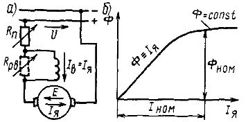
In this electric motor (Fig. 1, a), the armature winding is connected to the main direct current source (direct current network, generator or rectifier) with voltage U, and the excitation winding is connected to an auxiliary source with voltage UB. An adjustment rheostat Rрв is included in the excitation winding circuit, and a starting rheostat Rn is included in the armature winding circuit.
The adjusting rheostat is used to regulate the speed of the motor armature, and the starting rheostat is used to limit the current in the armature winding at start-up. Characteristic feature electric motor is that its excitation current Iv does not depend on the current Ii in the armature winding (load current). Therefore, neglecting the demagnetizing effect of the armature reaction, we can approximately assume that the motor flux Ф does not depend on the load. Dependences of the electromagnetic moment M and the rotation frequency n on the current Iя will be linear (Fig. 2, a). Consequently, the mechanical characteristic of the engine will also be linear - the dependence n (M) (Fig. 2, b).
In the absence of a rheostat with a resistance Rn in the armature circuit, the speed and mechanical characteristics will be rigid, i.e., with a small angle of inclination to the horizontal axis, since the voltage drop IяΣRя in the machine windings included in the armature circuit at a rated load is only 3-5 % of Unom. These characteristics (straight lines 1 in Fig. 2, a and b) are called natural. When a rheostat with resistance Rn is included in the armature circuit, the angle of inclination of these characteristics increases, as a result of which a family of rheostat characteristics 2, 3 and 4 can be obtained, corresponding to different values of Rn1, Rn2 and Rn3.
Rice. 1. Schematic diagrams of electric motors direct current with independent (a) and parallel (b) excitation

Rice. 2. Characteristics of electric motors direct current with independent and parallel excitation: a - high-speed and torque, b - mechanical, c - working The greater the resistance Rn, the greater the angle of inclination of the rheostat characteristic, that is, the softer it is.
The adjusting rheostat Rpv allows you to change the excitation current of the motor Iv and its magnetic flux F. In this case, the rotation frequency n will also change.
No switches and fuses are installed in the excitation winding circuit, since when this circuit is broken, the magnetic flux of the electric motor sharply decreases (only the flux from residual magnetism remains in it) and arises emergency mode... If the electric motor is idling or with a light load on the shaft, the speed rises sharply (the engine is racing). In this case, the current in the armature winding Iя increases greatly and an all-round fire may occur. To avoid this, the protection must disconnect the electric motor from the power source.
A sharp increase in the frequency of rotation when the circuit of the excitation winding is broken is explained by the fact that in this case the magnetic flux F (to the value of the Fost flux from residual magnetism) and e. etc. with. E and the current Iya increases. And since the applied voltage U remains unchanged, the rotation frequency n will increase until e. etc. with. E will not reach a value approximately equal to U (which is necessary for the equilibrium state of the electric armature circuit, at which E = U - IяΣRя.
When the load on the shaft is close to the nominal, the electric motor will stop in the event of a break in the excitation circuit, since the electromagnetic moment that the motor can develop with a significant decrease in the magnetic flux decreases and becomes less than the load torque on the shaft. In this case, the current Iya also increases sharply, and the machine must be disconnected from the power source.
It should be noted that the rotational speed n0 corresponds to an ideal idle speed when the engine does not consume electrical energy from the network and its electromagnetic moment is zero. In real conditions in the mode idle move the motor consumes from the network the no-load current I0, which is necessary to compensate for the internal power losses, and develops a certain torque M0, required to overcome the friction forces in the machine. Therefore, in reality, the idle speed is less than n0.
The dependence of the rotational speed n and the electromagnetic moment M on the power P2 (Fig. 2, c) on the motor shaft, as follows from the considered relations, is linear. The dependences of the armature winding current Iя and power P1 on P2 are also practically linear. The current I and the power P1 at P2 = 0 represent the no-load current I0 and the power P0 consumed at no-load. The efficiency curve has a character common to all electrical machines.
Electric motor direct current parallel excitation
In this electric motor (see Fig. 1, b), the excitation windings and armatures are powered from the same source of electrical energy with voltage U. An adjustment rheostat Rpv is included in the excitation winding circuit, and a starting rheostat Rp is included in the armature winding circuit.
In the electric motor under consideration, there is essentially a separate supply of the armature and excitation winding circuits, as a result of which the excitation current Iv does not depend on the armature winding current Iv. Therefore, the parallel excitation motor will have the same characteristics as the independent excitation motor. However, a parallel excitation motor will only operate normally when powered from a constant voltage constant current source.
When the electric motor is powered from a source with varying voltage (generator or controlled rectifier), a decrease in the supply voltage U causes a corresponding decrease in the excitation current Iв and the magnetic flux Ф, which leads to an increase in the armature winding current Iя. This limits the possibility of adjusting the armature speed by changing the supply voltage U. Therefore, electric motors intended for power supply from a generator or controlled rectifier must have independent excitation.
Electric motor direct current sequentially aroused
To limit the current at start-up, the starting rheostat Rp is included in the armature winding circuit (Fig. 3, a), and to regulate the rotational speed in parallel with the excitation winding, an adjusting rheostat Rpv can be switched on.
Rice. 3. Schematic diagram of the electric motor direct current with sequential excitation (a) and the dependence of its magnetic flux Ф on the current Iя in the armature winding (b)

Rice. 4. Characteristics of the electric motor direct current with sequential excitation: a - high-speed and torque, b - mechanical, c - workers.
A characteristic feature of this electric motor is that its excitation current Iv is equal or proportional (when the rheostat Rpv is turned on) to the armature winding current Ii, therefore the magnetic flux Ф depends on the motor load (Fig. 3, b).
When the current of the armature winding Iya is less (0.8-0.9) of the rated current Inom, the magnetic system of the machine is not saturated and it can be assumed that the magnetic flux Ф changes in direct proportion to the current Iя. That's why speed characteristic the electric motor will be soft - with an increase in the current I, the rotational speed n will sharply decrease (Fig. 4, a). A decrease in the rotational speed n occurs due to an increase in the voltage drop IяΣRя. in the internal resistance Rя. armature winding circuits, as well as due to an increase in the magnetic flux F.
The electromagnetic moment M with an increase in the current Iя will sharply increase, since in this case the magnetic flux Ф also increases, that is, the moment M will be proportional to the current Iя. Therefore, at a current Iya less (0.8 N-0.9) Inom, the speed characteristic has the form of a hyperbola, and the moment characteristic has the form of a parabola.
At currents Iа> Iа, the dependences of M and n on Iа are linear, since in this mode the magnetic circuit will be saturated and the magnetic flux Ф will not change when the current Iа changes.
The mechanical characteristic, that is, the dependence of n on M (Fig. 4, b), can be constructed on the basis of the dependences of n and M on Iya. In addition to the natural characteristic 1, it is possible to obtain a family of rheostat characteristics 2, 3 and 4 by including a rheostat with resistance Rp into the armature winding circuit. These characteristics correspond to different values of Rn1, Rn2 and Rn3, while the more Rn, the lower the characteristic is.
The mechanical characteristic of the engine under consideration is soft and hyperbolic. At low loads, the magnetic flux Ф decreases greatly, the rotational speed n rises sharply and can exceed the maximum allowable value (the engine is running wild). Therefore, such motors cannot be used to drive mechanisms operating in idle mode and at low load (various machines, conveyors, etc.).
Usually minimal permissible load for engines of large and medium power is (0.2 ... 0.25) Inom. To prevent the engine from operating without load, it is rigidly connected to the drive mechanism (gear or blind clutch); the use of a belt drive or friction clutch is unacceptable.
Despite this disadvantage, motors with sequential excitation are widely used, especially where there are wide variations in the load torque and severe starting conditions: in all traction drives (electric locomotives, diesel locomotives, electric trains, electric cars, electric forklifts, etc.), as well as in drives of lifting mechanisms (cranes, elevators, etc.).
This is explained by the fact that, with a soft characteristic, an increase in the load torque leads to a lower increase in current and power consumption than in motors with independent and parallel excitation, therefore, motors with series excitation can withstand overloads better. In addition, these motors have a higher starting torque than motors with parallel and independent excitation, since with an increase in the armature winding current during start-up, the magnetic flux also increases accordingly.
If we accept, for example, that a short-term starting current can be 2 times higher than the rated operating current of the machine, and neglect the effect of saturation, armature reaction and voltage drop in the circuit of its winding, then in a motor with series excitation, the starting torque will be 4 times higher than the nominal (both current and magnetic flux increase by 2 times) ), and in motors with independent and parallel excitation - only 2 times more.
In fact, due to saturation of the magnetic circuit, the magnetic flux does not increase in proportion to the current, but nevertheless, the starting torque of a motor with series excitation, all other things being equal, will be much greater than the starting torque of the same motor with independent or parallel excitation.
The dependences of n and M on the power P2 on the motor shaft (Fig. 4, c), as follows from the positions considered above, are nonlinear, the dependences of P1, Iя and η on P2 have the same form as in motors with parallel excitation.
Electric motor direct current with mixed excitement
In this electric motor (Fig. 5, a), the magnetic flux Ф is created as a result of the joint action of two excitation windings - parallel (or independent) and series, through which the excitation currents Iв1 and Iв2 = Iя
That's why
![]()
where Фпосл - the magnetic flux of the serial winding, depending on the current Iя, Фпар - the magnetic flux of the parallel winding, which does not depend on the load (determined by the excitation current Iв1).
The mechanical characteristic of an electric motor with mixed excitation (Fig. 5, b) is located between the characteristics of motors with parallel (straight line 1) and sequential (curve 2) excitation. Depending on the ratio of the magnetomotive forces of parallel and series windings at the nominal mode, it is possible to approximate the characteristics of a mixed-excitation motor to characteristic 1 (curve 3 with a small ppm of a serial winding) or to characteristic 2 (curve 4 with a small ppm. with. parallel winding).

Rice. 5. Schematic diagram of an electric motor with mixed excitation (a) and its mechanical characteristics (b)
The advantage of the engine direct current with mixed excitation is that it, having a soft mechanical characteristic, can work at idle, when Fposl = 0. In this mode, the frequency of rotation of its armature is determined by the magnetic flux Fpar and has a limited value (the engine is not peddling).
[document]1.doc
Homework # 2(module 5)
“DC motor with series excitation. Appointment of elements. Principle of operation"
group TP-07
Asmolkova O. A.
I semester 2009
DC motor with series excitation. Appointment of elements. Principle of operation
1.Design and purpose of elements of a DC motor
.
DC motor - electric car , dc machine transforming electrical energy direct current into mechanical energy. It consists, like all DC machines, of a stationary stator with poles and a rotating rotor (armature) with a collector.
Stator DC machine consists of a cylindrical frame (housing), poles with excitation winding and end shields ( rice. 2.1.). On the frame, the main (main) poles are strengthened to excite the main magnetic flux and additional poles to improve the commutation in the motor. The main pole consists of a pole core, assembled from sheet steel and bolted to the frame, and an excitation coil. The core at the free end is equipped with a pole piece to create the required distribution of magnetic induction along the circumference of the armature. Stanina 3 is the yoke of the machine, that is, the part that closes the magnetic circuit of the main flux F. It is made of cast steel, since the magnetic flux in it is relatively constant. Additional poles are installed on the bed between the main ones. Their winding is connected in series with the armature winding. The purpose of these poles is to create an additional magnetic field. This is to prevent sparking from the brushes on the collector.
Anchor (rotor) is a part of a machine, in the winding of which, when it rotates relative to the main magnetic field, an EMF is induced. Anchor 5 DC motor consists of a steel shaft, a steel gear core, a winding laid in its slots, and a collector mounted on the armature shaft ( rice. 2.1.). The field windings are necessary to ensure optimal interaction between the magnetic fields of the rotor and stator (i.e., maximize rotor torque). A characteristic part of the engine (or any electric machine) DC is the collector. It is a hollow cylinder assembled from insulated wedge-shaped copper plates. The manifold plates are also insulated from the motor shaft. They are connected by conductors to the winding threads placed in the armature grooves. The rotating winding is connected to the external circuit by a sliding contact between the brushes and the collector. The collector in DC machines serves to straighten the variable EMF induced in the rotating armature winding and to obtain a constant electromagnetic moment in the direction.
Rice. 2. 1. DC motor device:
1 - excitation winding;2 - poles;3 - bed;4 - pole piece;5 - anchor;6 - conductors of the anchor winding;
7 - toothed armature core;8 - machine air gap
2. The principle of operation of the DC motor
2.1 General
When the armature winding rotates in a stationary magnetic field, a variable EMF is induced in it, which changes with frequency:
Where n- the speed of rotation of the armature.
When the armature rotates between any two points of the armature winding, a variable EMF acts. However, an EMF constant in magnitude and direction acts between the fixed contact brushes E, equal to the sum of the instantaneous values of the EMF induced in all series-connected turns of the armature located between these brushes.
EMF dependence E from the magnetic flux of the machine and the speed of rotation of the armature has the form:
When connecting the armature winding to the mains with voltage U, EMF E will be approximately equal to voltage U, and the rotor speed:
Consequently, due to the presence of a collector when a DC machine is operating in a motor mode, the rotor speed is not rigidly connected with the mains frequency, but can vary over a wide range by changing the voltage U and magnetic flux F... The axis of symmetry that separates the poles of a DC machine is called its geometric neutral.
With an open external circuit, the current in the armature winding will not flow, since the EMF induced in two parts of the armature winding, located on both sides of the geometric neutral, are directed oppositely and mutually compensate. In order to apply the maximum voltage from the armature winding to the external circuit, this circuit must be connected to two points of the armature winding, between which the greatest potential difference acts, where the brushes should be installed. When the armature rotates, the points are displaced from the geometric neutral, but more and more points of the winding will approach the brushes, between which the EMF acts E, therefore, the EMF in the external circuit will be unchanged in magnitude and direction. To reduce the EMF ripple when the brushes move from one collector plate to another, at least 16 active conductors are usually included in each parallel armature winding branch.
On the armature, through the winding of which current flows I, the electromagnetic moment acts:
When the machine is operating in motor mode, the electromagnetic torque is rotating.
2.2 Armature response of a DC motor
At idle, the magnetic flux in the engine is created only by the HC ^ F in the excitation winding. In this case, the magnetic flux F v with a constant air gap between the armature and the core of the main pole (which is typical for many DC machines), it is distributed symmetrically relative to the longitudinal axis of the machines.
When the machine is operating under load, a current flows through the armature winding, and the armature NS creates its own magnetic field. The effect of the armature field on the magnetic field of the machine is called anchor reaction... Magnetic flux F aq created by NS anchors F aq in a two-pole machine, when the brushes are installed in neutral, it is directed along transverse axis machines, therefore the magnetic field of the armature is called transverse. As a result of the action of the stream F aq the symmetrical distribution of the machine's magnetic field is distorted and the resulting flux F cut turns out to be concentrated mainly at the edges of the main poles. In this case, the physical neutral bb(the line connecting the points of the armature circle at which the induction is zero) is displaced relative to the geometric neutral a-a by some angle β (fig.2.2). In motors, the physical neutral is shifted against the direction of rotation.
Based on the law of the total current of the armature NS, acting in the air gap at a distance x from the axis of the main poles, is determined by the expression:
Therefore, the NS anchors F aq changes linearly along its circumference; under the middle of the main pole, it is zero, and at the points where the brushes are installed, it has a maximum value. Magnetic induction in air
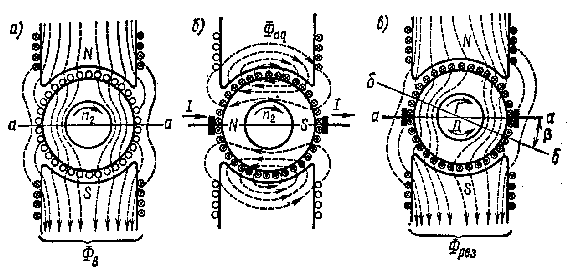
^ Figure 2.2 - Magnetic field of a DC motor: a) from the excitation winding; b) from the armature winding; c) the resulting (Ф v - magnetic flux at c.h .; F aq - the magnetic flux created by the NS of the armature; F cut - the resulting stream; a-a - geometric neutral; bb - physical neutral; β - neutral displacement angle b-b)
Unsaturated magnetic system gap:
Where is the size of the air gap at point x.
2.3 Torque of DC motor
If the field winding and the motor armature are connected to the DC mains with voltage ^ U then, there is an electromagnetic torque M Em... Useful torque M on the motor shaft is less than the electromagnetic one by the value of the counteracting moment created in the machine by frictional forces and equal to the moment M NS in the x.x. mode, i.e. M = M Em -M NS .
The starting torque of the motor must be greater than the static braking torque. M t at rest of the rotor, otherwise the engine armature will not start rotating. In the steady state (for n = const), there is an equilibrium of the rotating M and braking M t moments:
M = M Em - M NS = M T
It is known from mechanics that the mechanical power of the engine can be expressed in terms of the torque and angular velocity
Therefore, the useful torque of the motor ^ M(Nm) expressed in terms of net power R(kW) and speed n(rpm),
M = 9550P / n
Let's discuss some important issues of starting and operating DC motors. From the equation of the electric state of the engine it follows that
I I am = (U - E) / R I am
In the operating mode, the armature current I I is limited by e. etc. with. E if n is approximately equal to n nom... At the time of launch, n = 0, e. etc. with. E = 0 and starting current I NS = U/ R I am 10-30 times more than the nominal. Therefore, direct starting of the engine, i.e. direct connection of the armature to the mains voltage, is unacceptable. To limit the large starting current of the armature, a starting rheostat is turned on in series with the armature before starting. R NS with little resistance. In this case, for E = O
I NS = U / (R I am - R NS ) << U/R I am
Rheostat resistance RNS is selected according to the permissible armature current.
As the engine accelerates to the rated speed of the e. etc. with. E increases, and the current decreases and the starting rheostat is gradually and completely removed (starting rheostats are designed for short-term switching on). Adjusting rheostat R reg in the excitation circuit with a relatively high resistance (tens and hundreds of Ohms), before starting the engine, it is completely removed so that the excitation current and the stator magnetic flux during start-up F were nominal. This results in an increased starting torque, which allows the engine to accelerate quickly and easily.
After starting and acceleration, a steady state of operation of the motor occurs, in which the braking torque on the shaft ^ Mt will be balanced by the torque developed by the engine M Em , i.e. M Em == M T ( at n = withnst. )
DC motors can restore the steady-state operating mode disturbed by a change in the braking torque, i.e. they can develop a torque M, equal to the new value of the braking torque M T at a correspondingly new speed n".
Indeed, if the braking torque of the load Mt turns out to be greater than the torque of the engine M Em, then the frequency of rotation of the armature will decrease. With constant voltage U and flow F this will cause a decrease in e. etc. with. E armature, an increase in armature current and torque until equilibrium is reached, at which M Em = M T and n" < n. With a decrease in the braking torque to Mt, a steady state of operation occurs similarly at M Em = M T" and n"> n" . Thus, DC motors are self-regulating. - can develop a torque equal to the braking torque.
2.4 Frequency regulation
The armature speed of a DC motor is determined based on the equation of electrical state U= ER I am I I am after substituting e. etc. with. E = sFn:

Anchor voltage drop R I am I I am small: at rated load it does not exceed 0,03 - 0,07 U nom .
Thus, the speed of the DC motor is directly proportional to the applied mains voltage and inversely proportional to the stator magnetic flux. . There are two ways to regulate the engine speed: by changing the stator flux Ф or the voltage U supplied to the motor. The regulation of the rotational speed by changing the magnetic field of the machine is carried out using an adjusting rheostat in the motor excitation circuit. The voltage supplied to the motor is changed by adjusting the voltage of the source.
An additional rheostat can be introduced into the armature circuit. In this case, the starting rheostat is replaced by a ballast R NS Such a rheostat performs the functions of both a starting rheostat and an adjusting one. In this case, the equation for the rotation frequency of the armature of a DC motor has the form

From this it follows that the regulation of the engine speed can be carried out by changing the mains voltage, the resistance of the ballast rheostat or the stator flux.
Reversing motors. From the motor torque equation M Em = kFI I am it follows that reversing, i.e. changing the direction of rotation of the armature, can be carried out by changing the direction of the current in the excitation winding (flow F) or armature current.
To reverse the motor "on the fly", the direction of the armature current is changed (by switching the armature leads), and the excitation winding is not switched, since it has a high inductance and breaking its circuit with current is unacceptable. The reversal of the switched off motor is also carried out by changing the direction of the current in the field winding (by switching its terminals).
3. Motor with series excitation
In a motor with series excitation ( fig. 2.3a) the excitation current is equal to the armature current: I v = I a, therefore, the magnetic flux Ф is a function of the load current I a... The nature of this function changes depending on the magnitude of the load. At I a <(0,8...0,9) I nom when the magnetic system is unsaturated, F = k f I a, and the proportionality coefficient TO f remains practically constant over a wide range of loads. With a further increase in the load, the flow F grows slower than I a > I nom) we can assume that Ф = const... In accordance with this, the dependencies also change. n = f (I a ), M = f (I a) (rice. 2.3.b).

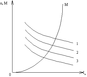
Rice. 2.3. - a) circuit of the motor with series excitation; b) the dependence of its torque and speed of rotation on the armature current (I I am - armature current; I v - excitation current;r n
- load resistance;
n- rotational speed; 1 - natural characteristic; 2,3 - rheostatic characteristics corresponding to different values of additional resistance r n ).
In addition to the natural characteristics 1, it is possible, by including additional resistances r n in the armature circuit, to obtain a family of rheostat characteristics 2, 3, and 4. The larger the value of r n, the lower the characteristic is.
At low loads, the speed n rises sharply and can exceed the maximum allowable value (the engine goes into "runaway"). Therefore, such motors cannot be used to drive mechanisms operating in idle mode and at low load.
With a rigid characteristic, the rotation speed n is almost independent of the moment M, therefore the power is:
![]() , where WITH 4
- constant.
, where WITH 4
- constant.
With a soft motor characteristic, n is inversely proportional, as a result of which:
![]() , where is a constant.
, where is a constant.
Therefore, when the load torque changes over a wide range, the power R 2 , and, therefore, the power R 1 and current I a change in series excitation motors to a lesser extent than in parallel excitation motors, in addition, they tolerate overloads better.
In this engine, the field winding is connected in series to the armature circuit (Fig. 29.9, a), therefore magnetic fluxF it depends on the load current I = I a = I in ... At low loads, the magnetic system of the machine is not saturated and the dependence of the magnetic flux on the load current is directly proportional, i.e. Ф = k Ф I a (k f- coefficient of proportionality). In this case, we find the electromagnetic moment:
The formula for the rotational speed will take the form
 . (29.15)
In fig. 29.9, b performance characteristics are presented M = F (I) and n = (I) sequential excitation motor. At high loads, saturation of the magnetic system of the motor occurs. In this case, the magnetic flux practically does not change with increasing load and the characteristics of the motor acquire an almost straight-line character. The speed characteristic of a series-excited motor shows that the speed of the motor changes significantly with changes in load. This characteristic is usually called soft.

Rice. 29.9. Sequential excitation motor:
a- circuit diagram; b- performance characteristics; c - mechanical characteristics; 1 - natural characteristic; 2 - artificial characteristic
With a decrease in the load of the sequential excitation motor, the rotational speed increases sharply and at a load of less than 25% of the nominal one can reach values dangerous for the motor ("spacing"). Therefore, the operation of a sequential excitation motor or its start with a load on the shaft less than 25% of the nominal is unacceptable.
For more reliable operation, the shaft of a sequential excitation motor must be rigidly connected to the working mechanism by means of a coupling and a gear train. The use of a belt drive is unacceptable, as if the belt breaks or drops, the engine may "run out". Taking into account the possibility of engine operation at increased speeds, sequential excitation motors, according to GOST, are tested for 2 minutes to exceed the speed by 20% above the maximum specified on the factory panel, but not less than 50% above the rated speed.
Mechanical characteristics of a series excitation motor n = f (M) are shown in Fig. 29.9, v. Sharply falling curves of mechanical characteristics ( natural 1 and artificial 2 ) provide the sequential excitation motor with stable operation under any mechanical load. The ability of these motors to develop a large torque proportional to the square of the load current is important, especially under severe starting conditions and with overloads, since with a gradual increase in the load of the motor, its input power rises more slowly than the torque. This feature of sequential excitation motors is one of the reasons for their widespread use as traction motors in transport, as well as crane motors in hoisting installations, i.e. in all cases of an electric drive with severe starting conditions and a combination of significant loads on the motor shaft with low rotation frequency.
Rated change in the speed of the motor of series excitation
 , (29.16)
where n - rotational speed at engine load, which is 25% of the nominal.
The rotational speed of series excitation motors can be adjusted by changing either voltage U, or the magnetic flux of the field winding. In the first case, an adjusting rheostat R pr (fig. 29.10, a). With an increase in the resistance of this rheostat, the voltage at the input of the motor and the frequency of its rotation decrease. This control method is used mainly in low-power engines. In the case of a significant engine power, this method is uneconomical due to large energy losses in R pg ... Besides, rheostat R pr , calculated for the operating current of the motor is cumbersome and expensive.
When several engines of the same type work together, the rotational speed is regulated by changing the circuit of their connection relative to each other (Fig. 29.10, b). So, when the motors are connected in parallel, each of them is under full mains voltage, and when two motors are connected in series, each motor has half the mains voltage. With the simultaneous operation of more motors, more switching options are possible. This method of speed control is used in electric locomotives, where several identical traction motors are installed.
Changing the voltage supplied to the motor is possible when the motor is powered from a DC source with adjustable voltage (for example, according to a circuit similar to Fig. 29.6, a). With a decrease in the voltage supplied to the engine, its mechanical characteristics shift downward, practically without changing their curvature (Fig. 29.11).

Rice. 29.11. Mechanical characteristics of a series excitation motor with a change in the applied voltage
There are three ways to adjust the engine speed by changing the magnetic flux: by shunting the excitation winding with a rheostat r pg , sectioning the excitation winding and shunting the armature winding with a rheostat r w . Turning on the rheostat r pg , shunting the excitation winding (Fig. 29.10, v), and also a decrease in the resistance of this rheostat leads to a decrease in the excitation current I in = I a - I pg , and, consequently, to an increase in the rotational speed. This method is more economical than the previous one (see fig. 29.10, a), is used more often and is estimated by the regulation coefficient
 .
.
Usually the resistance of the rheostat r pg taken so that k рг> = 50% .
When sectioning the excitation winding (Fig. 29.10, G) turning off part of the winding turns is accompanied by an increase in the rotation frequency. When shunting the armature winding with a rheostat r w (see fig. 29.10, v) the excitation current increases I in = I a + I pg , which causes a decrease in the rotational speed. This method of regulation, although it provides deep regulation, is uneconomical and is used very rarely.

Rice. 29.10. Speed control of series excitation motors