Electric current is the main type of energy that does useful work in all spheres of human life. It sets in motion various mechanisms, gives light, heats houses and revives a whole variety of devices that ensure our comfortable existence on the planet. Truly, this type of energy is universal. Anything can be obtained from it, and even great destruction with inept use.
But there was a time when electrical effects were still present in nature, but did not help humans in any way. What has changed since then? People began to study physical phenomena and came up with interesting cars- converters, which, in general, made a revolutionary leap in our civilization, allowing a person to receive one energy from another.
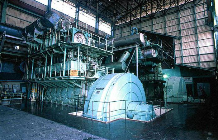
So people learned to generate electricity from ordinary metal, magnets and mechanical movement- that's all. Generators were built that were capable of delivering enormous power streams of energy, calculated in megawatts. But it is interesting that the principle of operation of these machines is not so complicated and may well be understandable even for a teenager. What is it Let's try to understand this issue.
Electromagnetic induction effect
The basis for the appearance in the conductor of electric current is electromotive force- EMF. It is able to make charged particles move, which are many in any metal. This force appears only if the conductor experiences a change in the intensity of the magnetic field. The effect itself is called electromagnetic induction. EMF themes more, the greater the rate of change of the flux of magnetic waves. That is, you can move a conductor near a permanent magnet, or influence a stationary wire with the field of an electromagnet, changing its strength, the effect will be the same - an electric current will appear in the conductor.
Scientists Oersted and Faraday worked on this issue in the first half of the 19th century. They also discovered this physical phenomenon. Subsequently, current generators and electric motors were created on the basis of electromagnetic induction. Interestingly, these machines can be easily converted to each other.
How DC and AC generators work
It is clear that an electric current generator is an electromechanical machine that generates current. But in fact, it is a converter of energy: wind, water, heat, anything in the EMF, which already causes a current in the conductor. The device of any generator is fundamentally no different from a closed conducting loop that rotates between the poles of a magnet, as in the first experiments of scientists. Only much greater is the magnitude of the magnetic flux created by powerful permanent or more often electric magnets. The closed loop has the form of a multi-turn winding, which in modern generator not one, but at least three. All this is done in order to obtain the largest possible EMF.
A standard electrical alternator (or direct current) consists of:
- Housings... It serves as a frame, inside which a stator with electromagnet poles is attached. It contains a rotor shaft. It is made of metal and protects the entire interior of the machine.
- Stator with magnetic poles. A magnetic flux excitation winding is fixed on it. It is made of ferromagnetic steel.
- Rotor or armature. This is the movable part of the generator, the shaft of which is driven by an external force in rotational motion. A self-excitation winding is located on the armature core, where an electric current is generated.
- Switching node. This structural element serves to divert electricity from the movable shaft of the rotor. It includes conductive rings that are movably connected to graphite collector contacts.
DC Generation
In a generator producing direct current, the conducting loop rotates in the magnetic saturation space. Moreover, for a certain moment of rotation, each half of the circuit is near one or another pole. During this half-turn, the charge in the conductor moves in one direction.
To obtain the removal of particles, an energy removal mechanism has been made. Its peculiarity is that each half of the winding (frame) is connected to a conductive half-ring. The half rings are not closed to each other, but are fixed on a dielectric material. During the period when one part of the winding begins to pass a certain pole, the semi-ring closes in electrical circuit brush contact groups... It turns out that only one type of potential comes to each terminal.
It is more correct to call energy not constant, but pulsating, with constant polarity. Ripple is caused by the fact that the magnetic flux on the conductor during rotation has both maximum and minimum impact. To even out this ripple, several windings are used on the rotor and powerful capacitors at the input of the circuit. To reduce the loss of magnetic flux, the gap between the armature and the stator is minimized.
Alternator circuit
When the moving part of the current-generating device rotates, EMF is also induced in the frame conductors, as in the DC generator. But a small feature - the alternator device of the collector unit has another. In it, each terminal is connected to its own conductive ring.
The principle of operation of the alternator is as follows: when half of the winding passes near one pole (the other, respectively, near the opposite pole), the current moves in the circuit in one direction from its minimum to its highest value and again to zero. As soon as the windings change their position relative to the poles, the current begins to move in the opposite direction with the same pattern.
In this case, at the input of the circuit, a signal waveform is obtained in the form of a sinusoid with a half-wave frequency corresponding to the period of rotation of the rotor shaft. In order to obtain a stable signal at the output, where the frequency of the alternator is constant, the rotation period of the mechanical part must be constant.

gas type
The designs of current generators, where instead of a metal frame, conductive plasma, liquid or gas are used as a charge carrier, are called MHD generators. Substances under pressure are driven into a magnetic field. Under the influence of the same EMF of induction, charged particles acquire directional movement, creating an electric current. The magnitude of the current is directly proportional to the speed of passage through the magnetic flux, as well as its power.
MHD generators have a simpler design solution - they do not have a rotor rotation mechanism. Such power supplies are capable of delivering large amounts of power in short periods of time. They are used as backup devices and in emergency situations. The coefficient that determines the efficiency (efficiency) of these machines is higher than that of an electric alternator.
Synchronous alternator
There are these types of alternators:
- Synchronous machines.
- Asynchronous machines.
A synchronous alternator has a strict physical relationship between the rotational motion of the rotor and the generated frequency of electricity. In such systems, the rotor is an electromagnet, assembled from cores, poles and field windings. The latter are powered from a direct current source by means of brushes and ring contacts. The stator, on the other hand, is a coil of wire, interconnected according to the principle of a star with a common point - zero. An EMF is already induced in them and a current is generated.
The rotor shaft is driven by an external force, usually by turbines, the frequency of which is synchronized and constant. The electrical circuit connected to such a generator is a three-phase circuit, the frequency of the current in a separate line of which is shifted by a phase of 120 degrees relative to other lines. To obtain a correct sinusoid, the direction of the magnetic flux in the gap between the stator and rotor parts is controlled by the design of the latter.
The alternator is excited by two methods:
- Contact.
- Contactless.
In the contact excitation circuit, electricity from another generator is supplied to the electromagnet windings through a brush pair. This generator can be combined with the main shaft. It is usually less powerful, but sufficient to create a strong magnetic field.
The contactless principle provides that a synchronous alternator on the shaft has additional three-phase windings, in which EMF is induced during rotation and electricity is generated. It is fed through a rectifying circuit to the rotor excitation coils. Structurally, such a system has no moving contacts, which simplifies the system, making it more reliable.
Asynchronous generator
There is an asynchronous alternator. Its device differs from the synchronous one. There is no exact dependence of the EMF on the frequency with which the rotor shaft rotates. There is such a thing as "S slip" that characterizes this difference in influence. The amount of slip is determined by calculation, so it is wrong to think that there is no regularity in the electromechanical process in an induction motor.
If the idle generator is loaded, then the current flowing in the windings will create a magnetic flux that prevents the rotor from rotating at a given frequency. This is how slip is formed, which naturally affects the generation of EMF.
The modern asynchronous alternator has three different designs for the moving part:
- Hollow rotor.
- Squirrel cage rotor.
- Phase rotor.
Such machines can have self- and independent excitation. The first scheme is implemented by including capacitors and semiconductor converters in the winding. An independent type of excitation is created by an additional AC source.
Generator wiring diagrams
All powerful power supplies produce three-phase electrical current. They contain three windings in which alternating currents are formed with phase shifted from each other by 1/3 of the period. If we consider each individual winding of such a power source, then we get a single-phase alternating current going into the line. A generator can generate tens of thousands of volts. the consumer receives from the distribution transformer.
Any alternator has a standard winding device, but there are two types of connection to the load:
- star;
- triangle.
The principle of operation of a star-connected alternator involves combining all wires (neutral) into one, which go from the load back to the generator. This is due to the fact that the signal (electric current) is transmitted mainly through the outgoing winding wire (linear), which is called the phase. In practice, this is very convenient, because you do not need to pull three additional wires to connect the consumer. The voltage between the line wires and the line and neutral wire will differ.
Connecting the generator windings with a triangle, they are closed with each other in series in one circuit. From the points of their connection, lines are drawn to the consumer. Then it is not needed at all and the voltage on each line will be the same regardless of the load.
The advantage of a three-phase current over a single-phase current is its lower ripple during rectification. This has a positive effect on powered devices, especially DC motors. Also, a three-phase current creates a rotating magnetic field flux, which is capable of driving powerful induction motors.
Where DC and AC generators are applicable
DC generators are significantly smaller and lighter than machines alternating voltage... Having a more complex design than the latter, they have nevertheless found application in many industries.
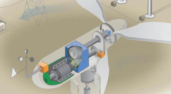
They are mainly used as high-speed drives in machines where speed control is required, for example, in metalworking mechanisms, mine hoists, and rolling mills. In transport, such generators are installed on diesel locomotives and various ships. Many models of wind generators are assembled on the basis of constant voltage sources.
Special-purpose DC generators are used in welding, to excite the windings of synchronous-type generators, as DC amplifiers, to power galvanic and electrolysis installations.
The purpose of the alternator is to generate electricity on an industrial scale. This kind of energy was presented to humanity by Nikola Tesla. Why is it a polarity-reversing current, and not a constant one, that has found widespread use? This is due to the fact that when transmitting constant voltage, there are large losses in the wires. And the longer the wire, the higher the losses. Alternating voltages can be transported over great distances at a much lower cost. Moreover, you can easily convert an alternating voltage (lowering and increasing it), which was produced by a 220 V generator.
Conclusion
Man has not fully cognized the nature of magnetism that permeates everything around him. AND Electric Energy- this is only a small part of the open secrets of the universe. The machines that we call power generators are inherently very simple, but what they can give us is simply amazing. Yet the real miracle here is not in technology, but in human thought, which was able to penetrate into the inexhaustible reservoir of ideas poured into space!
In order to ensure the most comfortable existence, man has developed and invented a huge variety of different technological devices and complex systems. But one of the most efficient and effective devices for using electricity has become an alternator. Get acquainted with the types and types of RCDs.
Today, there are two main types of construction:
- Devices with a fixed part - a stator and a rotating element - a magnetic pole. The elements of this type are widely used among the population, because the presence of a fixed winding saved the user from the need to remove unnecessary electrical load.
- An electrical device with a rotary armature and a fixed magnetic pole.
It turns out that the design of the generator is reduced to the presence of two main parts: movable and fixed, as well as to the elements that serve as a connecting link between them (brushes and wires).
Principle of operation
The working principle of the car alternator:
- the rotating part of the rotor or drive mechanism is nominally taken as an electric magnet. It is he who will transmit the created magnetic field to the stator "body". This is an external element of the device, which consists of coils with wires connected to them.
- voltage is transmitted through rings and manifold shields. The rings are made of copper and rotate simultaneously with the rotor and crankshaft. In the course of movement, the brushes are pressed against the surface of the rings. Consequently, the current will be transferred from the stationary part to the moving part of the system.
Specifications
When buying an alternator, you need to focus on the following specifications:
- Electric power;
- Working voltage;
- The number of revolutions of the rotating part of the generator;
- Useful power factor;
- Current strength.
These values are basic technical characteristics alternating current.
Views
Today on the territory of the Russian Federation they are selling different types certified and unlicensed alternators. Review of household halogen lamps and how to choose here:. The most popular of these devices are the following:
Before proceeding with the principle of operation of an electric generator, you need to understand at least a little with its device.
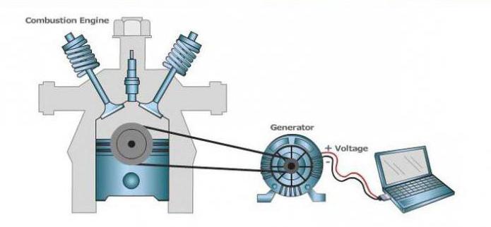
A household electric generator consists of a motor ( power unit) and a generator - a unit that converts mechanical energy into electrical energy. In household mini-power plants, motors are most often used internal combustion- diesel or gasoline. It is not necessary to separate out gas generators, because they are a modified gasoline generator.
Electric generators are synchronous and asynchronous. Which are worse and which are better? From all the literature that I was able to read on the Internet about this, I came to the following conclusion:
Asynchronous power generators. They are cheaper. These generators ensure that the voltage in the network is maintained with high accuracy, therefore, they allow you to connect to them equipment that is sensitive to voltage surges (for example, medical equipment, other electronic devices). Such generators allow you to connect to them power tools and electric motors with reactive power up to 30% of the nominal. These are perhaps their main and only big advantages. Minus - this generator, during start-up, consumes 1.5-3 times the power for a short time. Asynchronous electric generator hardly tolerates peak overloads.
Synchronous generators provide consumers with higher quality electricity than asynchronous ones. They are also capable of withstanding 3-fold starting overloads. In professional and stationary power plants, only synchronous generators are installed. Synchronous generators are less accurate, but, nevertheless, they are suitable for emergency power supply of offices, refrigeration plants, equipment of country houses, summer cottages, construction sites. Such generators can easily cope with the power supply of power tools and electric motors with reactive load up to 65% of their nominal value.
And what is an electric generator?
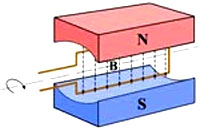 The principle of operation of any electric generator is based on the phenomenon of electromagnetic induction. Electromagnetic induction converts the mechanical energy of the motor (rotation) into electrical energy. The principle of magnetic induction: if a frame rotates uniformly in a uniform magnetic field B, then a variable EDS arises in it, the frequency of which is equal to the frequency of rotation of the frame. Whether we rotate the frame in a magnetic field, or a magnetic field around the frame, or a magnetic field inside the frame, the result will be the same - EDS, changing according to a harmonic law.
Now let's talk about the asynchronous and synchronous generator in more detail.
Synchronous generator
is a synchronous machine operating in the generator mode in which the frequency of rotation of the stator magnetic field is equal to the frequency of rotation of the rotor. A rotor with magnetic poles creates a rotating magnetic field, which, crossing the stator winding, induces an EMF in it. In a synchronous generator, the rotor is made in the form of a permanent magnet or an electromagnet. 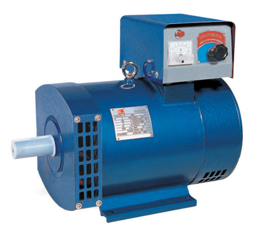 The number of rotor poles can be two, four, etc., but is a multiple of two. In household power plants, as a rule, a rotor with two poles is used, which determines the engine speed of the power plant of 3000 rpm. The rotor, when starting the power plant, creates a weak magnetic field, but with an increase in speed, the EMF in the excitation winding also increases. The voltage from this winding is fed to the rotor through the automatic regulation unit (AVR), controlling the output voltage by changing the magnetic field. For example, a connected inductive load demagnetizes the generator and reduces the voltage, and when a capacitive load is connected, the generator is magnetized and the voltage rises. This is called an "anchor reaction". To ensure the stability of the output voltage, it is necessary to change the magnetic field of the rotor by regulating the current in its winding, which is provided by the AVR unit. The advantage of such generators is the high stability of the output voltage, and the disadvantage is the possibility of overcurrent, since at an overestimated load, the regulator can excessively increase the current in the rotor winding. Another disadvantage of a synchronous generator is the presence of a brush assembly, which sooner or later will have to be serviced. Thanks to this method of regulation, regardless of changes in the load current and engine speed of the power plant, the stability of the generator output voltage remains very high, approximately ± 1%.
An asynchronous machine (motor) operating in braking mode, the rotor of which rotates ahead of time, but in the same direction as the stator magnetic field. Depending on the type of winding, the rotor can be short-circuited or phase. 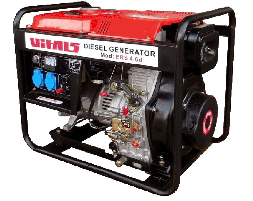 The rotating magnetic field created by the auxiliary stator winding induces a magnetic field on the rotor, which, rotating with the rotor, induces an EMF in the working stator winding, as well as in a synchronous generator. The rotating magnetic field always remains unchanged and unregulated, as a result of which the voltage and frequency at the generator output depends on the rotor speed, and therefore on the stability of the power plant. Despite the ease of maintenance, low sensitivity to short circuit and low cost, asynchronous generators are rarely used, since there are a number of disadvantages: an asynchronous generator always consumes a magnetizing current of significant strength, therefore, for its operation, a reactive power source (capacitors) is required, which depends on actively - inductive nature of the load; unreliability of work in extreme conditions; excitation of an asynchronous generator depends on random factors and occurs, as a rule, at a speed exceeding or equal to the synchronous one; dependence of the output voltage and frequency of the current on the stability of the motor, etc.
It is a type of electrical machine that converts mechanical energy into electrical energy. The operation of current generators is based on the principle of electromagnetic induction: an electromotive force (EMF) is induced in a wire moving in a magnetic field.
Produce current generator can not only direct, but also alternating current. In Latin, the word “generator” means “manufacturer”.
In the world market, the most famous generator suppliers are the following companies: General Electric (GE), ABB, Siemens AG, Mecc Alte.
DC generators.
The only type of source for generating electricity for a long time has been electric generators.
An alternating current is induced in the armature winding of a direct current generator, then it is converted into direct current by an electromechanical rectifier - a collector. Especially at a high rotation frequency of the generator armature, the process of rectifying the current by the collector is associated with very frequent wear of the brushes and the collector.

Differ DC generators by the nature of their excitement, they are self-excited and independent. An excitation winding located at the main poles is connected to an independent power source in generators with electromagnetic excitation.
Permanent magnets, from which the poles of the machine are made, excite generators with magnetoelectric excitation. The main application of DC generators is found in those industries where direct current is preferable in terms of production conditions (enterprises of the electrolysis and metallurgical industries, ships, transport and others). DC generators are used as sources of direct current and exciters of synchronous generators in power plants.
Can reach up to 10 Megawatts generator power.
With a sufficiently high voltage, large currents can be obtained alternators... Several types of induction generators are currently distinguished.
They consist of a permanent magnet or electromagnet creating a magnetic field and a winding in which an alternating EMF is induced. Since the EMF induced in series-connected turns are added, the EMF amplitude in the induction frame will be proportional to the number of turns in it. It is also proportional through each turn to the amplitude of the alternating magnetic flux. V generators To obtain a large magnetic flux, a special magnetic system is used, consisting of two cores made of electrical steel. In the grooves of one of the cores there are windings that create a magnetic field, and in the grooves of the second there are windings in which an EMF is induced. One of the cores is called a rotor because it rotates around a vertical or horizontal axis, along with its winding.

Another core is called a stator - it is a fixed core with its winding. The gap between the rotor and stator cores is made as small as possible, the greatest value of the flux of magnetic induction is provided by this. An electromagnet, which is a rotor, rotates in large industrial generators, and the windings laid in the grooves of the stator and in which the EMF is induced remain stationary.
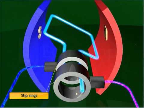
With the help of sliding contacts, it is necessary to supply current to the rotor or withdraw it from the rotor winding into the external circuit. For this, the rotor is supplied with slip rings, which are attached to the ends of its winding. Fixed brush plates are pressed to the rings, they communicate with the external circuit of the rotor winding. In the windings of an electromagnet creating a magnetic field, the current strength is much less than the current strength that the current generator gives to the external circuit. Therefore, it is much more convenient to remove the generated current from the stationary windings, and to supply a relatively weak current through sliding contacts to the rotating electromagnet. This current is generated, located on the same shaft by a separate DC generator(pathogen). A rotating magnet creates a magnetic field in low-power current generators, brushes and rings in this case are not required at all.

There are two types of excitation windings of synchronous generators: with salient-pole and implicit-pole rotors. Carrying excitation windings in generators with salient pole rotors protrude from the inductor. Generators of this type are designed for relatively low rotational speeds; they are used to operate with a piston drive. steam engines, hydro turbines, diesel engines... For drive synchronous generators with implicit-pole rotors, gas and steam turbines are used. A steel forging with milled longitudinal slots for the turns of the field winding, which are usually made in the form of copper plates, is a rotor of such a generator. The turns are fixed in the grooves, and to reduce power losses and noise levels associated with air resistance, the surface of the rotor is ground and then polished.
For the most part, three-phase are made generator windings... Such a combination of moving parts, capable of generating energy also economically and continuously, is rarely found in mechanics.
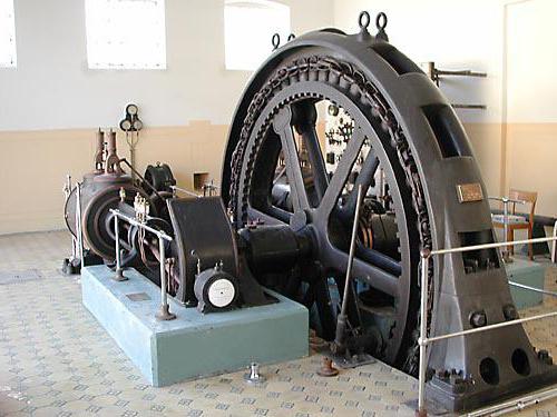
Modern current generator is an imposing structure made up of copper wires, steel structures and insulating materials. With an accuracy of 1 millimeter, the most important parts of the generators are manufactured, which themselves measure several meters.
The generator is designed to supply all electrical systems of the vehicle when the engine is running. Although the battery stores a certain amount of energy, it will quickly deplete due to the limited capacity without recharging. All electricity needs, including recharging the battery, are provided by the generator, which is driven by the engine using a belt drive. DC current is required to recharge the battery, so either a DC generator (dynamo) or an AC generator with rectifier is needed.
Currently, only alternators are used in automotive vehicles due to their advantages. However, before the introduction of semiconductors, DC generators were used.
Because of design features, such DC electric machines had significant drawbacks, for example, the impossibility of charging the battery when the engine was idling.
Due to the widespread adoption electrical devices in the design of the car, the increased demand for electricity, the DC generator was not able to satisfy due to the fact that the power had to be removed from the rotating collector with carbon brushes, since the current is induced in the rotor, while the field windings are stationary (Fig. 1 a).
Rice. 1. Schematic diagrams of generators:
a) direct current (stationary magnetic field),
b) alternating current (rotating magnetic field);
1-anchor; 2-collector with brushes; 3-stator;
F- magnetic flux; I-current; ω - angular velocity
In an alternating current generator (Fig. 1 b), the windings in which the main current is generated are stationary, and the excitation windings are light enough and can rotate at a much higher speed than the rotor of the direct current generator. With an appropriate selection of the drive ratio, the rotor of the alternator can rotate at a sufficient speed to idle give positive power to charge the battery.
The transformation of mechanical energy received by the generator from the engine into electrical energy occurs in accordance with the phenomenon of electromagnetic induction. If the changing magnetic flux penetrates the coil with the turns of the conductive wire isolated from each other, then an EMF appears at the terminals of the coil, proportional to the product of the number of turns by the rate of change of the magnetic flux:
E to = -WLBV,
where W- the number of turns of the frame; B- magnetic induction, T; L- length of part of the frame (conductor), m; V- the vector of the linear velocity of the frame movement relative to the stationary magnetic field, m / s.
The minus sign means that if under the action of EMF ETo a current will begin to flow through the frame (when a load is connected), then the magnetic field created by this current will counteract the mechanical force that drives the frame into rotation.
Consider the design and principle of operation of some types of alternators. In automotive generators, the EMF in the coils is induced by changing the magnetic flux of the electromagnet:
By size and direction (brush valve generator);
Only in size (brushless inductor type generator).
The main units of the alternator (Fig. 2), in which the conversion of mechanical energy into electrical energy occurs:- a magnetic system with an excitation winding and steel sections of the magnetic circuit through which the magnetic flux flows F;
- stator windings, in which EMF is induced when the rotor magnetic flux changes. 
Rice. 2. Schematic diagram valve synchronous generator
The most common type of alternator. In it, a magnetic flux is created excitation winding 4 (Fig. 2) when an electric current flows through it and the system poles 3. The number of poles is always a multiple of two and, as a rule, there are twelve of them in real designs of generators.
Poles with excitation winding, rings through which the current from brushes supplied to the excitation winding, shaft and other structural elements form a rotating rotor.
The stator 7 is a magnetic circuit assembled from steel plates. In the grooves of the stationary magnetic circuit is laid stator winding 2, in which an electric current is induced. The winding consists of three independent phase windings(Fig. 3), which (conventionally designated by the letters A, B, C) are located on adjacent stator teeth in such a way that the EMF induced in them are displaced relative to each other by 1/3 of the period or 120º. Each phase has six coils in series.

Rice. 3. Displacement of the induced EMF on adjacent stator teeth by 120º
The phase windings can be connected to each other in a star or delta (Fig. 4), but more often a star connection is used, which gives a higher voltage between any pair of terminals compared to a delta connection. The line voltage value is √3 (1.732) of the phase voltage. When connected with a delta, the line voltage will be equal to the phase voltage, and the line current will be 1.732 from one pair of coils. Therefore, in high-power generators, a delta connection is often used, since at lower current values, the windings can be wound with a thinner wire, which is more technologically advanced. A thinner wire can also be used for star connections. In this case, the stator winding is made of two parallel windings, each of which is connected to a star, resulting in a "double" star.
The outputs of the phases of the stator winding are connected to the rectifier 1 (Fig. 2).
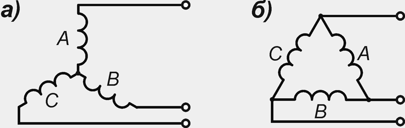
Rice. 4. Connection of windings of phases: a) star; b) a triangle
When the rotor rotates opposite the stator teeth with the phase windings located on them, the north N, then the south S poles of the rotor turn out to be. Magnetic flux F, penetrating the stator windings, changes in magnitude and direction, which, according to Faraday's law, is sufficient for the appearance of an alternating electric voltage at their terminals.
In this case, a variable in magnitude and direction of the EMF will be induced in the phase windings:
E f = 4.44fw k about F,
where f- current frequency, Hz; w- the number of turns of the winding of one phase; kabout- winding coefficient, depending on the number of stator slots per pole and phase; F- magnetic flux;
f = pn / 60, k = z / (2pm),
where z- number of grooves; m- number of phases; p- the number of pole pairs.
In valve generators R usually equal to 6, so the frequency of their alternating current is 10 times less than the rotor speed.
The higher the rotor speed and the greater the value of the magnetic flux, the faster it changes inside the stator phase coils and the higher the voltage induced in them.
Rice. 5. Diagram of a valve generator with a beak-shaped rotor:
1 stator; 2-brush; 3-stator winding; 4-beak poles;
5-excitation winding; 6-contact rings (collector); 7-sleeve
Valve generators with beak-shaped rotor (Fig. 5) are synchronous electric car with built-in semiconductor rectifier. The rotor of an automobile valve generator consists of two pole halves, the protrusions (beaks) 4 of which form the north pole system in one half, and the south pole system in the other. The south poles are located between the north poles, and the field winding 5, put on the steel sleeve 7, is clamped between the pole halves. The beak-shaped design of the rotor makes it possible to form a multi-pole system with one coil. Thus, the rotor is an electromagnet with a rotating alternating electromagnetic field, the magnetomotive force of which is defined as
F = I in W in,
and can be adjusted by changing the excitation current Iv, where Wv- the number of turns of the excitation winding.
Stator package 1 is made up of electrical steel plates to reduce eddy currents. Coils of three-phase winding 3 are placed in the slots of the stator. The increase in the number of slots per pole and phase allows meeting the high requirements for the sinusoidality of the output voltage and efficiency. With the help of slip rings 6 and brushes 2, current is supplied to the field windings Iv to form an alternating magnetic field of the rotor.
In addition, the valve generator (Fig. 6) is equipped with a rectifier unit 3 for rectifying the alternating voltage created in the windings 5 of the stator 4, a pulley 14 for driving the rotor and a fan 13 for cooling the heating windings.

Rice. 6. Alternator:
1-back cover; 2 brushes; 3-diode; 4-stator; 5-stator winding; 6-rolling bearing;
7-collector; 8.9-north and south poles of the electromagnet; 10-rotor winding;
11-front cover; 12 ventilation window; 13-impeller cooling;
14-pulley drive
At present, in the domestic and foreign industry, many different alternators with a beak-shaped rotor are produced (table 1), which satisfy a wide range of requirements imposed on them.
Table 1
The main parameters of some models of generators
Maud.
gen-ra
No-load speed, rpm
Nom. e.g. V ± 0.5
Nom.
current, A
Add. rectifier
Integ.
regu-r
for example
G222
1250
14,3
there is
37-3701
1100
14,1
there is
there is
16.3701
1100
581.3701
1400
13,9
there is
955.3701
1050
14,2
there is
there is
Inductor generators
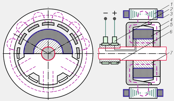
The inductor generator is a non-contact, like-pole synchronous alternating current electric machine with one-sided electromagnetic excitation (Fig. 7). The steel sprocket of the rotor 2 rotates together with the shaft 5, which runs inside the stationary sleeve 8. The excitation winding 7 is fixed on the sleeve, and the stator winding 6 is fixed on the stator teeth. When a direct current passes through the excitation winding, a magnetic flux arises in the magnetic circuit of the generator, lines of force which is shown by the dashed line in Figure 7. The magnetic flux closes through the air gap between the sleeve and the shaft, the rotor sprocket, the working gap between the rotor and the stator, the stator package, the cover on the field coil side and the thick-walled washer or hub flange.

Rice. 7. Diagram of an inductor-type generator:
1-stator magnetic core; 2- rotor (steel sprocket);
3-back cover (the front cover is part of the magnetic circuit);
4-bearing; 5-shaft; 6-stator winding; 7-excitation winding;
8-magnetic inductor system (sleeve with flange); 9-permanent magnet
All sprocket teeth have the same polarity. The change in magnetic flux is associated with a change in the magnetic conductivity of the air gap under the stator teeth. The flux in the stator tooth reaches its maximum value F max(Fig. 8), when the axes of the rotor and stator teeth coincide, and decreases to the minimum value Ф min when the axis of the stator tooth coincides with the axis of the root of the rotor sprocket. Consequently, the magnetic flux in the stator teeth is pulsating and changes only in magnitude without changing direction.

Rice. 8. Change in magnetic flux in the stator tooth over time
For a greater degree of change in the magnetic flux and, therefore, an increase in the power of the generator, permanent magnets are fixed in the cavities of the rotor sprocket. The inductor generator can be single-phase or multi-phase, it depends on the number of phase stator coils, their location and connection method. In three-phase inductor generators, the stator usually has nine teeth with windings.
The winding of each phase can have several coils connected in series, in parallel and mixed. The phases of the stator winding are connected in a multipath star or polygon.
The magnitude of the induced EMF depends on the amplitude of the magnetic flux, the number of turns of the stator winding and the frequency n rotation of the rotor. The more the number of turns, the lower the rotor speed the required voltage can be obtained. The amplitude of the magnetic flux depends on the magnitude of the field current of the field winding.
Currently, the domestic industry produces an inductor generator 955.3701 of alternating current with a fixed axial-longitudinal excitation coil. The generator is equipped with a five-phase stator winding and a five-phase rectifier. The rotor of this generator is made in the form of a six-pointed star made of thin sheets of electrical steel. Permanent magnets are located in the hollows of the star, which contribute to the onset of self-excitation of the generator and somewhat increase its power. Also, in addition to the main excitation winding, this generator has an additional, demagnetizing, winding that neutralizes the effect permanent magnets on high revs generator rotor. The stator winding is located on 10 teeth of the stator magnetic circuit (the pitch of the teeth is 36º) and is divided into five phase sections, two toothed coils in each section. Toothed coils of the same phase section are spaced apart from each other along the perimeter of the stator by 180º.
Other versions of the stator and connection of the phase windings in inductor generators are also possible. But at present, in terms of such parameters as efficiency, weight, dimensions, inductor generators are inferior to generators with slip rings.
Brushless valve generators
Brushless generators are a development based on a generator design with a beak-shaped rotor design (Fig. 9).

Rice. 9. Brushless generator:
a) with air cooled: 1-pulley; 2-fan; 3-front cover; 4-rotating magnetic circuit; 5-stator; 6-fixed excitation winding; 7-shaft; 8-back cover; 9-voltage regulator; 10-diode; 11-mounting bracket; 12-bearing;
b) with liquid cooling: 1-pulley; 2-rectifier; 3-front cover; 4-generator housing; 5-coolant; 6-casing of the cooling jacket; 7-rotor; 8-stator winding; 9-stator; 10-non-magnetic intermediate ring; 11-rotating magnetic circuit (pole); 12-stationary excitation winding; 13-voltage regulator
In generators of this type, only the beak-shaped poles 11 rotate (Fig. 9 b), and the excitation winding 12 remains stationary. One of the pole halves is held against the other by means of a non-magnetic ring 10. The magnetic flux, in addition to the normal working gap, must cross two additional air gaps. Rectifier 2 supplies current to the excitation winding directly through the voltage regulator 13.
The mass of such generators is somewhat greater than that of brush generators with beak-shaped poles of the same power.
Liquid-cooled brushless generators emit less noise due to the lack of a fan, and are capable of integrating with the engine block.
There are also designs of generators with shortened beaks (Fig. 10), which can be obtained constructively if the beak-shaped halves of the pole of the brush generator are pushed apart so that they do not overlap each other and the fastening element 4 (non-magnetic cage) and the electric wires of the field winding are passed into the gap formed 1.

Rice. 10. Schematic of a brushless short-pole valve generator:
1-excitation winding; 2-pole halves with shortened beaks; 3-sleeve;
4-fastening element of the excitation winding; 5-stator; 6-stator winding
The excitation winding is suspended above the steel sleeve 3 between the two pole halves 2. When the generator shaft rotates, only magnetized sprockets rotate, however, the area of their pole pieces is small (compared to brush generators), and due to the lower amplitude of the alternating magnetic flux on the stator teeth , the electric power generated by such a generator will be lower. But the advantage of the design is the small mass of the rotor, which makes it possible to increase the operating speed of the generator, and, consequently, the power it generates.
AC rectification
The alternating current of valve generators is rectified by semiconductor silicon diodes. Diodes have two leads and pass current only from the anode lead to the cathode lead when a positive potential is applied to the anode. In the opposite direction, the diodes do not pass current if the reverse voltage does not exceed the permissible value.
In generator rectifiers, diodes of direct and reverse polarity are used. A diode of direct polarity has a cathode connected to the body, and a diode of reverse polarity has an anode. Depending on the number of phases of the generator, three- and five-phase rectifiers are used.

Rice. 11. Rectification of alternator current:
a) half-wave rectification of single-phase alternating current;
b) full-wave rectification of single-phase alternating current;
c) half-wave rectification of three-phase current;
d) full-wave rectification of three-phase current;
G - generator; VD - rectifier (diode); R is the load; A, B, C - generator phases
According to the shape of the rectified voltage, one- and two-half-wave rectifiers are distinguished. Half-wave single-phase rectifiers G(Fig.11 a) AC is provided by one diode VD which turns on in series with the load R.
For full-wave rectification of a single-phase current, a bridge rectifier of four diodes is assembled VD1 – VD4(Fig. 11 b). The positive half-wave (first half-cycle) of the alternating voltage opens the diodes VD1 and VD4... In the second half cycle, the diodes are open VD2 and VD3... During the entire operation time of the generator with a bridge rectifier to the load R rectified voltage is applied U d one sign.
If one diode is included in each phase of a three-phase valve generator VD1, VD2 and VD3(Fig. 11 c), you can get a half-wave three-phase rectifier. Each rectifier diode only conducts 1/3 of the period when voltage is applied to it in the forward direction.
A full-wave three-phase rectifier has three pairs of diodes - VD1 - VD6(Fig.11 d). One arm of the rectifier is formed by diodes VD1 – VD3 straight polarity, which are connected by cathodes to the positive terminal of the valve generator. Diodes are installed in the second arm of the rectifier VD4 - VD6 reverse polarity. Their anodes are connected to ground. One of the diodes works in the conducting direction VD1, VD2 or VD3, in which the anode has the highest potential, and in the group of diodes VD4 - VD6- the diode with the lowest potential. When in phase A voltage is positive and maximum, and in phases V and WITH the voltages are negative and equal, the current into the load R comes through an open diode VD1 and two diodes VD5 and VD6... If phase voltage A equal to zero, in phase V- positive, and in phase WITH- negative, diodes conduct current VD2 and VD4... The rest of the diodes do not pass current.
Ripple frequency f p rectified full-wave three-phase voltage rectifier U d 6 times the frequency of alternating current.
AC rectification;
Selection of winding data providing the rated voltage at the minimum rotor speed corresponding to the mode idle move engine;
Self-limitation of the strength of the given current.
The main parameters of the valve generator are: rectified voltage U d, rotor speed n and power P(or current strength I d given by the generator at a given voltage).
Rectified voltage dependence U don the strength of the excitation currentI in with off load and constant rotor speed n called idling characteristic (fig. 12). In no-load mode, the rectified voltage is equal to the EMF E d... The idling characteristics of valve generators are obtained when independent excitement.
External characteristics of valve generators are the dependence of the rectified voltage U d(Fig. 12 b) on the strength of the load current I d at a constant rotor speed, voltage at the terminals of the excitation winding and its resistance. With an increase in the load, the rectified voltage drops under the action of the armature reaction, as a result of a decrease in voltage in the stator (armature) circuit and in the rectifier, and the voltage drop in the stator windings is significant and depends on the rotor speed.

Rice. 12. Characteristics of the valve generator:
a) idle; b) external; n max, n Wed, n p, n 0- rotor speed, respectively, maximum, average, calculated and recoil start; U dн- rectified nominal voltage
External characteristics of valve generators are determined by self-excitation and independent excitation. A decrease in voltage with increasing load occurs not only on the active, but also on the inductive resistance of the stator windings. In the case of self-excitation of the valve generator, the voltage drops on the excitation winding itself. The demagnetizing action of the armature reaction reduces the magnetic flux in the working air gap between the rotor and stator.
By family external characteristics the maximum strength of the rectified current is determined I dmax which is created at a given or regulated voltage value.
The speed control characteristic (Fig. 13 a) of the valve generator is the dependence of the excitation current I in on the rotor speed n at constant voltage U gn generator. It is usually determined at several values of the load current.
The minimum excitation current is determined at zero load current and the maximum rotational speed of the generator fan rotor. Speed control characteristics allow you to determine the range of change in the excitation current from the change in load at constant voltage.
With an increase in the rotor speed n and constant load of the valve generator amperage I in excitation should decrease (Fig. 13 a), and with an increase in the strength of the load current - increase (Fig. 13 b).
The generator voltage must be kept constant in the rotor speed range from n 0 before n max in this case, the excitation current will vary from the maximum I bmax to the minimum I вmin values.
The multiplicity of regulation in terms of the excitation current is greater than the multiplicity of regulation in terms of the rotor speed. This is because the magnetization characteristic of the valve generator has a non-linear character, and a deep saturation of the magnetic circuit occurs. The greatest frequency of regulation of the excitation current is possible in the idle mode.
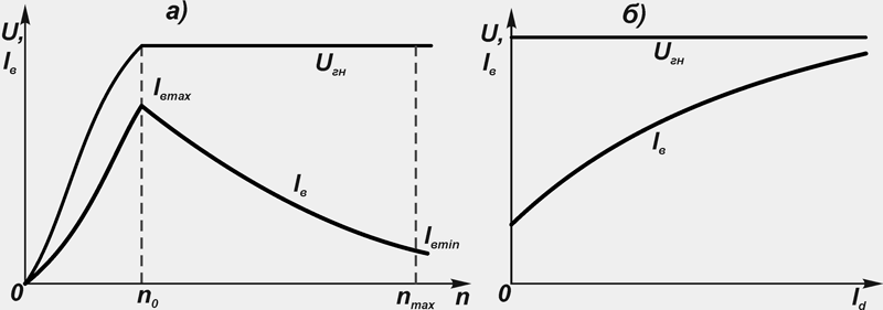
Rice. 13. Dependences of generator voltage and excitation current:
a) on the rotor speed;
b) on the strength of the load current;
U gn- Rated voltage
In connection with the continuous change in the driving mode of the vehicle and, consequently, the rotor speed and the load of the valve generator, the current-speed characteristic of the dependence of the rectified current is important I d, which the valve generator can give to consumers at a given voltage, from the rotor speed n(fig. 14).
The current-speed characteristic is taken at a constant rectified voltage U d = const and direct current excitement I in = const... The control values are the values of the initial frequency n 0 generator recoil, maximum current I dmax at n max... Estimated rotor speeds n p and amperage I dp, are determined at the point of contact of the current-speed characteristic 1 and straight line 2 drawn from the origin. This point corresponds to the maximum value of the ratio of the design power P dp to the calculated rotor speed n p(mode of maximum heating of the valve generator).
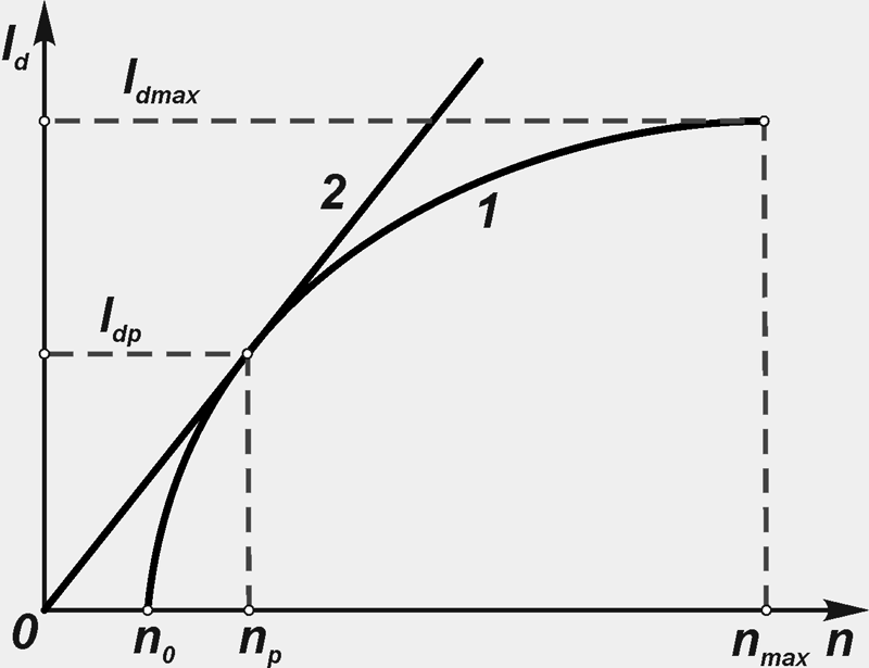
Rice. 14. Current-speed characteristic
The current-speed characteristic is used in the design or selection of a valve generator. It can be determined with independent excitation, self-excitation and operation of a valve generator with a voltage regulator.
All modern car generators have the property of self-limiting maximum current strength. In a wide range of rotor speeds, the current increases slowly, and at the maximum rotor speed it does not exceed the specified maximum value. This is due to the fact that with an increase in the rotor speed of the generator, and, consequently, with an increase in the frequency of the current induced in the stator winding, the inductive resistance of the winding increases, therefore the current increases more slowly, asymptotically tending to a certain limiting value.