Greetings, dear readers. Before dealing with the connection methods and characteristics of the currents of asynchronous motors, it will not be superfluous to remember what it is.
An asynchronous engine is a special type of machine that converts electricity into mechanical energy. The main working principle of such a device is considered to be the following properties. Passing through the stator windings, the alternating current, consisting of three phases, creates the conditions for the appearance of a rotating magnetic field. It is this field that makes the rotor rotate.
Naturally, when connecting the motor, all these factors must be taken into account, because the rotor will rotate in the direction in which the magnetic field rotates. The rotor speed, however, is lower than the driving field speed. By design, these machines are very different (that is, designed to work in different conditions).
Both the operating and starting characteristics of such devices are much superior to the same indicators of single-phase motors.
Any of these motors has two main parts - movable (rotor) and stationary (stator). There are windings on both parts. The difference between them can only be in the type of rotor winding: it can have rotor rings, or be short-circuited. Engines with a squirrel-cage rotor and power up to two hundred kilowatts are connected directly to the network. Motors of higher power must be connected, first, to a reduced voltage and only then switched to the nominal (in order to reduce the starting current by several times).
Asynchronous motor connection
The stator winding of almost any such device has six leads (of which three are the beginning and three are the ends). Depending on what the supply network of the motor is, these leads are connected either in a "star" or in a "triangle". For this purpose, the body of each motor has a box in which the initial and final wires of the windings are brought out (they are designated, respectively, C1, C2, C3 and C4, C5, C6).
Star connection

This is the name of the method of connecting the windings, in which all three windings have one common point (neutral). The line voltage of such a connection is 1.73 times higher than the phase voltage. Positive quality this type of connection is considered to be small starting currents, although the power losses are quite significant.
The delta connection method differs in that with this method, the connection is made in such a way that the end of one winding becomes the beginning of the next.
Delta connection

In this case, the phase and line voltage connections are the same, therefore, with a line voltage of 220 volts, it is the triangle that will be the correct connection of the windings. The positive side of this connection is high power, while the negative side is high starting currents.
To reverse (change the direction of rotation) of a three-phase asynchronous engine, it is enough to swap the terminals of its two phases. In production, this is done using a pair of magnetic starters with dependent switching.
Significant starting currents for induction motors are very undesirable, because they can lead to the effect of a lack of voltage for other types of equipment connected to the same network. This became the reason that by connecting and adjusting motors of this type, there is a problem of minimizing starting currents and increasing the smoothness of starting motors by using specialized equipment. The most effective type of such devices are considered to be soft starters and frequency converters. One of their most valuable qualities is that they are able to maintain the starting current of the motor for quite a long time (usually more than a minute).
In addition to the standard way of turning on asynchronous motors, there are also methods for turning them on into the supply network, which has only one phase.
Capacitor start asynchronous motor
For this, the capacitor switching method is mainly used. The condenser can be installed as one or as a pair (one is starting, and the second is working). A pair of conductors is installed when there is a need to change the capacity during the start-up process, which is done by connecting and disconnecting one of the conductors (starting). For this, as a rule, paper containers are used, since they have no polarity, and when working on alternating current, this is very important.
To calculate the working capacitor, there is the following formula:
The starting capacitor must have a capacity two to three times greater than the operating capacitance and the operating voltage one and a half times higher than the supply voltage.
The starting and operating capacitors are connected in parallel, and so that in parallel with the starting one, a shunt resistance is turned on and one end of the starting capacitor is switched on through the key. When the engine is started, the key is closed, raising the starting current, then it is opened.
However, do not forget that not every engine can be connected to a single-phase network. In addition, the power of the motor in such a connection will be only 0.5-0.6 of the power of a three-phase connection.
Starting currents of an induction motor
Now I will give a table of permissible no-load currents of three-phase motors:
| Electric motor power, kW | No-load current, as a percentage of the nominal, | |||||
| at rotation speed, rpm | ||||||
| 3000 | 1500 | 1000 | 750 | 600 | 500 | |
| 0.12 – 0.55 | 60 | 75 | 85 | 90 | 95 | — |
Before making current measurements on motors, they must be run in (tested on Idling 30-60 minutes - engines with a power of less than 100 kW and from 2 hours, engines whose power is higher than 100 kW). This table is for reference purposes, therefore, real data may differ from these percentages by 10-20.
Motor starting currents can be calculated using the following pair of formulas:
In = 1000Rn / (Un * cosph * √nn),
where Рн is the nominal power of the motor, Un is the nominal value of its voltage, nн is the nominal value of its efficiency.
where In is the current rating, and Kp is the multiplicity direct current to face value (usually indicated in the motor passport).
Write comments, additions to the article, maybe I missed something. Take a look at, I will be glad if you find something else useful on mine. All the best.
Content:When working with various electrical devices, the question often arises of what an inrush current is. In the very simple version the answer will be the current that is consumed when starting an electric motor or other device. Its value can be several times higher than the nominal value required in normal stable operation. Thus, in order to spin the rotor, the electric motor must apply much more energy compared to running at a constant speed. It is possible to reduce inrush currents using special extinguishing systems and soft starters.
Starting currents of electric motors
In every device, device or mechanism, there are processes called starting. This is especially noticeable at the beginning of the movement, when it is necessary to get under way. At this moment, much more effort is required for the initial push than with the further operation of this mechanism.
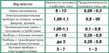
Exactly the same phenomena affect and electrical devices- electric motors, electromagnets, lamps and others. The presence of starting processes in each of them depends on the state of the working elements. For example, the filament of an ordinary light bulb in a cold state has a resistance that is much lower than when heated in operating mode up to 1000 0 C. That is, for a lamp with a power of 100 W, the resistance of the filament during operation will be about 490 the indicator drops to 50 ohms. Therefore, with a high starting current, the bulbs sometimes burn out. They are saved from general burnout by the resistance that increases with heating. Gradually, it reaches a constant value and helps to limit the operating current to the desired value.
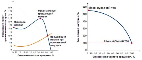
The influence of inrush currents fully affects all types of electric motors, which are widely used in many areas. In order to properly operate electric drives, you need to know their starting characteristics. There are two main parameters that affect the starting current. Glide is the link between the rotor speed and the speed of the electromagnetic field. The slip decreases from 1 to minimum as the speed increases. The starting torque is the second parameter that determines the degree of mechanical stress on the shaft. This load has a maximum value at the moment of starting and becomes nominal after the full acceleration of the mechanism has occurred.
Consideration should be given to the features asynchronous electric motors, which, at start-up, become equivalent to a transformer with a short-circuited secondary winding. It has very little resistance, so the value of the inrush current during a jump can reach many times higher than the nominal value. In the process of further supplying current to the windings, the rotor core begins to gradually saturate with a magnetic field. An EMF of self-induction appears, under the influence of which the inductive resistance of the circuit begins to grow. With the beginning of the rotor rotation, the slip coefficient decreases, that is, the engine acceleration phase begins. With an increase in resistance, the starting current decreases to standard indicators.
During operation, a problem may arise associated with increased inrush currents. The reason for their occurrence, most often, is overheating of electric motors, overloaded electrical networks at the time of start-up, as well as shock mechanical loads in connected devices and mechanisms, such as gearboxes and others. To solve this problem, special devices are provided, represented by frequency converters and soft starters. They are selected taking into account the peculiarities of the operation of a particular electric motor. For example, they are mainly used for units connected to fans. With their help, the starting current is limited to two ratings. This is a completely normal indicator, since during a normal start, the current exceeds the nominal value by 5-10 times. The limitation is achieved by changing the voltage in the windings.
Conventional engines alternating current are widely used in industrial production due to their very simple design and low cost. Their serious drawback is considered to be a difficult start, which is greatly facilitated by frequency converters. The most valuable quality of these devices is their ability to maintain inrush current for one minute or more. The most modern devices allow not only to regulate the start, but also to optimize it according to predetermined operational characteristics.
Battery starting current
The battery is not in vain considered one of the important elements car. Its main function is to supply voltage to existing electrical equipment. This is mainly a starter, lighting and other devices. In order to successfully solve this problem, the battery must not only accumulate, but also preserve the charge for a long time.

One of the main parameters of a battery is the starting current. This value corresponds to the parameters of the current that flows in the starter at the time of its start. The starting current is directly related to the operating mode of the vehicle. If vehicle is used very often, especially in cold conditions, in which case the battery must have a large starting current. Its nominal parameter is usually in accordance with the power of the power supply, provided for 30 seconds at a temperature of minus 18 0 C. It appears at the moment when the key is turned in the ignition lock and the starter starts to work. The current value is measured in amperes.
Starting currents can be completely different for batteries that are the same in their own way outward appearance and basic characteristics. This factor is significantly influenced by the physical properties of materials for manufacturing and design features of each product. For example, an increase in current can be observed if the lead plates become porous, their number increases, orthophosphoric acid is used. The overestimated value of the current does not have a negative effect on the equipment, it only contributes to an increase in the reliability of starting.
The total load current Ia supplied to the motor is calculated using the following formulas:
where
Ia: total current (A)
Pn: rated power (kW)
U: line-to-line voltage for 3-phase motor and voltage between terminals for 1-phase motor (V). 1-phase motors can be connected to phase or line voltage
η: efficiency, i.e. output power (kW) / input power (kW)
cos φ: power factor, i.e. input power (kW) / input power (kVA)
Super transient current and protection setpoint
- The peak value of the overtransient current can be extremely high. Typically this value is 12-15 times the Inm RMS nominal value. Sometimes this value can be 25 times the Inm value.
- The circuit breakers, contactors and thermal relays are designed for motor starting at extremely high super-transient currents (the super-transient peak value can be 19 times the rms nominal value Inm).
- In the event of sudden tripping of overcurrent protection during starting, this means that the starting current is outside the normal range. As a result, the limiting values of the parameters can be reached switchgears, the service life may be shortened and even some devices may be damaged. To avoid such a situation, it is necessary to consider raising the rating of the switchgear.
- Switchgears are designed to provide short-circuit protection for motor starters. Depending on the risk, the tables show combinations of breaker, contactor and thermal relay to provide type 1 or 2 coordination.
Motor starting current
Although the market offers motors with high efficiency, in practice their starting currents are approximately the same as those of standard motors.
The use of delta starters, static soft starters or variable speed drives can reduce the starting current (eg 4 Ia instead of 7.5 Ia).
Compensation of reactive power (kvar) supplied to induction motors
Generally, for technical and financial reasons, it is more advantageous to reduce the current supplied to induction motors. This can be achieved by using capacitors without affecting the power output of the motors.
The application of this principle to optimize the operation of induction motors is called “power factor enhancement” or “reactive power compensation”.
As discussed in the Reactive Power Compensation and Harmonic Filtering chapter, the apparent power (kVA) supplied to the motor can be significantly reduced by using parallel connected capacitors. A decrease in the input apparent power means a corresponding decrease in the input current (since the voltage remains constant).
Reactive power compensation is especially recommended for motors with long periods of operation at reduced power.
As stated above,
![]()
Therefore, decreasing the input apparent power (kVA) results in an increase (i.e., an improvement) in the cos φ value.
The current supplied to the motor after reactive power compensation is calculated by the formula:
![]()
where: cos φ is the power factor before compensation, cos φ 'is the power factor after compensation, Ia is the initial current.
Rice. A4 below shows (depending on the rated motor power) the standard currents for several supply voltages.
| kw | h.p. | 230 V | 380 - 415 B | 400 B | 440 - 480 B | 500 B | 690 B |
|---|---|---|---|---|---|---|---|
| A | A | A | A | A | A | ||
| 0,18 0,25 0,37 |
- - - |
1,0 1,5 1,9 |
- - - |
0,6 0,85 1,1 |
- - - |
0,48 0,68 0,88 |
0,35 0,49 0,64 |
| - 0,55 - |
1/2 - 3/4 |
- 2,6 - |
1,3 - 1,8 |
- 1,5 - |
1,1 - 1,6 |
- 1,2 - |
- 0,87 - |
| - 0,75 1,1 |
1 - - |
- 3,3 4,7 |
2,3 - - |
- 1,9 2,7 |
2,1 - - |
- 1,5 2,2 |
- 1,1 1,6 |
| - - 1,5 |
1-1/2 2 - |
- - 6,3 |
3,3 4,3 - |
- - 3,6 |
3,0 3,4 - |
- - 2,9 |
- - 2,1 |
| 2,2 - 3,0 |
- 3 - |
8,5 - 11,3 |
- 6,1 - |
4,9 - 6,5 |
- 4,8 - |
3,9 - 5,2 |
2,8 - 3,8 |
| 3,7 4 5,5 |
- - - |
- 15 20 |
- 9,7 - |
- 8,5 11,5 |
- 7,6 - |
- 6,8 9,2 |
- 4,9 6,7 |
| - - 7,5 |
7-1/2 10 - |
- - 27 |
14,0 18,0 - |
- - 15,5 |
11,0 14,0 - |
- - 12,4 |
- - 8,9 |
| 11 - - |
- 15 20 |
38,0 - - |
- 27,0 34,0 |
22,0 - - |
- 21,0 27,0 |
17,6 - - |
12,8 - - |
| 15 18,5 - |
- - 25 |
51 61 - |
- - 44 |
39 35 - |
- - 34 |
23 28 - |
17 21 - |
| 22 - - |
- 30 40 |
72 - - |
- 51 66 |
41 - - |
- 40 52 |
33 - - |
24 - - |
| 30 37 - |
- - 50 |
96 115 - |
- - 83 |
55 66 - |
- - 65 |
44 53 - |
32 39 - |
| - 45 55 |
60 - - |
- 140 169 |
103 - - |
- 80 97 |
77 - - |
- 64 78 |
- 47 57 |
| - - 75 |
75 100 - |
- - 230 |
128 165 - |
- - 132 |
96 124 - |
- - 106 |
- - 77 |
| 90 - 110 |
- 125 - |
278 - 340 |
- 208 - |
160 - 195 |
- 156 - |
128 - 156 |
93 - 113 |
| - 132 - |
150 - 200 |
- 400 - |
240 - 320 |
- 230 - |
180 - 240 |
- 184 - |
- 134 - |
| 150 160 185 |
- - - |
- 487 - |
- - - |
- 280 - |
- - - |
- 224 - |
- 162 - |
| - 200 220 |
250 - - |
- 609 - |
403 - - |
- 350 - |
302 - - |
- 280 - |
- 203 - |
| - 250 280 |
300 - - |
- 748 - |
482 - - |
- 430 - |
361 - - |
- 344 - |
- 250 - |
| - - 300 |
350 400 - |
- - - |
560 636 - |
- - - |
414 474 - |
- - - |
- - - |
| 315 - 335 |
- 540 - |
940 - - |
- - - |
540 - - |
- 515 - |
432 - - |
313 - - |
| 355 - 375 |
- 500 - |
1061 - - |
- 786 - |
610 - - |
- 590 - |
488 - - |
354 - - |
| 400 425 450 |
- - - |
1200 - - |
- - - |
690 - - |
- - - |
552 - - |
400 - - |
| 475 500 530 |
- - - |
- 1478 - |
- - - |
- 850 - |
- - - |
- 680 - |
- 493 - |
| 560 600 630 |
- - - |
1652 - 1844 |
- - - |
950 - 1060 |
- - - |
760 - 848 |
551 - 615 |
| 670 710 750 |
- - - |
- 2070 - |
- - - |
- 1190 - |
- - - |
- 952 - |
- 690 - |
| 800 850 900 |
- - - |
2340 - 2640 |
- - - |
1346 - 1518 |
- - - |
1076 - 1214 |
780 - 880 |
| 950 1000 |
- - |
- 2910 |
- - |
- 1673 |
- - |
- 1339 |
- 970 |
Rice. A4: Rated power and currents
The current that is needed to start the electric motor is called the starting current. As a rule, the starting currents of electric motors are several times higher than the currents required to operate in a normally stable mode.
Figure 1. Asynchronous motor A large starting current of an induction motor is necessary in order to spin the rotor from its place, which requires much more energy to be applied than to further maintain a constant number of its revolutions. It is worth noting that, despite a completely different principle of operation, single-phase DC motors are also characterized by high starting currents.
High starting currents of electric motors are undesirable as they can lead to short-term power shortages for other equipment connected to the network (voltage drop). Therefore, when connecting and setting up AC motors (the most common in the industry), the task is always to minimize the values of starting currents, as well as to increase the smooth start of the engine through the use of special additional equipment. Such measures also make it possible to reduce the cost of starting the electric motor (use wires of smaller cross-section, stabilizers and diesel power plants of lower power, etc.).
One of the most effective categories of devices to facilitate harsh starting conditions are soft starters and frequency converters. Their ability to maintain the starting current of AC motors for an extended period of more than a minute is considered especially valuable. Also, the starting current of an induction motor can be reduced by introducing an external resistance into the rotor winding.
Calculation of the starting current of an induction motor
The calculation of the starting current of the electric motor may be required in order to select suitable circuit breakers capable of protecting the switching line of a given electric motor, as well as in order to select the appropriate parameters optional equipment(generators, etc.).
The calculation of the starting current of the electric motor is carried out in several stages:
Determination of the rated current of a three-phase AC motor according to the formula: In = 1000Pn / (Un * cosφ * √ηn). Рн here is the rated power of the motor, Uн is the nominal voltage, and ηн is the nominal efficiency. Cosφ is the nominal power factor of the electric motor. All these data can be found in the technical documentation for the engine.
Calculation of the starting current value according to the formula Istart = In * Kpusk. Here Iн is the nominal current value, and Kpusk acts as a multiple of direct current to the nominal value, which should also be indicated in the technical documentation for the electric motor.
Knowing the exact starting currents of electric motors, you can choose the right circuit breakers that will protect the turn-on line.


