- The coolant (air) temperature sensor converts the engine coolant (air) temperature into voltage direct current.
- The information from the coolant temperature sensor allows you to correct the basic parameters of the engine control, depending on its thermal state.
- The sensor information allows you to correct the basic parameters of the engine control depending on the air temperature in the throttle space of the engine.
- The sensor is a semiconductor zener diode, which is powered by a constant operating current from a stabilized source of the control unit, the output voltage of the sensor changes depending on the ambient temperature. As the temperature rises, the output voltage of the sensor increases.
Sensor design
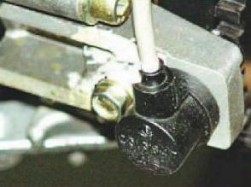
- Structurally, the sensor consists of the following elements:
- metal body of the sensor with a cylindrical head in which the sensing element is located, and middle part with M12x1.5 thread and S19 wrench nut;
- plastic tail with two-pin plug.
Sensor parameters
- Options
- Supply voltage: 5 ... 12V.
- Working current: 0.5 ... 5.0mA.
- Ambient temperature range: -40 ... + 125 ° C.
- Sensor resistance: 24 ... 27 kOhm.
- The sensor has a linear relationship between the output voltage and the ambient temperature.
- The sensitivity of the sensor is 10 mV / ° C.
- Calibration characteristic control points:
- -60 ° C: 2.13 V - calibration violation, circuit failure
- -40 ° C: 2.33V
- -30 ° C: 2.43 V - subcooled motor
- -20 ° C: 2.53V
- 0 ° C: 2.73V
- + 20 ° C: 2.93 V— cold engine
- + 40 ° C: 3.13 V
- + 70 ° C: 3.43 V — hot engine
- + 80 ° C: 3.53 V
- + 90 ° C: 3.63 V
- + 105 ° C: 3.83 V - overheated motor
- + 125 ° C: 2.93 V — violation of calibration, circuit failure
Installing and mounting the sensor on a car
- Temperature sensors are installed on the engine.
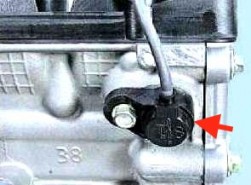
- The coolant temperature sensor is usually installed on the thermostat housing of the engine block.
- The air temperature sensor is installed on the receiver of the intake pipe of the engine:
- for ZMZ-409.10, ZMZ-4062.10, ZMZ-405.10 — right, bottom;
- for UMZ-4213.10, UMZ-420.10 — on the left, in front.
- The sensor is installed by screwing it into the threaded bore. The connection is sealed with a sealant.
- The sensor is connected to the wiring harness using a two-pin latching socket.
- The sensors are polar according to the switching circuit, that is, the reverse switching on of the sensor is equivalent to its breakage state.
Sensor analogs
There are no analogs of the temperature sensor 19.3828 (Kaluga, JSC AVTOPRIBOR).
External manifestations of faults in the sensor circuits

- Increased speed idle move hot engine. The malfunction lamp is on when the engine is running. Self-diagnostics of the unit fixes fault codes 21 or 22.
- Check the integrity of connections 45 and 30d of the coolant temperature sensor.
- The malfunction lamp is on when the ignition is turned on. Self-diagnostics of the unit fixes fault codes 17 or 18.
- Check the integrity of connections 44 and 30v of the air temperature sensor.
- A cold engine will not start (it will not start well). The malfunction lamp is off (no system malfunctions).
- The calibration of the coolant temperature sensor is broken. Check the calibration and replace the sensor.
- Increased detonation of a hot engine. The malfunction lamp is off (no system malfunctions).
- The calibration of the air temperature sensor is broken. Check the calibration and replace the sensor.
The engine control system ZMZ-409 uses two identical temperature sensors 19.3828 - a coolant temperature sensor and an air temperature sensor. Checking the serviceability of temperature sensors, as a rule, is carried out in cases of difficulty in starting the engine or if it is impossible.
The temperature sensor is a semiconductor zener diode, which is powered by a constant operating current from a stabilized source of the control unit. The output voltage of the sensor changes depending on the ambient temperature. As the temperature rises, the output voltage of the sensor increases. Both sensors are the same and polar according to the connection scheme, that is, their reverse connection is equivalent to an open circuit condition.
Sensor 19.3828 coolant temperature.
Installed in the thermostat housing and connected to the controller input connected to an internal 5 Volt source through a 2 kΩ resistor. The information from this sensor allows you to correct the basic parameters of the engine control, depending on its thermal state, since the coolant temperature affects most of the characteristics that it controls.
The electronic engine control unit ZMZ-409 calculates the coolant temperature by the voltage drop across the sensor. On a cold engine, the voltage drop is high, on a warm one - low.
Air temperature sensor 19.3828.
A full check of the health of the temperature sensors is carried out using electrical circuit shown in the figure below. Before starting the test with a variable resistor using a milliammeter, it is necessary to set the current in the circuit in the range from 1 to 1.5 mA. To change the temperature of the sensor's sensitive element, you can use a container with water heated to the boiling point, having previously installed a thermometer in it.

Having lowered the sensor into a container with boiling water, as it cools down, the voltage readings of the sensor are taken with a voltmeter. Control measurements are made at temperatures plus 100, 90, 80, 60, 40 and 20 degrees. For a working temperature sensor, the voltage in the circuit should be close to the following values:
20 - 2.93 Volts
+40 - 3.13 Volts
+60 - 3.33 Volts
+80 - 3.53 Volts
+90 - 3.63 Volts
+100 - 3.73 Volts
External manifestations of malfunctions of the coolant temperature sensor when the ZMZ-409 engine is running.
It is difficult to start the engine, it is necessary to warm up the engine by maintaining the speed with the gas pedal, on a warmed-up engine, the idle speed is increased. The lamp is on Check Engine malfunctions in the control system, the control unit issues the following malfunctions:
Mikas 7.2
021 - low level of the coolant temperature sensor signal.
022 - high level of the coolant temperature sensor signal.
Mikas 11 and Bosch ME17.9.7
0116 - Coolant temperature sensor signal output out of range.
0117 - Low level coolant temperature sensor circuit signal.
0118 - High level of the signal of the coolant temperature sensor circuit.
If a cold engine does not start at all or is difficult to start, but the malfunction lamp in the control system does not light up, and the self-diagnosis system does not issue any error codes, then the calibration of the coolant temperature sensor may be violated, it must be checked and, if necessary, replaced.
External manifestations of malfunctions of the air temperature sensor when the ZMZ-409 engine is running.
It is necessary to check the serviceability of the air temperature sensor circuits if the warning lamp is on when the ignition is turned on Check faults Engine, and the control unit system generates the following faults:
Mikas 7.2
017 - low level of the air temperature sensor signal.
018 - high level of the air temperature sensor signal.
Mikas 11 and Bosch ME17.9.7
0112 - Low signal level of the air temperature sensor circuit.
0113 - High signal level of the air temperature sensor circuit.
If the Check Engine lamp does not light up, the self-diagnosis system does not issue error codes, but at the same time there is increased detonation on a warm engine, then the calibration of the air temperature sensor may be violated, if the check has confirmed this, then the sensor must be replaced.
Page 1 of 3
Integrated microprocessor engine control system ZMZ-40524
Microprocessor control system gasoline engine internal combustion ZMZ-40524.10 is intended for:
To ensure optimal engine operation in all modes, taking into account fuel efficiency, emissions of toxic substances in exhaust gases, starting and driving qualities of the car;
For automated monitoring of the technical condition of the engine and control system elements responsible for compliance with toxicity standards, as well as for external diagnostics in accordance with the requirements of EOBD (European On-board Diagnostics - European On-Board Diagnostics).
A feature of the engine control system ZMZ-40524 is:
The use of a throttle module with an electric motor, which allows you to adjust the position throttle electronically to obtain the optimal mixture and the required characteristics of the flow of torque on the car;
The use of a drainage fuel line, complete with injectors with a working pressure in the line (400 ± 8 kPa), to reduce the vaporization of gasoline vapors.
The use of individual ignition coils to reduce the level of interference;
Implementation of the EOBB on-board European diagnostics system, which controls technical condition system components responsible for exceeding the limit values of harmful substances in the exhaust gases of the vehicle.
Sensors and control system units located on the engine
Synchronization sensor(provisions crankshaft engine) DG-6K0 261 210 302 Bosch (40904.3847010) or similar, inductive type, located on the chain cover near the crankshaft pulley.
|
R |
 is. 2
is. 2Generates an electrical signal when the magnetic field of the sensor interacts with a special toothed disk (60-2 teeth) mounted on the crankshaft pulley. The mutual orientation of the synchronization disk and the sensor is such that the moment the sensor axis passes the twentieth tooth of the synchronization disk corresponds to the position of the piston of the first and fourth cylinders at top dead center. The reading of the tooth number is from the pass in the direction opposite to the rotation of the engine crankshaft.
The sensor is designed to determine the angular position and speed of the engine crankshaft by the control unit.
Phase sensor(provisions camshaft) PG-3.8 0232103048 Bosch (40904.3847000) or similar, Hall effect, located on the cylinder head. Generates a signal when the magnetic field of the sensor interacts with a marker (bent plate) installed on the exhaust camshaft.
|
|
 Rice. 3
The moment the signal is formed by the phase sensor, if there is a coincidence of the run of the first tooth of the disc 60-2 with the axis of the synchronization sensor, indicates the beginning of the compression stroke in the first cylinder. The reading of the tooth number is from the gap in the direction opposite to the rotation of the engine crankshaft (see the crankshaft position sensor).
The phase sensor is designed to determine the phase of the operating cycle in the engine cylinders by the control unit.
Electric throttle module with throttle position sensor ETB TS A2C5 330 £ 30 Siemens (40624.1148090).
Drive - DC motor with voltage on-board network, damper position sensor - magnetoresistive (two-channel).
The throttle module is located on the intake pipe.
The throttle module is designed to control the filling of the engine cylinders with air during start-up, warm-up, idle, when external power consumers are turned on / off, at various loads - in order to optimize the torque.
The sensor is designed to determine the angular position of the throttle by the control unit.
Coolant temperature sensor(engine temperature condition)
TF-W0 280 130 093 Bosch or similar, (40904.3828000). The sensor is located on the thermostat housing.
The sensor is designed to measure the engine coolant temperature by the control unit.
Ignition coils (fig. 7) ZS-K-1x1 0 221 504 027 Bosch (40904.3705000) or similar, individual, four, transformer type, mounted on the valve cover.
Designed to generate high voltage energy for spark plugs.
Fuel rail (fig. 9)(fuel distribution line) with electromagnetic injectors ZMZ6354 (DEKA1D) Siemens assembled (40624.1100010 *).
Placement on the inlet pipe. The ramp is non-draining, steel, with a fitting for a quick-disconnect connection.
The fuel rail is designed to supply fuel to the engine cylinders.