I was one of the first to assemble an amplifier based on the TDA7294 according to the circuit proposed by the manufacturer.

At the same time, I was not very happy with the quality of sound reproduction, especially in the high frequencies. On the Internet, my attention was drawn to the LINCOR article posted on the website datagor.ru. The author's rave reviews about the sound of the UMZCH on the TDA7294, assembled using a voltage-controlled current source (VCS) circuit, intrigued me. As a result, I assembled the UMZCH according to the following scheme.

The scheme works as follows. The signal from the IN input is fed through the pass capacitor C1 to the low-impedance arm feedback R1 R3, which together with capacitor C2 forms a low-pass filter that prevents interference and high-frequency noise from penetrating into the audio path. Together with resistor R4, the input circuit creates the first OOS segment, Ku of which is equal to 2.34. Further, if not for the current sensor R7, the gain of the second circuit would be set by the ratio R5/R6 and would be equal to 45.5. Final Ku would be about 100. However, there is still a current sensor in the circuit, and its signal, summed with the voltage drop across R6, creates a partial negative feedback on the current. With our circuit ratings Ku=15.5.
Amplifier characteristics when operating at a 4 Ohm load:
– Operating frequency range (Hz) – 20-20000;
– Supply voltage (V) – ±30;
– Nominal input voltage (V) – 0.6;
– Nominal output power (W) – 73;
– Input resistance (kOhm) – 9.4;
– THD at 60W, no more (%) – 0.01.
A 12V parametric stabilizer is installed on the printed circuit board to power service circuits 9 and 10 of the TDA7294, shown in the figure.

In the “Play!” position, the amplifier is in an unlocked state and is ready for use every second. In the “Mute” position, the input and output stages of the microcircuit are blocked, and its consumption is reduced to the minimum standby currents. The capacitances of C11 and C12 are doubled compared to standard ones to provide greater turn-on delay and prevent clicking in the speakers even when charging the power supply capacitors for a long time.
Amplifier parts
All resistors, except R7 and R8, are carbon or metal film 0.125–0.25 W, type C1-4, C2-23 or MLT-0.25. Resistor R7 is a 5W wirewound resistor. White SQP resistors in ceramic housing are recommended. R8 – Zobel circuit resistor, carbon, wire or metal film 2W.
C1 – film, the highest available quality, lavsan or polypropylene. K73-17 at 63V will also give a satisfactory result. C2 – ceramic disk or any other type, for example K10–17B. C3 - electrolyte of the highest available quality for a voltage of at least 35 V, C4 C7, C8, C9 - film type K73-17 for 63 V. C5 C6 - electrolytic for a voltage of at least 50 V. C11 C12 - any electrolytic for a voltage of at least 25 V. D1 – any 12…15 V zener diode with a power of at least 0.5 W. Instead of the TDA7294 chip, you can use TDA7296...7293. In the case of using TDA7296, TDA7295, TDA7293, it is necessary to bite off or bend and not solder the 5th leg of the microcircuit.
Both output terminals of the amplifier are “hot”, neither of them is grounded, because acoustic system is also a feedback link. The speaker is switched on between and .
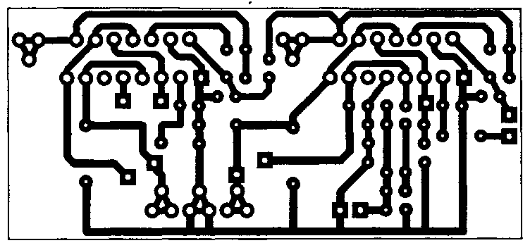
Below is a board layout with views from the elements and conductors, created using the Sprint-Layout_6.0 program.
Low frequency power amplifier Hi-Fi class, made using a bridge circuit using two TDA7294 integrated circuits. Allows you to get up to 170 watts of output power, perfect for a subwoofer.
Specifications
- Output power at 8 Ohm load and power supply ±25V - 150 W;
- Output power at 16 Ohm load and ±35V power supply - 170 W.
Schematic diagram
The amplifier has short circuit protection for the output stage, thermal protection (switching to reduced power in case of overheating that occurs under heavy loads), surge protection, a shutdown mode (Standby), an input signal on/off mode (Mute), and protection from a “click” when turning on/off. All this has already been implemented in TDA7294 integrated circuits.
Rice. 1. Bridge circuit for connecting two TDA7294 microcircuits - a powerful bridge low-frequency amplifier.
Parts and PCB
Rice. 2. Printed circuit board for the bridge version of the inclusion of TDA7294 microcircuits.

Rice. 3. Location of components for the bridge version of the inclusion of TDA7294 microcircuits.
To power such a power amplifier, you need a power source with a transformer with a power of at least 250-300 watts. In the rectifier circuit, it is advisable to install electrolytic capacitors of 10,000 μF or more on each arm.
Bridge circuit from the datasheet

Rice. 4. Bridge circuit for connecting two TDA7294 microcircuits (from the datasheet).
In bridge mode, the load resistance must be at least 8 ohms, otherwise the microcircuits will burn out from overcurrent!
Printed circuit board
Universal printed circuit board for two-channel and bridged power amplifier options.
Bridge circuit turning on the UMZCH- these are two identical channels, in one of which the signal input is connected to ground, and the feedback input (leg 2) is connected through a 22K resistor to the output of the second channel.
Also, the 10th legs of the microcircuits (Mute) and the 9th legs (Stand-By) need to be connected to a mode control circuit assembled using resistors and capacitors (Figure 6).

Rice. 5. Printed circuit board for a power amplifier based on TDA7294 chips.
There are slight deviations in the boards (in better side) from the diagram from the datasheet:
- At the inputs of the microcircuits (pin 3), 4 µF capacitors are installed, not 0.56 µF;
- A 470 µF capacitor is connected between the 680 Ohm resistor (which goes to pin 2) and ground;
- The capacitors between legs 6 and 14 are 470 µF, not 22 µF;
- For power supply, instead of 0.22 µF capacitors, it is proposed to install 680 nF (0.68 µF);
In a bridge connection, pins 10 and 9 are connected together respectively and connected to the mode control circuit.

Rice. 6. Simple scheme control of Standby-Mute modes for TDA7294 chips.
To turn on the microcircuits (take them out of quiet and energy-saving modes), the “VM” and “VSTBY” contacts just need to be connected to the positive +Vs power supply pin.
This printed circuit board is universal; it can be used for both dual-channel and bridge modes of operation of the amplifier on TDA7294 chips. The ground wiring (GND) is very well done here, which will improve the reliability and noise immunity of the UMZCH.
Literature:
- Datasheet for the TDA7294 chip - Download (7-Zip archive, 1.2MB).
- FAQ for TDA7294 - cxem.net/sound/amps/amp129.php
Author of the article: Novik P.E.
Introduction
Designing an amplifier has always been a challenging task. Fortunately, recently, many integrated solutions have appeared that make life easier for amateur designers. I, too, did not complicate the task for myself and chose the simplest, high-quality, with a small number of parts, does not require configuration and stable operation of the amplifier on the TDA7294 chip from SGS-THOMSON MICROELECTRONICS. Recently, complaints about this microcircuit have spread on the Internet, which were expressed approximately as follows: “spontaneously excites if the wiring is incorrect; it burns for any reason, etc.” Nothing like this. It can only be burned by improper switching on or short circuiting, and cases of excitation have never been noticed, and not just by me. In addition, it has internal protection against short circuits in the load and protection against overheating. It also includes a muting function (used to prevent clicking when turned on) and a standby function (when there is no signal). This IC is a class AB ULF. One of the main features of this chip is the use field effect transistors in the preliminary and output amplification stages. Its advantages include high output power (up to 100 W at a load with a resistance of 4 Ohms), the ability to operate in a wide range of supply voltages, high specifications (small distortion, low level
noise, wide range of operating frequencies, etc.), minimum required external components and low cost
Main characteristics of TDA7294: |
Parameter |
Conditions |
Minimum | Typical | Maximum |
| Units | Supply voltage | ±10 | ±40 | ||
| IN | Frequency range 3db signal |
20-20000 | Output power 1W | ||
| Hz | Long-term power output (RMS) harmonic coefficient 0.5%: Up = ± 35 V, Rн = 8 Ohm Up = ± 31 V, Rн = 6 Ohm |
60 60 60 |
70 70 70 |
Up = ± 27 V, Rн = 4 Ohm | |
| W | Peak music output power (RMS), duration 1 sec. harmonic factor 10%: Up = ± 38 V, Rн = 8 Ohm Up = ± 33 V, Rн = 6 Ohm |
100 100 100 |
Up = ± 27 V, Rн = 4 Ohm | ||
| Up = ± 29 V, Rн = 4 Ohm | Total harmonic distortion Po = 5W; 1kHz |
0,005 |
0,1 |
% | |
| Po = 0.1-50W; 20-20000Hz Up = ± 27 V, Rн = 4 Ohm: Po = 5W; 1kHz |
0,01 |
% | |||
| Po = 5W; 1kHz | 145 | Protection response temperature | |||
| 0 C | 20 | 30 | 60 | Quiescent current | |
| mA | 100 | Input impedance | |||
| kOhm | 24 | 30 | 40 | Voltage Gain | |
| dB | 10 | Peak output current | |||
| A | 0 | 70 | Protection response temperature | ||
| Operating temperature range | 1,5 | Case thermal resistance | |||
0 C/W
(PDF format).
There are quite a lot of circuits for connecting this microcircuit, I will consider the simplest one:
Typical connection diagram:
| List of elements: | Position | Name | Type |
| Quantity | C1 | 0.47 µF | 1 |
| C2, C4, C5, C10 | 22 µF x 50 V | K50-35 | 4 |
| C3 | 100 pF | 1 | |
| C6, C7 | 220 µF x 50 V | K50-35 | 2 |
| C8, C9 | 0.1 µF | 0.47 µF | 2 |
| DA1 | TDA7294 | 1 | |
| R1 | 680 Ohm | MLT-0.25 | 1 |
| R2…R4 | 22 kOhm | MLT-0.25 | 3 |
| R5 | 10 kOhm | MLT-0.25 | 1 |
| R6 | 47 kOhm | MLT-0.25 | 1 |
| R7 | 15 kOhm | MLT-0.25 | 1 |
The microcircuit must be installed on a radiator with an area of >600 cm 2 . Be careful, on the microcircuit body there is not a common one, but a power minus! When installing the microcircuit on a radiator, it is better to use thermal paste. It is advisable to place a dielectric (mica, for example) between the microcircuit and the radiator. The first time I didn’t attach any importance to this, I thought, why would I be so frightened that I would short the radiator to the case, but in the process of debugging the design, tweezers that accidentally fell from the table shorted the radiator to the case. The explosion was awesome! The microcircuits were simply blown to pieces! In general, I got off with a slight fright and $10 :). On the board with the amplifier, it is also advisable to supply powerful electrolytes 10,000 microns x 50V, so that during power peaks the wires from the power supply do not cause voltage dips. In general, the larger the capacitance of the capacitors on the power supply, the better, as they say, “you can’t spoil the porridge with butter.” Capacitor C3 can be removed (or not installed), which is what I did. As it turned out, it was precisely because of it that when a volume control (a simple variable resistor) was turned on in front of the amplifier, an RC circuit was obtained, which, when the volume increased, mowed down the high frequencies, but in general it was needed to prevent excitation of the amplifier when ultrasound was applied to the input. Instead of C6, C7, I put 10000mk x 50V on the board, C8, C9 can be installed of any similar value - these are power filters, they can be in the power supply, or you can solder them by surface mounting, which is what I did.
Pay:
I personally don’t really like using ready-made boards, for one simple reason - it’s difficult to find elements exactly the same size. But in an amplifier, the wiring can greatly affect the sound quality, so it's up to you to decide which board to choose. Since I assembled an amplifier for 5-6 channels at once, therefore the board for 3 channels at once:

In vector format (Corel Draw 12)
Amplifier power supply, low pass filter, etc.
power unit
For some reason, the amplifier's power supply raises many questions. In fact, right here, everything is quite simple. A transformer, diode bridge and capacitors are the main elements of the power supply. This is enough to assemble the simple block nutrition.

To power a power amplifier, voltage stabilization is not important, but the capacitance of the power supply capacitors is important, the larger the better.
My power supply is implemented according to the following scheme:

The +-15V power supply is intended to power operational amplifiers in the amplifier's preliminary stages. You can do without additional windings and diode bridges by powering the stabilization module from 40V, but the stabilizer will have to suppress a very large voltage drop, which will lead to significant heating of the stabilizer microcircuits. Stabilizer chips 7805/7905 are imported analogues of our KREN.
Variations of blocks A1 and A2 are possible:

Block A1 is a filter for suppressing power supply noise.
Block A2 is a block of stabilized voltages +-15V. First Alternative option- easy to implement, for powering low-current sources, the second is a high-quality stabilizer, but requires precise selection components (resistors), otherwise you will get a misalignment of the “+” and “-” arms, which will then result in a zero misalignment on the operational amplifiers.
Transformer
Power supply transformer for stereo amplifier at 100W it should be approximately 200W. Since I was making an amplifier for 5 channels, I needed a more powerful transformer. But I didn’t need to pump out all 100W, and all channels cannot simultaneously draw power. I came across a TESLA transformer on the market (below in the photo) 250 watts - 4 windings of 1.5 mm wire of 17V each and 4 windings of 6.3V each. By connecting them in series, I got the required voltages, although I had to rewind the two 17V windings a little in order to get the total voltage of the two windings ~27-30V, since the windings were on top - it wasn’t too difficult.
An excellent thing is a toroidal transformer, these are used to power halogen lamps, there are plenty of them in markets and stores. If two such transformers are structurally placed one on top of the other, the radiation will be mutually compensated, which will reduce interference to the amplifier elements. The trouble is that they have one 12V winding. In our radio market you can make such a transformer to order, but this pleasure will cost a lot. In principle, you can buy 2 transformers for 100-150 Watt and rewind the secondary windings; the number of turns of the secondary winding will need to be increased by about 2-2.4 times.
Diodes / diode bridges
You can buy imported diode assemblies with a current of 8-12A, this greatly simplifies the design. I used KD 213 pulse diodes, and I made a separate bridge for each arm to provide a current reserve for the diodes. When turned on, powerful capacitors are charged, and the current surge is very significant; at a voltage of 40 V and a capacitance of 10,000 μF, the charging current of such a capacitor is ~10 A, respectively, 20 A across two arms. In this case, the transformer and rectifier diodes operate briefly in short circuit mode. Current breakdown of diodes will have unpleasant consequences. The diodes were installed on the radiators, but I did not detect heating of the diodes themselves - the radiators were cold. To eliminate power supply interference, it is recommended to install a ~0.33 µF capacitor, type K73-17, in parallel with each diode in the bridge. I really didn't do this. In the +-15V circuit, you can use bridges of the KTs405 type, for a current of 1-2A.
Design


Ready design.
The most boring activity is the body. For the case, I took an old slim case from a personal computer. I had to shorten it a little in depth, although it was not easy. I think that the case turned out to be successful - the power supply is in a separate compartment and you can freely put 3 more amplification channels into the case.

After field tests, it turned out that it would be useful to install fans to blow over the radiators, despite the fact that the radiators are quite impressive in size. I had to make holes in the case from the bottom and top for good ventilation. Fans are connected via 100 Ohm trim resistor 1W at the lowest speed (see next figure).
Amplifier block

The microcircuits are based on mica and thermal paste, the screws also need to be insulated. The radiators and the board are screwed to the case through dielectric racks.

Input circuits
I really wanted not to do this, only in the hope that it was all temporary....

After hanging these guts, a slight hum appeared in the speakers, apparently something was wrong with the “ground”. I dream of the day when I throw it all out of the amp and use it only as a power amp.
Adder board, low pass filter, phase shifter

Regulation block

Result
It turned out more beautiful from the back, even if you turned it butt forward... :)

Construction cost.
| TDA 7294 | $25,00 |
| capacitors (power electrolytes) | $15,00 |
| capacitors (others) | $15,00 |
| connectors | $8,00 |
| power button | $1,00 |
| diodes | $0,50 |
| transformer | $10,50 |
| radiators with coolers | $40,00 |
| resistors | $3,00 |
| variable resistors + knobs | $10,00 |
| biscuit | $5,00 |
| frame | $5,00 |
| operational amplifiers | $4,00 |
| Surge Protectors | $2,00 |
| Total | $144,00 |
Yes, it didn't come cheap. Most likely I didn’t take something into account, I just bought, as always, much more of everything, because I still had to experiment, and I burned 2 microcircuits and exploded one powerful electrolyte (I didn’t take all this into account). This is a calculation for an amplifier for 5 channels.
As you can see, the radiators turned out to be very expensive; I used inexpensive but massive processor coolers; at that time (a year and a half ago) they were very good for cooling processors. If you consider that an entry-level receiver can be bought for $240, then you may wonder whether you need it :), although it contains an amplifier of a lower quality. Amplifiers of this class cost about $500.
| List of radioelements | Name | Designation | Type | Denomination | Note | Shop |
|---|---|---|---|---|---|---|
| My notepad | DA1 | TDA7294 | 1 | Audio amplifier | ||
| To notepad | C1 | Capacitor | 1 | 0.47 µF | Audio amplifier | |
| 0.47 µF | 22 µF x 50 V | 4 | C2, C4, C5, C10 | Audio amplifier | ||
| K50-35 | C1 | 100 pF | 1 | Audio amplifier | ||
| C3 | C6, C7 | 220 µF x 50 V | 2 | C2, C4, C5, C10 | Audio amplifier | |
| Electrolytic capacitor | C1 | C8, C9 | 2 | 0.47 µF | Audio amplifier | |
| 0.1 µF | R1 | 680 Ohm | 1 | Resistor | Audio amplifier | |
| MLT-0.25 | R1 | 22 kOhm | 3 | Resistor | Audio amplifier | |
| R2-R4 | R1 |
R5
Updated: 04/27/2016 An excellent amplifier for home can be assembled using the TDA7294 chip. If you are not strong in electronics, then such an amplifier perfect option
, it does not require fine-tuning and debugging like a transistor amplifier and is easy to build, unlike a tube amplifier.
The TDA7294 microcircuit has been in production for 20 years and has still not lost its relevance and is still in demand among radio amateurs. For a novice radio amateur, this article will be a good help in getting to know integrated audio amplifiers.
In this article I will try to describe in detail the design of the amplifier on the TDA7294. I will focus on a stereo amplifier assembled according to the usual circuit (1 microcircuit per channel) and will briefly talk about the bridge circuit (2 microcircuits per channel).
TDA7294 chip and its features
TDA7294 is the brainchild of SGS-THOMSON Microelectronics, this chip is an AB class low-frequency amplifier, and is built on field-effect transistors.
- The advantages of the TDA7294 include the following:
- output power, with distortion 0.3–0.8%:
- 70 W for 4 ohm load, conventional circuit;
- 120 W for 8 ohm load, bridge circuit;
- Mute function and Stand-By function;
Specifications
| low noise level, low distortion, frequency range 20–20000 Hz, wide operating voltage range - ±10–40 V. | |||||
|---|---|---|---|---|---|
| Main characteristics of TDA7294: | Parameter | Conditions | Minimum | Typical | Maximum |
| Units | Supply voltage | ±10 | ±40 | ||
| IN | Technical characteristics of the TDA7294 chip Signal 3 db |
20-20000 | Output power 1W | ||
| Hz | Long-term power output (RMS) Output power 1W Up = ±35 V, Rн = 8 Ohm Up = ±31 V, Rн = 6 Ohm |
60 60 60 |
70 70 70 |
Up = ± 27 V, Rн = 4 Ohm | |
| W | Peak music output power (RMS), duration 1 sec. Up = ±27 V, Rн = 4 Ohm Up = ±38 V, Rн = 8 Ohm Up = ±29 V, Rн = 4 Ohm |
100 100 100 |
Up = ± 27 V, Rн = 4 Ohm | ||
| Up = ± 29 V, Rн = 4 Ohm | Total harmonic distortion Po = 0.1–50W; 20–20000Hz |
0,005 | 0,1 | % | |
| Up = ±27 V, Rн = 4 Ohm: Total harmonic distortion Po = 0.1–50W; 20–20000Hz |
0,01 | 0,1 | % | ||
| Po = 5W; 1kHz | 145 | °C | |||
| 0 C | 20 | 30 | 60 | Quiescent current | |
| mA | 100 | Input impedance | |||
| kOhm | 24 | 30 | 40 | Voltage Gain | |
| dB | 10 | Peak output current | |||
| A | 0 | 70 | °C | ||
| Operating temperature range | 1,5 | °C/W | |||
Pin assignment
| Pin assignment of the TDA7294 chip | |||
|---|---|---|---|
| IC output | List of radioelements | Purpose | Connection |
| 1 | Stby-GND | "Signal Ground" | "General" |
| 2 | In- | Inverting input | Feedback |
| 3 | In+ | Non-inverting input | Audio input via coupling capacitor |
| 4 | In+Mute | "Signal Ground" | "General" |
| 5 | N.C. | Not used | – |
| 6 | Bootstrap | "Voltage boost" | C1 |
| 7 | +Vs | Input stage power supply (+) | |
| 8 | -Vs | Input stage power supply (-) | |
| 9 | Stby | Standby mode | Control block |
| 10 | Mute | Mute mode | |
| 11 | N.C. | Not used | – |
| 12 | N.C. | Not used | – |
| 13 | +PwVs | Output stage power supply (+) | Positive terminal (+) of the power supply |
| 14 | Out | Exit | Audio output |
| 15 | -PwVs | Output stage power supply (-) | Negative terminal (-) of the power supply |
Note. The microcircuit body is connected to the power supply negative (pins 8 and 15). Do not forget about insulating the radiator from the amplifier body or insulating the microcircuit from the radiator by installing it through a thermal pad.
I also want to note that in my circuit (as well as in the datasheet) there is no separation of input and output lands. Therefore, in the description and in the diagram, the definitions of “general”, “ground”, “housing”, GND should be perceived as concepts of the same sense.
The difference is in the cases
The TDA7294 chip is available in two types - V (vertical) and HS (horizontal). The TDA7294V, having a classic vertical body design, was the first to roll off the production line and is still the most common and affordable.

Complex of protections
The TDA7294 chip has a number of protections:
- protection against power surges;
- protection of the output stage from short circuit or overload;
- thermal protection. When the microcircuit heats up to 145 °C, the Mute mode is activated, and at 150 °C the Stand-By mode is activated;
- protection of microcircuit pins from electrostatic discharges.
Power amplifier on TDA7294
A minimum of parts in the harness, a simple printed circuit board, patience and known good parts will allow you to easily assemble an inexpensive TDA7294 UMZCH with clear sound and good power for home use.
You can connect this amplifier directly to the line output of your computer sound card, because The nominal input voltage of the amplifier is 700 mV. And the nominal voltage level of the linear output of the sound card is regulated within 0.7–2 V.
Amplifier block diagram

The diagram shows a version of a stereo amplifier. The structure of the amplifier using a bridge circuit is similar - there are also two boards with TDA7294.
- A0. power unit
- A1. Control unit for Mute and Stand-By modes
- A2. UMZCH (left channel)
- A3. UMZCH (right channel)
Pay attention to the connection of the blocks. Improper wiring inside the amplifier may cause additional interference. To minimize noise as much as possible, follow several rules:
- Power must be supplied to each amplifier board using a separate harness.
- The power wires must be twisted into a braid (harness). This will compensate magnetic fields created by current flowing through conductors. We take three wires (“+”, “-”, “Common”) and weave them into a pigtail with a slight tension.
- Avoid ground loops. This is a situation where a common conductor, connecting blocks, forms a closed circuit (loop). The connection of the common wire must go in series from the input connectors to the volume control, from it to the UMZCH board and then to the output connectors. It is advisable to use connectors isolated from the housing. And for input circuits also shielded wires in insulation.
List of parts for TDA7294 power supply:

When purchasing a transformer, please note that the effective voltage value is written on it - U D, and by measuring it with a voltmeter you will also see the effective value. At the output after the rectifier bridge, the capacitors are charged to the amplitude voltage - U A. The amplitude and effective voltages are related by the following relationship:
U A = 1.41 × U D
According to the characteristics of the TDA7294, for a load with a resistance of 4 Ohms, the optimal supply voltage is ±27 volts (U A). The output power at this voltage will be 70 W. This is the optimal power for the TDA7294 - the distortion level will be 0.3–0.8%. There is no point in increasing the power supply to increase power because... the level of distortion increases like an avalanche (see graph).

We calculate the required voltage of each secondary winding of the transformer:
U D = 27 ÷ 1.41 ≈ 19 V
I have a transformer with two secondary windings, with a voltage of 20 volts on each winding. Therefore, in the diagram I designated the power terminals as ± 28 V.
To obtain 70 W per channel, taking into account the efficiency of the microcircuit of 66%, we calculate the power of the transformer:
P = 70 ÷ 0.66 ≈ 106 VA
Accordingly, for two TDA7294 this is 212 VA. The nearest standard transformer, with a margin, will be 250 VA.
It is appropriate to state here that the power of the transformer is calculated for a pure sinusoidal signal; corrections are possible for a real musical sound. So, Igor Rogov claims that for a 50 W amplifier, a 60 VA transformer will be sufficient.
The high-voltage part of the power supply (before the transformer) is assembled on a 35x20 mm printed circuit board; it can also be mounted:

Low voltage part (A0 according to structural diagram) assembled on a 115×45 mm printed circuit board:

All amplifier boards are available in one.
This power supply for the TDA7294 is designed for two chips. For a larger number of microcircuits, you will have to replace the diode bridge and increase the capacitance of the capacitors, which will entail a change in the dimensions of the board.
Control unit for Mute and Stand-By modes
The TDA7294 chip has a Stand-By mode and a Mute mode. These functions are controlled through pins 9 and 10, respectively. The modes will be enabled as long as there is no voltage on these pins or it is less than +1.5 V. To “wake up” the microcircuit, it is enough to apply a voltage greater than +3.5 V to pins 9 and 10.
To simultaneously control all UMZCH boards (especially important for bridge circuits) and save radio components, there is a reason to assemble a separate control unit (A1 according to the block diagram):

Parts list for control box:
- Diode (VD1). 1N4001 or similar.
- Capacitors (C1, C2). Polar electrolytic, domestic K50-35 or imported, 47 uF 25 V.
- Resistors (R1–R4). Ordinary low-power ones.
The printed circuit board of the block has dimensions of 35×32 mm:

The control unit's task is to ensure silent switching on and off of the amplifier using the Stand-By and Mute modes.
The operating principle is as follows. When the amplifier is turned on, along with the capacitors of the power supply, capacitor C2 of the control unit is also charged. Once it is charged, Stand-By mode will turn off. It takes a little longer for capacitor C1 to charge, so Mute mode will turn off second.
When the amplifier is disconnected from the network, capacitor C1 discharges first through diode VD1 and turns on the Mute mode. Then capacitor C2 discharges and sets the Stand-By mode. The microcircuit becomes silent when the power supply capacitors have a charge of about 12 volts, so no clicks or other sounds are heard.
Amplifier based on TDA7294 according to the usual circuit
The microcircuit's connection circuit is non-inverting, the concept corresponds to the original one from the datasheet, only the component values have been changed to improve the sound characteristics.
Parts List:
- Capacitors:
- To notepad. Film, 0.33–1 µF.
- C2, C3. Electrolytic, 100-470 µF 50 V.
- C4, C5. Film, 0.68 µF 63 V.
- C6, C7. Electrolytic, 1000 µF 50 V.
- Resistors:
- 0.1 µF. Variable dual with linear characteristic.
- R2–R4. Ordinary low-power ones.
Resistor R1 is double because stereo amplifier. Resistance no more than 50 kOhm with a linear rather than logarithmic characteristic for smooth adjustment volume.
Circuit R2C1 is a high pass filter (HPF) that suppresses frequencies below 7 Hz without passing them to the amplifier input. Resistors R2 and R4 must be equal to ensure stable operation of the amplifier.
Resistors R3 and R4 organize a negative feedback circuit (NFC) and set the gain:
Ku = R4 ÷ R3 = 22 ÷ 0.68 ≈ 32 dB
According to the datasheet, the gain should be in the range of 24–40 dB. If it is less, then the microcircuit will self-excite; if it is more, distortion will increase.
Capacitor C2 is involved in the OOS circuit; it is better to take one with a larger capacitance to reduce its influence on low frequencies. Capacitor C3 provides an increase in the supply voltage of the output stages of the microcircuit - “voltage boost”. Capacitors C4, C5 eliminate noise introduced by wires, and C6, C7 complement the power supply filter capacitance. All amplifier capacitors, except C1, must have a voltage reserve, so we take 50 V.
The amplifier's printed circuit board is single-sided, quite compact - 55x70 mm. When developing it, the goal was to separate the “ground” with a star, ensure versatility and at the same time maintain minimal dimensions. I think this is one of the smallest boards for TDA7294. This board is designed for installation of one microcircuit. For the stereo option, accordingly, you will need two boards. They can be installed side by side or one above the other like mine. I’ll tell you more about versatility a little later.

The radiator, as you can see, is indicated on one board, and the second, similar one, is attached to it from above. Photos will be a little further.
Amplifier based on TDA7294 using a bridge circuit
A bridge circuit is a pairing of two conventional amplifiers with some adjustments. This circuit solution is designed for connecting acoustics with a resistance of not 4, but 8 ohms! Acoustics are connected between the amplifier outputs.
There are only two differences from the usual scheme:
- the input capacitor C1 of the second amplifier is connected to ground;
- Feedback resistor (R5) added.
The printed circuit board is also a combination of amplifiers according to the usual circuit. Board size – 110×70 mm.

Universal board for TDA7294
As you have already noticed, the above boards are essentially the same. The following version of the printed circuit board fully confirms the versatility. On this board you can assemble a 2x70 W stereo amplifier (regular circuit) or a 1x120 W mono amplifier (bridged). Board size – 110×70 mm.


Note. To use this board in a bridge version, you need to install resistor R5 and install jumper S1 in a horizontal position. In the figure, these elements are shown as dotted lines.
For a conventional circuit, resistor R5 is not needed, and the jumper must be installed in a vertical position.
Assembly and adjustment
Assembling the amplifier will not pose any particular difficulties. The amplifier does not require any adjustment as such and will work immediately, provided that everything is assembled correctly and the microcircuit is not defective.
Before first use:
- Make sure the radio components are installed correctly.
- Check that the power wires are connected correctly, do not forget that on my amplifier board the ground is not centered between plus and minus, but on the edge.
- Make sure that the microcircuits are isolated from the radiator; if not, then check that the radiator is not in contact with ground.
- Apply power to each amplifier in turn, so there is a chance you won’t burn out all the TDA7294 at once.
First start:
- We do not connect the load (acoustics).
- We connect the amplifier inputs to ground (connect X1 to X2 on the amplifier board).
- We serve food. If everything is fine with the fuses in the power supply and nothing smokes, then the launch was a success.
- Using a multimeter we check the absence of constant and AC voltage at the amplifier output. Minor is allowed constant pressure, no more than ±0.05 volts.
- Turn off the power and check the chip body for heating. Be careful, the capacitors in the power supply take a long time to discharge.
- We send a sound signal through a variable resistor (R1 according to the diagram). Turn on the amplifier. The sound should appear with a slight delay, and disappear immediately when turned off; this characterizes the operation of the control unit (A1).
Conclusion
I hope this article will help you build a high-quality amplifier using the TDA7294. Finally, I present a few photos of the assembly process, do not pay attention to the quality of the board, the old PCB is unevenly etched. Based on the assembly results, some edits were made, so the boards in the .lay file are slightly different from the boards in the photographs.


The amplifier was made for a good friend, he came up with and implemented such an original housing. Photos of the assembled stereo amplifier on the TDA7294:


On a note: All printed circuit boards are collected in one file. To switch between “signatures”, click on the tabs as shown in the figure.

list of files
We present to your attention a 100W Class H stereo ULF, which is easy to assemble even for novice radio amateurs. TDA7294 integrated circuit in a monolithic Multiwatt15 package. Has a wide range of supply voltages +/-40V and can provide high output power at 4 and 8 ohm loads.
There is built-in protection against short circuit in the load and protection against overheating (upon reaching 145 degrees).
There is also a Mute function, which is used to eliminate clicks when turned on, and a standby mode. Reproducible frequency range 20-20000Hz. Total harmonic distortion no more than 0.1%.
Please note that the IC body is connected to -Vcc, so it should not be installed in a metal case without insulation. Otherwise, it will happen short circuit with the ground. Before screwing the chip to the heatsink, do not forget to apply thermal paste.
Shown below circuit diagram power amplifier on the TDA7294 chip.

The photo shows only one of the amplifier channels.

The pictures show the printed circuit board and the arrangement of parts on it.


The photographs show the sequence of board assembly
Notes:
The TDA7294 IC is not compatible with 1% tolerance resistors.
About 1000uF filter capacitors: If you are using speakers larger than 10 inches in diameter, you should increase the capacitors to 2200uF.
Selecting a 47uF capacitor: I recommend using 47uF 50V manufactured by Elna SilmicII and 47uF 50V manufactured by Nichicon MUSE KZ.