The devices require a power supply unit (PSU), which has adjustable output voltage and the ability to regulate the level of overcurrent protection over a wide range. When the protection is triggered, the load (connected device) should automatically turn off.
An Internet search yielded several suitable power supply circuits. I settled on one of them. The circuit is easy to manufacture and set up, consists of accessible parts, and fulfills the stated requirements.
The power supply proposed for manufacture is based on the LM358 operational amplifier and has the following characteristics:
Input voltage, V - 24...29
Output stabilized voltage, V - 1...20 (27)
Protection operation current, A - 0.03...2.0
Photo 2. Power supply circuit
Description of the power supply
The adjustable voltage stabilizer is assembled on the DA1.1 operational amplifier. The amplifier input (pin 3) receives a reference voltage from the motor of the variable resistor R2, the stability of which is ensured by the zener diode VD1, and the inverting input (pin 2) receives the voltage from the emitter of the transistor VT1 through the voltage divider R10R7. Using variable resistor R2, you can change the output voltage of the power supply.
The overcurrent protection unit is made on the DA1.2 operational amplifier; it compares the voltages at the op-amp inputs. Input 5 through resistor R14 receives voltage from the load current sensor - resistor R13. The inverting input (pin 6) receives a reference voltage, the stability of which is ensured by diode VD2 with a stabilization voltage of about 0.6 V.
As long as the voltage drop created by the load current across resistor R13 is less than the exemplary value, the voltage at the output (pin 7) of op-amp DA1.2 is close to zero. If the load current exceeds the permissible set level, the voltage at the current sensor will increase and the voltage at the output of op-amp DA1.2 will increase almost to the supply voltage. At the same time, the HL1 LED will turn on, signaling an excess, and the VT2 transistor will open, shunting the VD1 zener diode with resistor R12. As a result, transistor VT1 will close, the output voltage of the power supply will decrease to almost zero and the load will turn off. To turn on the load you need to press the SA1 button. The protection level is adjusted using variable resistor R5.
PSU manufacturing
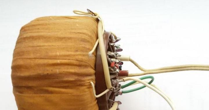
1. The basis of the power supply and its output characteristics are determined by the current source - the transformer used. In my case, a toroidal transformer from a washing machine was used. The transformer has two output windings for 8V and 15V. By connecting both windings in series and adding a rectifier bridge using medium-power diodes KD202M available at hand, I obtained a constant voltage source of 23V, 2A for the power supply.

Photo 3. Transformer and rectifier bridge.
2. Another defining part of the power supply is the device body. In this case, a children's slide projector hanging around in the garage found use. By removing the excess and processing the holes in the front part for installing an indicating microammeter, a blank power supply housing was obtained.

Photo 4. PSU body blank
3. The electronic circuit is mounted on a universal mounting plate measuring 45 x 65 mm. The layout of the parts on the board depends on the sizes of the components found on the farm. Instead of resistors R6 (setting the operating current) and R10 (limiting the maximum output voltage), trimming resistors with a value increased by 1.5 times are installed on the board. After setting up the power supply, they can be replaced with permanent ones.

Photo 5. Circuit board
4. Assembling the board and remote elements of the electronic circuit in full for testing, setting and adjusting the output parameters.

Photo 6. Power supply control unit
5. Fabrication and adjustment of a shunt and additional resistance for using a microammeter as an ammeter or power supply voltmeter. Additional resistance consists of permanent and trimming resistors connected in series (pictured above). The shunt (pictured below) is included in the main current circuit and consists of a wire with low resistance. The wire size is determined by the maximum output current. When measuring current, the device is connected in parallel to the shunt.

Photo 7. Microammeter, shunt and additional resistance
Adjustment of the length of the shunt and the value of additional resistance is carried out with the appropriate connection to the device with control for compliance using a multimeter. The device is switched to the Ammeter/Voltmeter mode using a toggle switch in accordance with the diagram:

Photo 8. Control mode switching diagram
6. Marking and processing of the front panel of the power supply unit, installation of remote parts. In this version, the front panel includes a microammeter (toggle switch for switching the A/V control mode to the right of the device), output terminals, voltage and current regulators, and operating mode indicators. To reduce losses and due to frequent use, a separate stabilized 5 V output is additionally provided. Why is the voltage from the 8V transformer winding supplied to the second rectifier bridge and a typical 7805 circuit with built-in protection.

Photo 9. Front panel
7. PSU assembly. All power supply elements are installed in the housing. In this embodiment, the radiator of the control transistor VT1 is an aluminum plate 5 mm thick, fixed in the upper part of the housing cover, which serves as an additional radiator. The transistor is fixed to the radiator through an electrically insulating gasket.
A protection design for any type of power supply is presented. This protection circuit can work together with any power supply - mains, switching and DC batteries. The schematic decoupling of such a protection unit is relatively simple and consists of several components.
Power supply protection circuit
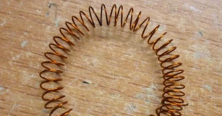
The power part - a powerful field-effect transistor - does not overheat during operation, therefore it does not need a heat sink either. The circuit is at the same time a protection against power overload, overload and short circuit at the output, the protection operation current can be selected by selecting the resistance of the shunt resistor, in my case the current is 8 Amperes, 6 resistors of 5 watts 0.1 Ohm connected in parallel were used. The shunt can also be made from resistors with a power of 1-3 watts.
The protection can be more accurately adjusted by selecting the resistance of the trimming resistor. Power supply protection circuit, current limit regulator Power supply protection circuit, current limit regulator
~~~In the event of a short circuit and overload of the unit output, the protection will instantly operate, turning off the power source. An LED indicator will indicate that the protection has been triggered. Even if the output short-circuits for a couple of tens of seconds, the field-effect transistor remains cold
~~~The field-effect transistor is not critical; any switches with a current of 15-20 Amps or higher and an operating voltage of 20-60 Volts will do. Keys from the IRFZ24, IRFZ40, IRFZ44, IRFZ46, IRFZ48 line or more powerful ones - IRF3205, IRL3705, IRL2505 and the like are ideal.
~~~This circuit is also great for protecting a charger for car batteries; if the connection polarity is suddenly reversed, then nothing bad will happen to the charger; the protection will save the device in such situations.
~~~Thanks to the fast operation of the protection, it can be successfully used for pulsed circuits; in the event of a short circuit, the protection will operate faster than the power switches of the switching power supply have time to burn out. The circuit is also suitable for pulse inverters, as current protection. If there is an overload or short circuit in the secondary circuit of the inverter, the inverter's power transistors instantly fly out, and such protection will prevent this from happening.
Comments
Short circuit protection, polarity reversal and overload are assembled on a separate board. The power transistor was used in the IRFZ44 series, but if desired, it can be replaced with a more powerful IRF3205 or with any other power switch that has similar parameters. You can use keys from the IRFZ24, IRFZ40, IRFZ46, IRFZ48 line and other keys with a current of more than 20 Amps. During operation, the field-effect transistor remains icy. therefore it does not need a heat sink.

The second transistor is also not critical; in my case, a high-voltage bipolar transistor of the MJE13003 series was used, but there is a large choice. The protection current is selected based on the shunt resistance - in my case, 6 0.1 Ohm resistors in parallel, the protection is triggered at a load of 6-7 Amps. You can set it more precisely by rotating the variable resistor, so I set the operating current to around 5 Amps.

The power of the power supply is quite decent, the output current reaches 6-7 Amps, which is quite enough to charge a car battery.
I chose shunt resistors with a power of 5 watts, but 2-3 watts is also possible.


If everything is done correctly, the unit starts working immediately, close the output, the protection LED should light up, which will light up as long as the output wires are in short-circuit mode.
If everything works as it should, then we proceed further. Assembling the indicator circuit.

The circuit is copied from a battery screwdriver charger. The red indicator indicates that there is output voltage at the power supply output, the green indicator shows the charging process. With this arrangement of components, the green indicator will gradually go out and finally go out when the voltage on the battery is 12.2-12.4 Volts; when the battery is disconnected, the indicator will not light up. 
I think every radio amateur who regularly designs electronic devices has an regulated power supply at home. The thing is really convenient and useful, without which, once you try it in action, it becomes difficult to do without. Indeed, if we need to check, for example, an LED, we will need to accurately set its operating voltage, since if the voltage supplied to the LED is significantly exceeded, the latter may simply burn out. Also with digital circuits, we set the output voltage on the multimeter to 5 volts, or any other voltage we need and go ahead.
Many novice radio amateurs first assemble a simple regulated power supply, without adjusting the output current and without short circuit protection. So it was with me, about 5 years ago I assembled a simple power supply with only adjustable output voltage from 0.6 to 11 volts. Its diagram is shown in the figure below:

But a few months ago I decided to upgrade this power supply and add a small short circuit protection circuit to its circuit. I found this diagram in one of the issues of Radio magazine. Upon closer examination, it turned out that the circuit is in many ways reminiscent of the above circuit diagram of the power supply I assembled earlier. If there is a short circuit in the powered circuit, the short circuit LED goes out, signaling this, and the output current becomes equal to 30 milliamps. It was decided to take part of this scheme and supplement it with my own, which is what I did. The original diagram from Radio magazine, which includes an addition, is shown in the figure below:

The following picture shows the part of this circuit that will need to be assembled.

The value of some parts, in particular resistors R1 and R2, needs to be recalculated upward. If anyone still has questions about where to connect the output wires from this circuit, I will provide the following figure:

I’ll also add that in the assembled circuit, regardless of whether it is the first circuit or the circuit from the Radio magazine, you must place a 1 kOhm resistor at the output, between plus and minus. In the diagram from Radio magazine this is resistor R6. All that remains is to etch the board and assemble everything together in the power supply case. Mirror boards in the program Sprint Layout no need. Short circuit protection circuit board drawing:

About a month ago I came across a diagram of an output current regulator attachment that could be used in conjunction with this power supply. I took it from this site. Then I assembled this set-top box in a separate case and decided to connect it as needed to charge batteries and similar actions where monitoring the output current is important. Here is the diagram of the set-top box, the transistor KT3107 in it was replaced with KT361.

But later the idea came to me to combine, for convenience, all this in one building. I opened the power supply case and looked, there was not enough space left, the variable resistor would not fit. The current regulator circuit uses a powerful variable resistor, which has rather large dimensions. Here's what it looks like:

Then I decided to simply connect both cases with screws, making the connection between the boards with wires. I also set the toggle switch to two positions: output with adjustable current and unregulated. In the first case, the output from the main board of the power supply was connected to the input of the current regulator, and the output of the current regulator went to the clamps on the power supply case, and in the second case, the clamps were connected directly to the output from the main board of the power supply. All this was switched with a six-pin toggle switch in 2 positions. Here is a drawing of the current regulator printed circuit board:

In the figure of the printed circuit board, R3.1 and R3.3 indicate the first and third terminals of the variable resistor, counting from the left. If anyone wants to repeat it, here is a diagram for connecting a toggle switch for switching:

Printed circuit boards of the power supply, protection circuits and current control circuits are attached in the archive. Material prepared by AKV.
Emergency “extra currents” and “extra voltages” do not benefit any electronic device. It is necessary to introduce protective circuits with automatic limitation, reduction, power off or, in extreme cases, with visual/audible indication of an emergency condition.
The simplest element of protection is a fuse. When choosing it, you need to focus on the standard rated operating currents:
SMD fuses - 62; 125; 250; 375; 500; 750 mA, 1.0; 1.5; 2.0; 2.5; 3.0; 3.5; 4.0; 5.0 A;
Conventional “glass” fuses - 50; 60; 80; 100; 160; 200; 250; 315; 500; 630; 800 mA, 1.0; 1.25; 1.6; 2.0; 3.15; 3.5; 4.0 A.

The tripping time of the fuse depends on the amount of current flowing. Judging by Table. 6.9, you cannot rely on the rated current of PLAV; it must be exceeded many times, for example, 4/PLAV. In practice, it is believed that a fuse-link labeled “1A” is guaranteed to “burn out” at a current of 2.5 A.
Radio amateurs, due to lack of time, sometimes make homemade wire fuses, colloquially called “bugs.” If copper wire is used, then you can take the data from Table. 6.10. Of course, after the experiment, the “bugs” must be replaced with normal fuses.
It is necessary to distinguish fuses from fusible resistors. The latter are similar in design to conventional resistors, but when they burn out they do not leave a black spot of metallized soot around them, which can short-circuit other circuits on the printed circuit board.
Another important protection element is varistors (Table 6.11). Unlike fuses, they are not installed in series, but in parallel, i.e. Protection is based on voltage, not current.
If the voltage is less than the threshold, then the resistance of the varistor is high, and it has virtually no effect on the protected circuit. If the threshold is reached, the resistance of the varistor quickly decreases. This allows you to effectively protect equipment from short-term impulse noise.
In Fig. 6.20, a...k shows power protection circuits from voltage surges and short circuits.
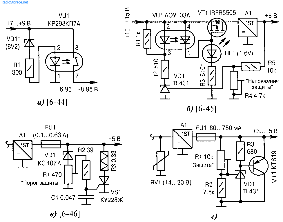
Rice. 6.20. Power surge and short circuit protection circuits (start):
a) protection against increased input voltage with a threshold determined by the zener diode VD1. Optorelay VU1 has normally closed contacts with a load current of no more than 250 mA;
b) electronic power off in the event of breakdown of a powerful control transistor located inside the voltage stabilizer A1. The performance is determined by the parameters of the optothyristor VU1. The HL1 emitter indicates an emergency condition in red. Resistor R3 sets the transition voltage of transistor VT1 to the closed state;
c) “parallel” protection of the +5 V circuit. During voltage surges, thyristor VS1 opens and fuse link FU1 (or self-resetting fuse) burns out. Capacitor C1 eliminates false triggering of the thyristor. A powerful wirewound resistor R3 protects the thyristor VS1 from “extra currents”. The threshold voltage of the VDI zener diode has a spread of 3.1...3.5 V, so its exact value is set by adjusting resistor R1.
d) similar to Fig. 6.20, in, but with the replacement of the thyristor switch with a powerful parallel voltage stabilizer on the elements VDI, VTI, R1...R3 and additional input protection using the varistor RV1. The response threshold is set by resistor R1 at a level approximately 0.2...0.4 V higher than the supply voltage +3...+5 V;

Rice. 6.20. Power protection circuits against voltage surges and short circuits (end):
e) HL1 is an indicator of a decrease in supply voltage from +5 to +4 V, which may indicate a pre-emergency condition. The exact threshold is set by resistor R3. The diagram serves only to indicate problems. Troubleshooting is done manually by the operator;
f) protection against interference and overvoltage in the vehicle’s on-board network (elements R1, C1). The flashing LED HL1 serves as an indicator of incorrect power supply polarity;
g) the red color of the HL1 LED indicates a break in the FU1 fuse, green - normal operation. If the color is orange or yellow, you should choose a different type of diode VD1
h) protection against overcurrent in the negative wire. Resistor R3 achieves trigger mode of operation. Resistor R1 sets the protection current within the range of 10...600 mA. For reference, if R2 = 10 Ohm, then the response current is 85... 111 mA;
i) varistor protection of devices connected to the telephone line. If the amplitude is large or the 220 V mains voltage is accidentally supplied, the fuse-link FU1 burns out;
j) Zener diode VD2 protects against input voltage surges. The current is limited by resistor R1, short pulse noise is smoothed out by capacitor C1.
The integrated circuit (IC) KR142EN12A is an adjustable voltage stabilizer of the compensation type in the KT-28-2 package, which allows you to power devices with a current of up to 1.5 A in the voltage range of 1.2...37 V. This integrated stabilizer has thermally stable protection according to current and output short circuit protection.
Based on the KR142EN12A IC, you can build an adjustable power supply, the circuit of which (without a transformer and diode bridge) is shown in Fig.2. The rectified input voltage is supplied from the diode bridge to capacitor C1. Transistor VT2 and chip DA1 should be located on the radiator.
Heat sink flange DA1 is electrically connected to pin 2, so if DAT and transistor VD2 are located on the same heatsink, then they need to be isolated from each other.
In the author's version, DA1 is installed on a separate small radiator, which is not galvanically connected to the radiator and transistor VT2. The power dissipated by a chip with a heat sink should not exceed 10 W. Resistors R3 and R5 form a voltage divider included in the measuring element of the stabilizer. A stabilized negative voltage of -5 V is supplied to capacitor C2 and resistor R2 (used to select the thermally stable point VD1). In the original version, the voltage is supplied from the KTs407A diode bridge and the 79L05 stabilizer, powered from a separate winding of the power transformer.
For guard from closing the output circuit of the stabilizer, it is enough to connect an electrolytic capacitor with a capacity of at least 10 μF in parallel with resistor R3, and shunt resistor R5 with a KD521A diode. The location of the parts is not critical, but for good temperature stability it is necessary to use the appropriate types of resistors. They should be located as far as possible from heat sources. The overall stability of the output voltage consists of many factors and usually does not exceed 0.25% after warming up.
After switching on and warming up the device, the minimum output voltage of 0 V is set with resistor Rao6. Resistors R2 ( Fig.2) and resistor Rno6 ( Fig.3) must be multi-turn trimmers from the SP5 series.
Possibilities the current of the KR142EN12A microcircuit is limited to 1.5 A. Currently, there are microcircuits on sale with similar parameters, but designed for a higher current in the load, for example LM350 - for a current of 3 A, LM338 - for a current of 5 A. Recently on sale imported microcircuits from the LOW DROP series (SD, DV, LT1083/1084/1085) appeared. These microcircuits can operate at a reduced voltage between input and output (up to 1... 1.3 V) and provide a stabilized output voltage in the range of 1.25...30 V at a load current of 7.5/5/3 A, respectively . The closest domestic analogue in terms of parameters, type KR142EN22, has a maximum stabilization current of 7.5 A. At the maximum output current, the stabilization mode is guaranteed by the manufacturer at an input-output voltage of at least 1.5 V. The microcircuits also have built-in protection against excess current in the load of the permissible value and thermal protection against overheating of the case. These stabilizers provide output voltage instability of 0.05%/V, output voltage instability when the output current changes from 10 mA to a maximum value of no worse than 0.1%/V. On Fig.4 shows a power supply circuit for a home laboratory, which allows you to do without transistors VT1 and VT2, shown in Fig.2.

Instead of the DA1 KR142EN12A microcircuit, the KR142EN22A microcircuit was used. This is an adjustable stabilizer with a low voltage drop, which allows you to obtain a current of up to 7.5 A in the load. For example, the input voltage supplied to the microcircuit is Uin = 39 V, output voltage at the load Uout = 30 V, current at the load louf = 5 A, then the maximum power dissipated by the microcircuit at the load is 45 W. Electrolytic capacitor C7 is used to reduce output impedance at high frequencies, and also reduces noise voltage and improves ripple smoothing. If this capacitor is tantalum, then its nominal capacity must be at least 22 μF, if aluminum - at least 150 μF. If necessary, the capacitance of capacitor C7 can be increased. If the electrolytic capacitor C7 is located at a distance of more than 155 mm and is connected to the power supply with a wire with a cross-section of less than 1 mm, then an additional electrolytic capacitor with a capacity of at least 10 μF is installed on the board parallel to the capacitor C7, closer to the microcircuit itself. The capacitance of filter capacitor C1 can be determined approximately at the rate of 2000 μF per 1 A of output current (at a voltage of at least 50 V).  To reduce the temperature drift of the output voltage, resistor R8 must be either wire-wound or metal-foil with an error of no worse than 1%. Resistor R7 is the same type as R8. If the KS113A zener diode is not available, you can use the unit shown in Fig.3. The author is quite satisfied with the protection circuit solution given in, as it works flawlessly and has been tested in practice. You can use any power supply protection circuit solutions, for example those proposed in. In the author’s version, when relay K1 is triggered, contacts K 1.1 are closed, short-circuiting resistor R7, and the voltage at the output of the power supply becomes equal to 0 V. The printed circuit board of the power supply and the location of the elements are shown in Fig. 5, the appearance of the power supply is shown in Fig.6.