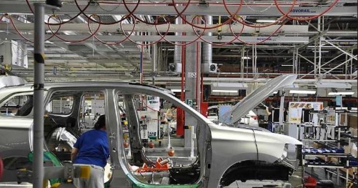
The IDEA to use gas turbine engines in automobiles has arisen long ago. But only in the last few years has their design reached the level of perfection that gives them the right to exist.
The high level of development of the theory of blade motors, metallurgy and production technology now provides a real possibility of creating reliable gas turbine engines capable of successfully replacing piston engines on a car internal combustion.
What is a gas turbine engine?
In fig. shown circuit diagram such an engine. A rotary compressor, located on the same shaft as the gas turbine, draws in air from the atmosphere, compresses it and pumps it into the combustion chamber. The fuel pump, also driven by the turbine shaft, pumps fuel into an injector located in the combustion chamber. The gaseous products of combustion enter through the guide vane onto the rotor blades of the gas turbine wheel and force it to rotate in one definite direction. The exhaust gases in the turbine are released into the atmosphere through a branch pipe. The gas turbine shaft rotates in bearings.
Compared with internal combustion piston engines, the gas turbine engine has very significant advantages. True, he, too, is not yet free of shortcomings, but they are gradually eliminated as the design develops.
When characterizing a gas turbine, first of all, it should be noted that, like a steam turbine, it can develop high speeds. This makes it possible to obtain significant power from much smaller (compared to piston) and almost 10 times lighter in weight engines.
The rotary motion of the shaft is essentially the only kind of motion in a gas turbine, while in an internal combustion engine, in addition to rotational motion crankshaft, there is a reciprocating movement of the piston, as well as a complex movement of the connecting rod. Gas turbine engines do not require special cooling devices. The absence of rubbing parts with a minimum number of bearings ensures long-term performance and high reliability of the gas turbine engine.
To power the gas turbine engine, kerosene or diesel fuel is used.
The main reason that hinders the development of automobile gas turbine engines is the need to artificially limit the temperature of the gases entering the turbine blades. This reduces the efficiency of the engine and leads to an increased specific fuel consumption (by 1 hp). The gas temperature has to be limited for gas turbine engines of passenger and trucks within 600-700 ° С, and in aircraft turbines up to 800-900 ° С because high heat-resistant alloys are still very expensive.
Currently, there are already some ways to increase the efficiency of gas turbine engines by cooling the blades, using the heat of exhaust gases to heat the air entering the combustion chambers, producing gases in highly efficient free-piston generators operating on a diesel-compressor cycle with a high compression ratio and etc. The solution to the problem of creating a highly efficient automobile gas turbine engine largely depends on the success of work in this area.

Schematic diagram of a two-shaft gas turbine engine with a heat exchanger
Most of the existing automobile gas turbine engines are built according to the so-called two-shaft scheme with heat exchangers. Here, a special turbine 8 is used to drive the compressor 1, and a traction turbine 7 is used to drive the wheels of the car. The shafts of the turbines are not interconnected. Gases from the combustion chamber 2 are first supplied to the turbine blades of the compressor drive, and then to the blades of the traction turbine. The air forced by the compressor, before entering the combustion chambers, is heated in heat exchangers 3 due to the heat given off by the exhaust gases. The use of a two-shaft scheme creates an advantageous traction characteristic gas turbine engines, which makes it possible to reduce the number of stages in a conventional vehicle gearbox and improve its dynamic properties.

Due to the fact that the traction turbine shaft is not mechanically connected to the compressor turbine shaft, its speed can vary depending on the load without significantly affecting the compressor shaft speed. As a consequence, the characteristic of the torque of the gas turbine engine has the form shown in Fig., Where the characteristic of the piston is also plotted for comparison. car engine(dotted line).
It can be seen from the diagram that in a piston engine, as the number of revolutions decreases, which occurs under the influence of an increasing load, the torque initially increases slightly and then decreases. At the same time, in a twin-shaft gas turbine engine, the torque automatically increases as the load increases. As a result, the need to change the gearbox is eliminated or occurs much later than with a piston engine. On the other hand, acceleration during acceleration in a two-shaft gas turbine engine will be much greater.
The characteristic of a single-shaft gas turbine engine differs from that shown in Fig. and, as a rule, inferior, in terms of the requirements of the dynamics of the car, the characteristics of the piston engine (at equal power).

The gas turbine engine has great prospects. In this engine, gas for the turbine is produced in a so-called free piston generator, which is a two-stroke diesel engine and a piston compressor combined in a common unit. The energy from the diesel pistons is transferred directly to the compressor pistons. Due to the fact that the movement piston groups is carried out exclusively under the influence of gas pressure and the mode of movement depends only on the course of thermodynamic processes in diesel and compressor cylinders, such a unit is called a free-piston unit. In its middle part there is a cylinder 4, open on both sides, having a direct-flow slot blowing, in which a two-stroke working process with compression ignition takes place. In the cylinder, two pistons move oppositely, one of which 9 opens during the working stroke and closes the exhaust ports cut in the cylinder walls during the return stroke. Another piston 3 also opens and closes the purge ports. The pistons are connected to each other by a light rack or pinion synchronizing mechanism, not shown in the diagram. When they get closer, the air trapped between them is compressed; by the time the dead point is reached, the temperature of the compressed air becomes sufficient to ignite the fuel, which is injected through the nozzle 5. As a result of the combustion of the fuel, gases with high temperature and pressure are formed; they force the pistons to spread apart, while the piston 9 opens the exhaust ports through which the gases rush into the gas collector 7. Then the purge ports open through which compressed air enters the cylinder 4, displaces the exhaust gases from the cylinder, mixes with them and also enters the gas collector. While the purge ports remain open, compressed air has time to clear the cylinder from exhaust gases and fill it, thus preparing the engine for the next working stroke.
Compressor pistons 2 are connected to pistons 3 and 9 and move in their cylinders. With the diverging stroke of the pistons, air is sucked from the atmosphere into the compressor cylinders, while the self-acting inlet valves 10 are open, and the outlet valves 11 are closed. With the opposite stroke of the pistons, the intake valves are closed, and the exhaust valves are open, and through them air is pumped into the receiver 6, which surrounds the diesel cylinder. The pistons move towards each other due to the air energy accumulated in the buffer cavities 1 during the previous working stroke. Gases from the collector 7 enter the traction turbine 8, the shaft of which is connected to the transmission. The following comparison of efficiency factors shows that the described gas turbine engine is already as efficient as internal combustion engines in terms of its efficiency:
Diesel 0.26-0.35
Gasoline engine 0.22-0.26
Gas turbine with constant volume combustion chambers without heat exchanger 0.12-0.18
Gas turbine with constant volume combustion chambers with heat exchanger 0.15-0.25
Gas turbine with free piston gas generator 0.25-0.35
Thus, the efficiency of the best samples of turbines is not inferior to the efficiency of diesel engines. It is no coincidence that the number of experimental gas turbine vehicles of various types is increasing every year. All new firms in various countries are announcing their work in this area.

This two-chamber engine, without heat exchanger, has an effective output of 370 hp. with. It is powered by kerosene. The compressor shaft rotation speed reaches 26,000 rpm, and the traction turbine shaft rotation speed ranges from 0 to 13,000 rpm. The temperature of the gases entering the turbine blades is 815 ° C, the air pressure at the compressor outlet is 3.5 atm. Total weight power plant designed for a racing car is 351 kg, with the gas-producing part weighing 154 kg, and the traction part with a gearbox and transmission to the drive wheels - 197 kg.
Gas turbine engine - is a thermal power unit, which carries out its work on the principle of reorganization of thermal energy into mechanical energy.
Below we will take a closer look at how a gas turbine engine works, as well as its structure, varieties, advantages and disadvantages.

Distinctive features of gas turbine engines
Today, this type of engine is most widely used in aviation. Alas, due to the peculiarities of the device, they cannot be used for ordinary cars.
Compared to other internal combustion units, the gas turbine engine has the highest power density, which is its main advantage. In addition, such an engine is capable of operating not only on gasoline, but also on many other types of liquid fuel. As a rule, it runs on kerosene or diesel fuel.
Gas turbine and piston engine, which are installed on "cars" by burning fuel, change the chemical energy of the fuel into heat, and then into mechanical.
But the process itself for these units is slightly different. In both engines, first, the intake is carried out (that is, the air flow enters the engine), then the fuel is compressed and injected, after which the fuel assembly ignites, as a result of which it expands greatly and as a result is emitted into the atmosphere.
The difference is that in gas turbine devices all this takes place at the same time, but in different parts of the unit. In the piston, everything is carried out at one point, but in sequence.
Passing through the turbine motor, the air is strongly compressed in volume and, due to this, increases the pressure almost forty times.

The only movement in the turbine is rotational, when, like in other internal combustion units, in addition to the rotation of the crankshaft, the piston also moves.
The efficiency and power of a gas turbine engine is higher than that of a piston engine, despite the fact that the weight and dimensions are less.
For economical fuel consumption, the gas turbine is equipped with a heat exchanger - a ceramic disc that is powered by a low-speed engine.
The device and the principle of operation of the unit
By its design, the engine is not very complicated; it is represented by a combustion chamber, where nozzles and spark plugs are equipped, which are necessary for supplying fuel and producing a spark charge. The compressor is equipped on a shaft with a wheel with special blades.
In addition, the motor consists of such components as a gearbox, an inlet channel, a heat exchanger, a needle, a diffuser and an exhaust pipe.
As the compressor shaft rotates, the air flow entering through the inlet channel is captured by its blades. After increasing the compressor speed to five hundred meters per second, it is pumped into the diffuser. The air velocity at the outlet of the diffuser decreases, but the pressure increases. Then the air flow enters the heat exchanger, where it is heated by the exhaust gases, and then the air is fed into the combustion chamber.
Together with it, fuel gets there, which is sprayed through the nozzles. After the fuel is mixed with air, a fuel-air mixture is created, which ignites thanks to the spark received from the spark plug. At the same time, the pressure in the chamber begins to increase, and the turbine wheel is driven by gases falling on the wheel blades.

As a result, the wheel torque is transferred to the car's transmission, and the exhaust gases are released into the atmosphere.
Pros and cons of the engine
A gas turbine, like a steam turbine, develops high revs, which allows it to gain good power, despite its compact size.
The turbine is cooled very simply and efficiently, for this you do not need any additional devices. It has no rubbing elements, and there are very few bearings, due to which the engine is able to function reliably and for a long time without breakdowns.
The main disadvantage of such units is that the cost of the materials from which they are made is quite high. The price for the repair of gas turbine engines is also considerable. But, despite this, they are constantly being improved and developed in many countries of the world, including ours.
The gas turbine is not installed on cars, primarily due to the constant need to limit the temperature of the gases that enter the turbine blades. As a result, the efficiency of the apparatus decreases and fuel consumption increases.
Today, some methods have already been invented that make it possible to increase the efficiency of turbine engines, for example, by cooling the blades or using the heat of the exhaust gases to heat the air flow that enters the chamber. Therefore, it is quite possible that after a while, developers will be able to create an economical engine for a car with their own hands.
Among the main advantages of the unit are:
- Low content of harmful substances in exhaust gases;
- Ease of maintenance (no need to change the oil, and all parts are wear-resistant and durable);
- No vibrations, since it is possible to easily balance the rotating elements;
- Low noise level during operation;
- Good torque curve performance;
- Start up quickly and without difficulty, and the engine response to gas is not delayed;
- Increased power density.
Types of gas turbine engines
According to their structure, these units are divided into four types. The first of these is a turbojet, most of which are installed on military aircraft with high speed. The principle of operation is that gases escaping from the engine at high speed push the aircraft forward through the nozzle.
Another type is turboprop. Its device differs from the first one in that it has one more turbine section. This turbine is made up of a series of blades that take the remainder of the energy from the gases that have passed through the compressor turbine and thereby rotate the propeller.
The screw can be located both at the rear of the unit and at the front. Waste gases are discharged through exhaust pipes... Such a jet is equipped on airplanes flying at low speed and at low altitude.

The third type is a turbofan, which is similar in design to the previous engine, but its 2nd turbine section does not completely take energy from the gases, and therefore such engines also have exhaust pipes.
The main feature of such an engine is that its fan, closed in a casing, is powered by a turbine. low pressure... Therefore, the engine is also called 2-circuit, since the air flow passes through the unit, which is an internal circuit and through its external circuit, which is necessary only to direct the air flow, which pushes the motor forward.
The latest aircraft are equipped with turbofan engines. They function efficiently at high altitudes and are also economical.
The last type is turboshaft. The scheme and structure of a gas turbine engine of this type is almost the same as that of the previous engine, but almost everything is driven from its shaft, which is connected to the turbine. Most often it is installed in helicopters and even modern tanks.
Twin piston and small size engine
The most common engine is with two shafts, equipped with a heat exchanger. Compared to units with only 1 shaft, such units are more efficient and powerful. The 2-shaft engine is equipped with turbines, one of which is designed to drive the compressor and the other to drive the axles.

Such an assembly provides the machine with good dynamic characteristics and reduces the number of transmission speeds.
Small size gas turbine engines also exist. They consist of a compressor, a gas-air heat exchanger, a combustion chamber and two turbines, one of which is located in the same housing with a gas collector.
Small-sized gas turbine engines are used mainly on airplanes and helicopters that cover long distances, as well as on unmanned aerial vehicles and APUs.
Unit with free piston generator
Today devices of this type are the most promising for cars. The engine device is represented by a block that connects a piston compressor and a 2-stroke diesel engine. In the middle there is a cylinder with two pistons connected to each other using a special device.
The work of the engine begins with the fact that the air is compressed during the convergence of the pistons and the fuel is ignited. Gases are formed due to the burnt mixture, they contribute to the divergence of the pistons at elevated temperatures. Then the gases end up in the gas collector. Due to the purge slots, compressed air enters the cylinder, which helps to clean the unit from exhaust gases. Then the cycle starts over.
Ph.D. A.V. Ovsyannik, head. Department of Industrial Heat Power Engineering and Ecology;
Ph.D. A.V. Shapovalov, associate professor;
V.V. Bolotin, engineer;
Gomel State Technical University named after P.O. Sukhoi ", Republic of Belarus
The article provides a rationale for the possibility of creating a CHPP on the basis of a converted AGTD as part of a gas turbine unit (GTU), an assessment of the economic effect of the introduction of AGTD into the power industry as part of large and medium-sized CHPPs to repay peak electrical loads.
Aviation Gas Turbine Overview
One of the successful examples of the use of AGTD in the power industry is the cogeneration GTU 25/39, installed and in commercial operation at the Bezymyanskaya CHPP located in the Samara region in Russia, which is described below. The gas turbine unit is designed to generate electrical and thermal energy for the needs of industrial enterprises and household consumers. The electric power of the installation is 25 MW, and the heat capacity is 39 MW. The total capacity of the installation is 64 MW. The annual productivity of electricity is 161.574 GWh / year, heat energy is 244120 Gcal / year.
The unit is distinguished by the use of a unique aircraft engine NK-37, which provides an efficiency of 36.4%. This efficiency provides high plant efficiency unattainable in conventional thermal power plants, as well as a number of other advantages. The unit operates on natural gas with a pressure of 4.6 MPa and a flow rate of 1.45 kg / s. In addition to electricity, the unit produces 40 t / h of steam with a pressure of 14 kgf / cm 2 and heats up 100 t of heating water from 70 to 120 ° C, which makes it possible to provide light and heat to a small town.
When the installation is located on the territory of thermal power plants, no additional special units for chemical water treatment, water discharge, etc. are required.
Such gas turbine power plants are indispensable for use in cases where:
■ a comprehensive solution to the problem of supplying electric and thermal energy to a small town, industrial or residential area is required - the modularity of the installations makes it easy to assemble any option depending on the needs of the consumer;
■ industrial development of new areas of human life is being carried out, including those with living conditions, when the compactness and manufacturability of the installation is especially important. Normal operation of the unit is ensured in the ambient temperature range from -50 to +45 ° C under the influence of all other unfavorable factors: humidity up to 100%, precipitation in the form of rain, snow, etc .;
■ the efficiency of the installation is important: high efficiency ensures the possibility of producing cheaper electric and thermal energy and a short payback period (about 3.5 years) with capital investments in the construction of the installation of 10 million 650 thousand dollars. USA (according to the manufacturer).
In addition, the installation is distinguished by its environmental friendliness, the presence of multi-stage noise suppression, and full automation of control processes.
GTU 25/39 is a stationary unit of a block-container type with a size of 21 m by 27 m. Switchgear to reduce the output voltage to 220 or 380 V, a cooling tower for cooling water and a free-standing booster gas compressor. In the absence of the need for water and steam, the design of the installation is greatly simplified and cheaper.
The installation itself includes an NK-37 aircraft engine, a TKU-6 waste heat boiler and a turbine generator.
The total installation time of the unit is 14 months.
A large number of units based on converted AGTDs with a capacity from 1000 kW to several tens of MW are produced in Russia, they are in demand. This confirms the economic efficiency of their use and the need for further developments in this area of the industry.
Installations manufactured at CIS plants differ:
■ low specific capital investments;
■ block execution;
■ shortened installation time;
■ short payback period;
■ the possibility of full automation, etc.
Characteristics of a gas turbine unit based on a converted AI-20 engine
A very popular and most frequently used gas turbine unit based on the AI-20 engine. Consider a gas turbine CHPP (GTTPP), in relation to which studies were carried out and calculations of the main indicators were performed.
The GTTETs-7500 / 6.3 gas turbine combined heat and power plant with an installed electric power of 7500 kW consists of three gas turbine generators with AI-20 turboprop engines with a rated electric power of 2500 kW each.
Thermal power of the GTHPP is 15.7 MW (13.53 Gcal / h). Behind each gas turbine generator there is a gas heater for network water (GWGP) with finned pipes for heating water with exhaust gases for heating, ventilation and hot water supply of the settlement. The exhaust gases in the aircraft engine pass through each economizer in an amount of 18.16 kg / s with a temperature of 388.7 ° C at the inlet to the economizer. In the GPSV, the gases are cooled to a temperature of 116.6 о С and fed into the chimney.
For modes with reduced heat loads, bypassing the exhaust gas flow with outlet to the chimney is introduced. Water consumption through one economizer is 75 t / h. Mains water is heated from a temperature of 60 to 120 ° C and is supplied to consumers for heating, ventilation and hot water supply under a pressure of 2.5 MPa.
Technical indicators of a gas turbine unit based on the AI-20 engine: power - 2.5 MW; the degree of pressure increase - 7.2; the temperature of the gases in the turbine at the inlet - 750 О С, at the outlet - 388.69 О С; gas consumption - 18.21 kg / s; number of shafts - 1; air temperature in front of the compressor - 15 о С. Based on the available data, we calculate the output characteristics of the gas turbine unit according to the algorithm given in the source.
Output characteristics of a gas turbine unit based on the AI-20 engine:
■ specific useful work of the GTU (at η fur = 0.98): H e = 139.27 kJ / kg;
■ efficiency factor: φ = 3536;
■ air consumption at power N gtu = 2.5 MW: G k = 17.95 kg / s;
■ fuel consumption at power N gtu = 2.5 MW: G top = 0.21 kg / s;
■ total consumption of exhaust gases: g g = 18.16 kg / s;
■ specific air consumption in the turbine: g k = 0.00718 kg / kW;
■ specific heat consumption in the combustion chamber: q 1 = 551.07 kJ / kg;
■ effective efficiency of the gas turbine unit: η е = 0.2527;
■ specific consumption of equivalent fuel for generated electricity (with generator efficiency η gen = 0.95) without utilization of exhaust gas heat: b у. t = 511.81 g / kWh.
Based on the data obtained and in accordance with the calculation algorithm, you can proceed to obtaining technical and economic indicators. Additionally, we set the following: the installed electric power of the GTHPP - N set = 7500 kW, the nominal thermal power of the installed GTHPP GPPV - Qtp = 15736.23 kW, the electricity consumption for auxiliary needs is assumed to be 5.5%. As a result of the studies and calculations, the following values were determined:
■ gross primary energy coefficient of the GTHPP, equal to the ratio of the sum of the electric and thermal capacities of the GTHPP to the product of the specific fuel consumption with the lowest calorific value of the fuel, η b GTPP = 0.763;
■ net primary energy coefficient of GTTPP η n GTTPP = 0.732;
■ production efficiency electrical energy in the cogeneration gas turbine unit, equal to the ratio of the specific work of gas in the gas turbine unit to the difference in the specific heat consumption in the combustion chamber of the gas turbine unit per 1 kg of the working fluid and the specific heat removal in the gas turbine unit from 1 kg of the exhaust gases of the gas turbine unit, η e gtu = 0.5311.
Based on the available data, it is possible to determine the technical and economic indicators of the GTHPP:
■ consumption of equivalent fuel for power generation in a cogeneration gas turbine unit: VGt U = 231.6 g of fuel equivalent / kWh;
■ hourly consumption of equivalent fuel for power generation: B e gtu = 579 kg of fuel equivalent / h;
■ hourly consumption of equivalent fuel in a gas turbine unit: B h ey gtu == 1246 kg of reference fuel. t / h
Heat generation in accordance with the "physical method" refers to the remaining amount of equivalent fuel: B t h = 667 kg of fuel equivalent. t / h
The specific consumption of equivalent fuel for the production of 1 Gcal of heat in a cogeneration gas turbine unit will be: W t gtu = 147.89 kg of fuel equivalent / h.
Technical and economic indicators of mini-CHP are given in table. 1 (in the table and below, prices are given in Belarusian rubles, 1000 Belarusian rubles ~ 3.5 Russian rubles - Author's note).
Table 1. Technical and economic indicators of a mini-CHP based on the converted AGTD AI-20, sold at its own expense (prices are in Belarusian rubles).
| The name of indicators | Units
measurements |
The magnitude |
| Installed electrical power | MW | 3-2,5 |
| Installed thermal power | MW | 15,7 |
| Specific capital investments per unit of electrical power | RUB mln / kWh | 4 |
| Annual electricity supply | kWh | 42,525-10 6 |
| Annual heat supply | Gcal | 47357 |
| Unit cost: | ||
| - electricity | RUB / kWh | 371,9 |
| - thermal energy | RUB / G cal | 138700 |
| Balance sheet (gross) profit | RUB million | 19348 |
| Payback period | years | 6,3 |
| Break even | % | 34,94 |
| Profitability (overall) | % | 27,64 |
| Internal rate of return | % | 50,54 |
Economic calculations show that the payback period for investments in combined production of electricity and heat with AGTD is up to 7 years when projects are implemented at their own expense. At the same time, the construction period can be from several weeks for the installation of small installations with an electric power of up to 5 MW, up to 1.5 years when commissioning an installation with an electric power of 25 MW and a heat one of 39 MW. The shortened installation time is explained by the modular delivery of power plants based on AGTD with full factory readiness.
Thus, the main advantages of converted AGTDs, when introduced into the power industry, are as follows: low specific investment in such installations, short payback period, reduced construction time due to modularity of execution (the installation consists of assembly blocks), the possibility of complete automation of the station, etc.
For comparison, we will give examples of operating gas engine mini-CHPPs in the Republic of Belarus, their main technical and economic parameters are shown in table. 2.
Having made a comparison, it is easy to notice that, against the background of already operating installations, gas turbine installations based on converted aircraft engines have a number of advantages. Considering AGTP as highly maneuverable power plants, it is necessary to bear in mind the possibility of their significant overload by transferring them to a steam-gas mixture (due to the injection of water into the combustion chambers), while it is possible to achieve an almost threefold increase in the power of a gas turbine unit with a relatively small decrease in its efficiency.
The efficiency of these stations increases significantly when they are located at oil wells, using associated gas, at oil refineries, at agricultural enterprises, where they are as close as possible to consumers of thermal energy, which reduces energy losses during its transportation.
The use of the simplest stationary aviation gas turbines is promising to cover acute peak loads. In a conventional gas turbine, the time to take on the load after starting is 15-17 minutes.
Gas turbine stations with aircraft engines are very maneuverable, require a short (415 min) time to start from a cold state to full load, can be fully automated and controlled remotely, which ensures their effective use as an emergency reserve. The duration of the start-up until the full load of the operating gas turbine units is taken is 30-90 minutes.
The indicators of the maneuverability of the GTU based on the converted GTE AI-20 are presented in Table. 3.
Table 3. Indicators of maneuverability of GTU based on the converted GTE AI-20.
Conclusion
Based on the work carried out and the results of the study of gas turbine plants based on converted AGTDs, the following conclusions can be drawn:
1. An effective direction for the development of the thermal power industry in Belarus is the decentralization of energy supply using converted AGTDs, and the most effective is the combined generation of heat and electricity.
2. The AGTD unit can operate both autonomously and as part of large industrial enterprises and large thermal power plants, as a reserve for accepting peak loads, has a short payback period and shortened installation times. There is no doubt that this technology has the prospect of development in our country.
Literature
1. Khusainov R.R. Thermal power plant operation in the conditions of the wholesale electricity market // Energetik. - 2008. - No. 6. - S. 5-9.
2. Nazarov V.I. On the issue of calculating generalized indicators at CHPPs // Energetika. - 2007. - No. 6. - S. 65-68.
3. Uvarov V.V. Gas turbines and gas turbine installations - M .: Higher. school., 1970 .-- 320 p.
4. Samsonov V.S. Economics of enterprises in the energy complex - M .: Vyssh. shk., 2003 .-- 416 p.
Aircraft gas turbine, one of the main units of aviation gas turbine engines; compared to stationary gas turbines, Aircraft gas turbine at high power, it has small dimensions and weight, which is achieved by constructive perfection, high axial gas velocities in the flow path, high circumferential speeds of the impeller (up to 450 m / sec) and large (up to 250 kJ / kg or 60 to cal / kg) heat drop. Aircraft gas turbine allows you to get significant power: for example, a single-stage turbine ( rice. 1 ) modern engine develops power up to 55 Mw(75 thous. l. with.). Multistage Aircraft gas turbine (rice. 2 ), in which the power of one stage is usually 30-40 Mw(40-50 thous. l. with.). For Aircraft gas turbine high gas temperature (850-1200 ° C) at the turbine inlet is characteristic. At the same time, the required resource and reliable operation of the turbine are ensured by the use of special alloys with high mechanical properties at operating temperatures and creep resistance, as well as by cooling the nozzle and rotor blades, turbine housing and rotor discs.Distributed air cooling, in which the air taken from the compressor, passing through the channels of the cooling system, enters the flow path of the turbine.
Aircraft gas turbine serve to drive the compressor turbojet engine, compressor and fan of a two-circuit turbojet engine and for driving the compressor and propeller turboprop engine. Aircraft gas turbine also used to drive auxiliary units engines and aircraft - starting devices (starters), electric generators, fuel and oxidizer pumps in liquid propellant rocket engine.
Development Aircraft gas turbine follows the path of aerodynamic design and technological improvement; improving the gas-dynamic characteristics of the flow path to ensure high efficiency in a wide range of operating modes typical for an aircraft engine; reducing the mass of the turbine (at a given power); further increase in the gas temperature at the turbine inlet; application of the latest high-heat-resistant materials, coatings and efficient cooling of turbine blades and discs. Development Aircraft gas turbine is also characterized by a further increase in the number of steps: in modern Aircraft gas turbine the number of steps reaches eight.
Lit .: The theory of jet engines. Spatula machines, M., 1956; Skubachevsky G.S., Aviation gas turbine engines, M., 1965; Abiants V. X., The theory of gas turbines of jet engines, 2nd ed., M., 1965.
S. Z. Kopelev.