LIQUID ROCKET ENGINE (LRE), a jet engine that does not use the environment and runs on liquid rocket fuel. It can function in the atmosphere and in outer (interplanetary) space.
LRE - the main type of engines on spacecraft, is also widely used in high-altitude research and long-range combat ballistic missiles, anti-aircraft guided missiles; limitedly - in combat missiles of other classes, on experimental aircraft, etc.
According to their purpose, there are main (sustainer) rocket engines, booster blocks, upper stages, corrective, brake, steering, micro-rocket (they can operate in a pulsed mode). LRE fuel can be one-component and two-component (fuel and oxidizer); most modern rocket engines run on two-component fuel. The liquid-propellant engine consists of a combustion chamber (CS), a nozzle, a turbopump unit for fuel supply, a gas generator, an automation system, controls, an ignition system, telemetric sensors, auxiliary units (heat exchangers, steering drives, etc.), a frame, etc. Work is underway to create three-component rocket engines.
Fuel and oxidizer are injected under pressure into the combustion chamber through nozzles, mixed, evaporated and ignited. Ignition (ignition) of fuel can be carried out by chemical, pyrotechnic and electrical means. After ignition, the fuel burns at high pressures (in some cases up to 15-25 MPa and more). When fuel is burned, gaseous combustion products are formed ( working body), heated to a temperature of 3700-3900 K, which flow from the combustion chamber into the surrounding space through the nozzle. For the structural integrity of the combustion chamber at such a temperature, its continuous cooling is necessary. It can be carried out, for example, with the help of fuel flowing before entering the mixing head through the channels of the external cooling system of the combustion chamber. This cooling method is called regenerative. As the combustion products move along the length of the nozzle, their temperature and pressure decrease, and their speed increases, crossing the threshold of the speed of sound in the minimum (critical) section of the nozzle. At the exit from the nozzle, the outflow velocity reaches 2700-4500 m / s. The thrust created by each kilogram of gases escaping from the engine in 1 s is called the specific thrust impulse. The higher the flow rate, the greater the specific impulse and, therefore, the more perfect the fuel and engine. A distinction is made between liquid-propellant rocket engines with a turbo-pumping fuel supply without afterburning combustion products (open circuit), in which gas generation products, after being triggered in the turbine, are emitted into the environment through auxiliary nozzles (pressure in the combustion chambers 4.9-7.8 MPa), and liquid-propellant rocket engines with afterburning ( closed, or closed, circuit), in which the gas generation products, after being triggered in the turbine, are sent to the LPRE chamber for afterburning. Such liquid-propellant rocket engines do not have specific impulse losses due to the need to drive the turbopump unit, and the pressure level in the compressor station reaches 14.7-26.5 MPa.
Historical reference. Schematic diagram The LPRE was developed by K.E. Tsiolkovsky in 1903, who proved the possibility of using LPRE for space flights. The scientist also indicated the most profitable rocket fuels and investigated the issues of the structure of the main units. Practical work on the creation was started in 1921 in the USA by R. Goddard, who in 1926 carried out the world's first launch of a rocket with a liquid-propellant engine. In the late 1920s - early 1930s, the development of liquid-propellant engines began in the USSR, Germany and other countries. In 1931, the first Russian LPREs were tested - ORM (experimental rocket motor) and ORM-1, created by V.P. Glushko at the Leningrad Gas Dynamic Laboratory (GDL). In 1933, the OR-2 propulsion system designed by F.A. Zander, and engine-10, created by the Moscow Group for the Study of Jet Propulsion (GIRD), ensured the flight of a liquid-propellant rocket.
Before the start of World War II, prototypes of liquid-propellant rocket engines with a thrust of up to several hundred kg, intended for experimental aircraft, appeared in the USSR and the USA. In Germany, during World War II, in the process of intensive work in the field of rocket technology, various types of liquid-propellant rocket engines for military purposes were created, many of which were mass-produced. The best were the Wasserfall liquid-propellant rocket engine and V-2 ballistic missiles. The first serial Russian rocket engines were the RD-1 and RD-1KhZ engines, created by the end of the war in the GDL-OKB.
The further development of liquid-propellant rocket engines was determined by programs launched in the mid-1950s in the USSR and the USA to create intercontinental ballistic missiles and launch vehicles (PH). For their implementation, powerful, economical and compact rocket engines operating on oxygen-kerosene fuel were created. In the 1960s, liquid-propellant rocket engines operating on high-boiling fuels and oxygen-hydrogen rocket engines were created. The idea of a closed circuit was first developed in the late 1950s in the USSR at NII-1 (now the MV Keldysh Research Center) and implemented in 1960. Since the mid-1960s, these liquid-propellant engines have been widely used at PH (for example, “ Proton ", H-1). Along with powerful sustainer rocket engines, multi-member rocket engines of medium and low thrust have been created.
In the 1970s and 90s, one of the world's most powerful four-chamber liquid-propellant rocket engines, the RD-170 (pressure in the combustion chamber 24.5 MPa, thrust on the ground / in vacuum 7200/7900 kN), was created for the first stages of the Energiya rocket and space complex. - Buran "and its modifications RD-171 for PH" Zenith ", as well as high-resource main engine RD-0120 with thrust of 1961 kN for the 2nd stage PH" Energia "on energy-consuming fuel components (oxygen - kerosene); on strategic missile R-36M ("Satan") is equipped with an RD-264 engine with a thrust of 4520 kN with a pressure in the combustion chamber of 20.6 MPa. For the orbital spacecraft "Buran", for the first time in world practice, a cryogenic oxidizer - liquid oxygen and fuel - synthetic hydrocarbon synthne - was used for the spacecraft, which significantly increased the energy capabilities of the orbital vehicle and made its operation safer and more environmentally friendly. In 2001, the first firing test of the RD-191 oxygen-kerosene engine (closed circuit), created for the 1st stage of the Russian PH "Angara" family, was successfully carried out; in 2005 a four-chamber rocket engine RD-0124 (closed circuit) was developed for installation on the 3rd stage of the Soyuz-2-1 B PH. The largest foreign organizations involved in the development of liquid-propellant rocket engines are located in the United States. The leading company is Rocketdyne, which developed: in 2000 the RS-68 oxygen-hydrogen engine (open circuit, thrust 3230 kN) for installation on the Delta 4 rocket, in 2002 - the RS-83 oxygen-hydrogen rocket engine (closed circuit) with a thrust of 2900 kN as part of NASA's Space Launch Initiative (SLI).
Most of the Russian space rocket engines, which ensured the flights of the first Russian artificial satellites of the Earth, artificial satellites of the Sun, Moon, Mars, automatic stations to the Moon, Venus and Mars, spaceships, all geophysical and other rockets in 1949 - 70, were created under the leadership of V. P. Glushko, A. M. Isaev, S. A. Kosberg, M. V. Melnikov and other designers. Liquid rocket engines were widely developed in the USA, Great Britain, France and other countries.
Further development of liquid-propellant rocket engines is associated with the search and development of new fuels and the development of new technical principles providing a further increase in efficiency and a decrease in the dimensions and weight of the rocket engine. Work is underway to create propulsion systems for reusable launch vehicles based on liquid-propellant rocket engines and air-jet engines.
Lit .: Fundamentals of the theory and calculation of liquid rocket engines/ Edited by V.M. Kudryavtsev. 4th ed. M., 1993; Dobrovolsky M.V.Liquid rocket engines: design principles. 2nd ed. M., 2005.
Design solid fuel engine(TTRD) is simple; it consists of a body (combustion chamber) and a jet nozzle. The combustion chamber is the main supporting element of the engine and the rocket as a whole. The material for its manufacture is steel or plastic. Nozzle designed to accelerate gases to a certain speed and impart the required direction to the flow. It is a closed channel of a special profile. The housing contains fuel. The motor housing is usually made of steel, sometimes fiberglass. The part of the nozzle that experiences the greatest stress is made of graphite, refractory metals and their alloys, the rest is made of steel, plastics, graphite.
When the gas from the combustion of the fuel passes through the nozzle, it is expelled at a speed that can be greater than the speed of sound. As a result, the recoil force appears, the direction of which is opposite to the outflow of the gas jet. This power is called reactive, or just cravings. The housing and nozzle of operating engines must be protected from burning out; for this they use heat-insulating and heat-resistant materials.
Compared to other types of rocket engines, the TTRD is quite simple in structure, but it has a reduced thrust, short operating time and difficulty in control. Therefore, being quite reliable, it is mainly used to create thrust in "auxiliary" operations and in the engines of intercontinental ballistic missiles.
Until now, TTRDs have rarely been used on board spacecraft. One of the reasons for this is the excessive acceleration that is imparted to the structure and equipment of the rocket when the solid-propellant engine is running. And for the launch of the rocket, it is necessary that the engine develop a small thrust for an extended period of time.
Solid-propellant engines allowed the United States to launch its first artificial satellite in 1958, following the USSR, and to put the spacecraft on a flight path to other planets in 1959. To date, it is in the United States that the most powerful space turbojet engine, the DM-2, has been created, capable of developing a thrust of 1634 tons.
Prospects for the development of solid-propellant space engines are:
- improvement of engine manufacturing technologies;
- development of jet nozzles that can work longer;
- use of modern materials;
- improvement of blended fuel compositions, etc.
Solid propellant rocket engine (TTRD)- a solid fuel engine is most often used in rocket artillery and much less often in astronautics; is the oldest of the heat engines.
As a fuel in such engines, a solid substance (a mixture of individual substances) is used that can burn without oxygen, while releasing a large amount of hot gases that are used to create jet thrust.
There are two classes of rocket fuel: dual fuel and composite fuels.
Dibasic fuels- are solid solutions in a non-volatile solvent (most often nitrocellulose in nitroglycerin). Advantages - good mechanical, temperature and other structural characteristics, retain their properties during long-term storage, are simple and cheap to manufacture, environmentally friendly (there are no harmful substances during combustion). The disadvantage is the relatively low power and increased sensitivity to shocks. Charges from this fuel are most often used in small corrective engines.
Mixed fuels- modern mixtures consist of ammonium perchlorate (as an oxidizing agent), aluminum in the form of a powder and an organic polymer to bind the mixture. Aluminum and polymer play the role of fuel, with metal being the main source of energy and polymer being the main source of gaseous products. They are characterized by insensitivity to shocks, high combustion intensity at low pressures and it is very difficult to extinguish.
Fuel in the form of fuel charges is placed in the combustion chamber. After the start, combustion continues until the fuel is completely burned out, the thrust changes according to the laws due to fuel combustion, and is practically not regulated. The change in thrust is achieved by using fuels with different combustion rates and the choice of a suitable charge configuration.
With the help of an igniter, the fuel components are heated, a chemical oxidation-reduction reaction begins between them, and the fuel gradually burns out. This produces gas with high pressure and temperature. The pressure of the incandescent gases with the help of a nozzle turns into jet thrust, which in its magnitude is proportional to the mass of combustion products and the speed of their exit from the engine nozzle.
For all its simplicity, the exact calculation of the operational parameters of the turbojet engine is a difficult task.

Solid-propellant engines have a number of advantages over liquid-propellant rocket engines: the engine is simple enough to manufacture, can be stored for a long time, while maintaining its characteristics, and is relatively explosion-proof. However, in terms of power, they are inferior liquid engines by about 10-30%, have difficulties in power regulation and a large mass of the engine as a whole.
In some cases, a type of turbojet engine is used, in which one component of the fuel is in a solid state, and the second (most often an oxidizer) is in a liquid state.
1) Study of the scheme and principle of operation of a liquid-propellant rocket engine (LRE).
2) Determination of the change in the parameters of the working fluid along the path of the LPRE chamber.
- GENERAL INFORMATION ABOUT LRE
2.1. LPRE composition
The jet engine is called technical device, creating thrust as a result of the outflow of the working fluid from it. Jet engines provide acceleration of moving vehicles different types.
A rocket engine is a jet engine that uses only substances and energy sources available on board a moving vehicle to operate.
Liquid rocket engine (LRE) is a rocket engine that uses fuel (primary energy source and working fluid) in a liquid aggregate state for operation.
LRE generally consists of:
2- turbopump units (TNA);
3- gas generators;
4- pipelines;
5- automation units;
6- auxiliary devices
One or more liquid-propellant rocket engines, in conjunction with a pneumohydraulic system (PGS) for supplying fuel to the engine chambers and auxiliary units rocket stages, constitute a liquid-propellant rocket propulsion system (LRE).
A substance or several substances (oxidizer, fuel) that are capable of forming high-temperature combustion (decomposition) products as a result of exothermic chemical reactions are used as liquid rocket fuel (LRT). These products are the working fluid of the engine.
Each LRE chamber consists of a combustion chamber and a nozzle. In the LPRE chamber, the primary chemical energy of the liquid fuel is converted into the final kinetic energy of the gaseous working fluid, as a result of the expiration of which the reactive force of the chamber is created.
A separate turbo-pumping unit of a liquid-propellant engine consists of pumps and a turbine that drives them. TNA provides the supply of liquid fuel components to the chambers and gas generators of the liquid-propellant engine.
The LPRE gas generator is a unit in which the main or auxiliary fuel is converted into gas generation products used as a working fluid of the turbine and working bodies of the pressurization system of tanks with LPR components.
The liquid-propellant engine automation system is a set of devices (valves, regulators, sensors, etc.) of various types: electrical, mechanical, hydraulic, pneumatic, pyrotechnic, etc. Automation units provide starting, control, regulation and shutdown of the liquid-propellant engine.
LPRE parameters
The main thrust parameters of the rocket engine are:
The reactive force of the rocket engine - R - the resulting gas and hydrodynamic forces acting on the inner surfaces of the rocket engine when the substance outflows from it;
LRE thrust - R is the resultant of the reactive force of the liquid-propellant engine (R) and all environmental pressure forces that act on the outer surfaces of the engine, with the exception of the forces of external aerodynamic resistance;
LPRE thrust impulse - I - integral of LPRE thrust in terms of its operation time;
Specific impulse of rocket engine thrust - I y - ratio of thrust (P) to mass fuel consumption () rocket engine.
The main parameters that characterize the processes occurring in the rocket engine chamber are pressure (p), temperature (T) and flow rate (W) of combustion (decomposition) products of liquid rocket fuel. In this case, the values of the parameters at the nozzle inlet (section index "c"), as well as in the critical ("*") and outlet ("a") sections of the nozzle, are especially highlighted.
The calculation of the parameter values in different sections of the liquid-propellant engine nozzle path and the determination of the engine thrust parameters are carried out according to the corresponding thermogasodynamics equations. An approximate technique for such a calculation is discussed in section 4 of this manual.
- SCHEME AND PRINCIPLE OF OPERATION OF LRE "RD-214"
3.1. general characteristics Rocket engine "RD-214"
The RD-214 liquid-propellant rocket engine has been used in domestic practice since 1957. Since 1962, it has been installed on the first stage of the Kosmos multistage launch vehicles, with the help of which many satellites of the Kosmos and Interkomos series have been launched into near-earth orbits.
The RD-214 rocket engine has a fuel pumping system. The engine runs on a high-boiling nitric acid oxidizer (a solution of nitrogen oxides in nitric acid) and hydrocarbon fuel (kerosene processing products). A special component is used for the gas generator - liquid hydrogen peroxide.
The main parameters of the engine have the following meanings:
Thrust in the void P p = 726 kN;
Specific thrust impulse in the void I pack = 2590 N × s / kg;
Gas pressure in the combustion chamber p k = 4.4 MPa;
Gas expansion ratio in the nozzle e = 64
LPRE "RD-214", (Fig. 1) consists of:
Four chambers (pos. 6);
One turbopump unit (TNA) (pos. 1, 2, 3, 4);
Gas generator (item 5);
Pipeline;
Automation units (pos. 7, 8)
The engine TNA consists of an oxidizer pump (item 2), a fuel pump (item 3), a hydrogen peroxide pump (item 4) and a turbine (item 1). The rotor (rotating parts) of the pumps and the turbine are connected by a single shaft.
Units and assemblies providing the supply of components to the engine chamber, gas generator and turbine are combined into three separate systems - highways:
Oxidizer supply system
Fuel supply system
Hydrogen peroxide steam and gas generation system.
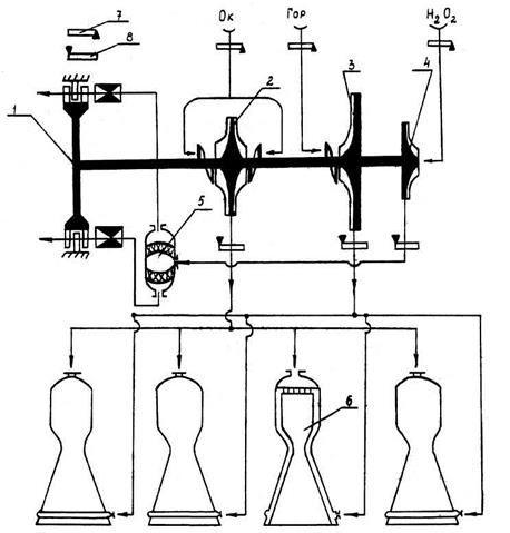
Fig. 1. Diagram of a liquid propellant rocket engine
1 - turbine; 2 - oxidizer pump; 3 - fuel pump;
4 - hydrogen peroxide pump; 5 - gas generator (reactor);
6 - engine chamber; 7, 8 - automation elements.
3.2. Characteristics of RD-214 rocket engine units
3.2.1. LRE chamber
Four rocket engine chambers are connected into a single block in two sections using bolts.
Each chamber of the liquid-propellant engine (pos. 6) consists of a mixing head and a housing. The mixing head includes upper, middle and lower (fire) bottoms. A cavity for the oxidizer is formed between the upper and middle bottoms, and a cavity for fuel is formed between the middle and fire bottoms. Each of the cavities is connected with the internal volume of the engine casing by means of corresponding nozzles.
In the process of operation of the liquid-propellant engine through the mixing head and its nozzles, the supply, atomization and mixing of liquid fuel components is carried out.
The liquid-propellant engine chamber housing includes a part of the combustion chamber and a nozzle. The liquid-propellant rocket engine nozzle is supersonic, has a converging and diverging parts.
The body of the liquid-propellant engine chamber is double-walled. The inner (fire) and outer (power) walls of the body are interconnected by spacers. In this case, with the help of spacers, channels of the liquid cooling path of the body are formed between the walls. Fuel is used as a coolant.
When the engine is running, fuel is supplied to the cooling path through special manifold pipes located at the end of the nozzle. Having passed the cooling path, the fuel enters the corresponding cavity of the mixing head and is introduced through the nozzles into the combustion chamber. At the same time, the oxidant enters the combustion chamber through another cavity of the mixing head and the corresponding nozzles.
In the volume of the combustion chamber, atomization, mixing and combustion of liquid fuel components takes place. The result is a high-temperature gaseous engine working fluid.
Then, in a supersonic nozzle, the thermal energy of the working fluid is converted into the kinetic energy of its jet, at the expiration of which the thrust of the liquid-propellant engine is created.
3.2.2. Gas generator and turbo pump unit
The gas generator (Fig. 1, item 5) is a unit in which liquid hydrogen peroxide, as a result of exothermic decomposition, is converted into a high-temperature vaporous working fluid of the turbine.
The turbopump unit provides a pressure supply of liquid fuel components to the chamber and gas generator of the engine.
TNA consists of (Fig. 1):
Oxidizer screw centrifugal pump (pos. 2);
Screw centrifugal fuel pump (pos. 3);
Hydrogen peroxide centrifugal pump (item 4);
Gas turbine(item 1).
Each pump and turbine has a fixed stator and a rotating rotor. Rotors of pumps and turbines have a common shaft, which consists of two parts, which are connected by a spring.
The turbine (item 1) drives the pumps. The main elements of the turbine stator are the housing and the nozzle apparatus, and the rotor is the shaft and the impeller with blades. During operation, peroxide steam is supplied to the turbine from the gas generator. When the steam gas passes through the nozzle apparatus and the turbine impeller blades, its thermal energy is converted into mechanical energy of rotation of the wheel and the turbine rotor shaft. The spent steam-gas is collected in the outlet manifold of the turbine housing and discharged into the atmosphere through special waste nozzles. This creates some additional thrust for the liquid-propellant engine.
The oxidizer (pos. 2) and fuel (pos. 3) pumps are of the screw centrifugal type. The main elements of each of the pumps are the casing and the rotor. The rotor has a shaft, auger and a centrifugal impeller with blades. During operation, mechanical energy is supplied from the turbine to the pump through the common shaft, which ensures the rotation of the pump rotor. As a result of the action of the auger blades and the centrifugal wheel on the fluid (fuel component) pumped by the pumps, the mechanical energy of the pump rotor rotation is converted into potential energy of the fluid pressure, which ensures the supply of the component to the engine chamber. The auger in front of the centrifugal impeller of the pump is installed to preliminary increase the fluid pressure at the inlet to the interscapular channels of the impeller in order to prevent cold boiling of the fluid (cavitation) and disruption of its continuity. Violations of the component flow continuity can cause instability of the fuel combustion process in the engine chamber, and, consequently, instability of the operation of the liquid-propellant engine as a whole.
A centrifugal pump (item 4) is used to supply hydrogen peroxide to the gas generator. The relatively low consumption of the component creates conditions for the cavitation-free operation of the centrifugal pump without installing a screw pre-pump in front of it.
3.3. How the engine works
Starting, controlling and stopping the engine is performed automatically by electrical commands from the rocket board to the corresponding automation elements.
For the initial ignition of the fuel components, a special starting fuel is used, self-igniting with an oxidizer. The starting fuel initially fills a small section of the pipeline in front of the fuel pump. At the moment of launching the liquid-propellant engine, starting fuel and an oxidizer enter the chamber, they self-ignite, and only then the main components of the fuel begin to be fed into the chamber.
In the process of engine operation, the oxidizer sequentially passes through the elements and assemblies of the line (system), including:
Separating valve;
Oxidizer pump;
Oxidizer valve;
Mixing head of the engine chamber.
The flow of fuel flows through a line including:
Dividing valves;
Fuel pump;
The manifold and the cooling path of the engine chamber;
Chamber mixing head.
Hydrogen peroxide and the resulting steam and gas sequentially pass through the elements and units of the steam and gas generation system, including:
Separating valve;
Hydrogen peroxide pump;
Hydraulic reducer;
Gas generator;
Turbine nozzle;
Turbine impeller blades;
Turbine manifold;
Waste nozzles.
As a result of the continuous supply of the fuel components by the turbo pump unit to the engine chamber, their combustion with the formation of a high-temperature working fluid and the outflow of the working fluid from the chamber, a thrust of the liquid-propellant engine is created.
Varying the thrust value of the engine during its operation is provided by changing the flow rate of hydrogen peroxide supplied to the gas generator. This changes the power of the turbine and pumps, and, consequently, the supply of fuel components to the engine chamber.
The liquid-propellant engine is shut down in two stages using automation elements. From the main mode, the engine is first transferred to the final mode of operation with less thrust and only then is completely switched off.
- WORK PROCEDURE
4.1. Scope and order of work
In the process of performing the work, the following actions are sequentially performed.
1) The scheme of the RD-214 rocket engine is being studied. The purpose and composition of the liquid-propellant engine, the design of the units, the principle of operation of the engine are considered.
2) Measurement is performed geometric parameters rocket engine nozzles. The diameter of the inlet ("c"), critical ("*") and outlet ("a") sections of the nozzle (D c, D *, D a) is found.
3) The value of the parameters of the working fluid of the liquid-propellant rocket engine in the inlet, critical and outlet sections of the nozzle of the liquid-propellant rocket engine is calculated.
Based on the results of the calculations, a generalized graph of changes in temperature (T), pressure (p) and velocity (W) of the working fluid along the nozzle path (L) of the liquid-propellant engine is constructed.
4) Determined traction parameters LRE at the design mode of the nozzle operation ().
4.2. Initial data for calculating the parameters of the RD-214 rocket engine
Gas pressure in the chamber (see option)
Temperature of gases in the chamber
Gas constant
Isoentrope exponent
Function ![]()
It is assumed that the processes in the chamber proceed without energy loss. In this case, the coefficients of energy loss in the combustion chamber and nozzle are respectively equal to ![]()
The operating mode of the nozzle is calculated (index " r»).
The measurement determines:
Nozzle throat diameter;
Diameter of the outlet section of the nozzle.
4.3. The sequence of calculating the parameters of the rocket engine
A) The parameters in the outlet section of the nozzle ("a") are determined in the following sequence.
1) Nozzle outlet area
2) Nozzle throat area
3) Geometric degree gas expansion

A liquid propellant rocket engine is an engine fueled by liquefied gases and chemical liquids. Depending on the number of components, liquid-propellant rocket engines are divided into one-, two- and three-component.
A brief history of development
For the first time, the use of liquefied hydrogen and oxygen as a fuel for rockets was proposed by K.E. Tsiolkovsky in 1903. The first LPRE prototype was created by the American Robert Howard in 1926. Subsequently, similar developments were carried out in the USSR, USA, Germany. The greatest successes were achieved by German scientists: Thiel, Walter, von Braun. During World War II, they created a whole line of liquid-propellant rocket engines for military purposes. It is believed that had created the Reich "V-2" earlier, they would have won the war. Subsequently, the Cold War and the arms race became a catalyst for accelerating the development of liquid-propellant rocket engines with the aim of using them in the space program. With the help of RD-108, the first artificial earth satellites were launched into orbit.
Today liquid-propellant rocket engines are used in space programs and heavy missile weapons.
Scope of application
As mentioned above, liquid-propellant rocket engines are used mainly as an engine for spacecraft and launch vehicles. The main advantages of liquid-propellant rocket engines are:
- the highest specific impulse in the class;
- the ability to perform a full stop and restart in tandem with traction control gives increased maneuverability;
- significantly less weight of the fuel compartment in comparison with solid fuel engines.
Among the disadvantages of rocket engines:
- more complex device and high cost;
- increased requirements for safe transportation;
- in a state of zero gravity, it is necessary to use additional engines to precipitate the fuel.
However, the main disadvantage of liquid-propellant rocket engines is the limit of the energy capabilities of the fuel, which limits space exploration with their help to the distance of Venus and Mars.
Device and principle of operation
The principle of operation of the rocket engine is the same, but it is achieved using different schemes of devices. The fuel and oxidizer are pumped from different tanks to the nozzle head, pumped into the combustion chamber and mixed. After ignition under pressure, the internal energy of the fuel is converted into kinetic energy and flows out through the nozzle, creating jet thrust.
The fuel system consists of fuel tanks, pipelines and pumps with a turbine for pumping fuel from the tank into the pipeline and a regulator valve.
Fuel pumping creates high pressure in the chamber and, as a consequence, a greater expansion of the working fluid, due to which the maximum value of the specific impulse is achieved.
Nozzle head - a block of nozzles for injecting fuel components into the combustion chamber. The main requirement for a nozzle is good mixing and speed of fuel supply to the combustion chamber.
Cooling system
Although the share of heat transfer from the structure in the combustion process is insignificant, the problem of cooling is urgent due to the high combustion temperature (> 3000 K) and threatens with thermal destruction of the engine. There are several types of cooling of the chamber walls:
Regenerative cooling is based on the creation of a cavity in the walls of the chamber, through which the fuel passes without an oxidizer, cooling the chamber wall, and the heat, together with the coolant (fuel), returns back to the chamber.
The wall layer is a layer of gas created from combustible vapors at the walls of the chamber. This effect is achieved by installing around the periphery of the nozzle head supplying only fuel. Thus, the combustible mixture lacks an oxidizing agent, and combustion at the wall is not as intense as in the center of the chamber. The near-wall temperature insulates the high temperatures in the center of the chamber from the walls of the combustion chamber.
The ablative method of cooling a liquid-propellant rocket engine is carried out by applying a special heat-shielding coating to the walls of the chamber and nozzles. At high temperatures, the coating changes from a solid to a gaseous state, absorbing a large proportion of the heat. This method of cooling a liquid propellant rocket engine was used in the Apollo lunar program.
Launching a liquid-propellant rocket engine is a very important operation in terms of explosion hazard in case of failures in its implementation. There are self-igniting components with which there is no difficulty, however, when using an external initiator for ignition, it is necessary to perfectly match its supply with the fuel components. The accumulation of unburned fuel in the chamber has a destructive explosive force and promises grave consequences.
Large liquid-propellant rocket engines are launched in several stages, followed by reaching maximum power, while small engines are launched with an immediate output of one hundred percent power.
System automatic control liquid-propellant rocket engines are characterized by safe engine start and exit to the main mode, stable operation control, thrust adjustment according to the flight plan, consumables adjustment, shutdown when entering a given trajectory. Due to the moments that cannot be calculated, the liquid-propellant engine is equipped with a guaranteed supply of fuel so that the rocket can enter a given orbit in case of deviations in the program.
Fuel components and their choice in the design process are decisive in the design of a liquid-propellant rocket engine. Based on this, the conditions of storage, transportation and production technology are determined. The most important indicator of the combination of components is the specific impulse, on which the distribution of the percentage of fuel and cargo mass depends. The dimensions and mass of the rocket are calculated using the Tsiolkovsky formula. In addition to the specific impulse, the density affects the size of tanks with fuel components, the boiling point can limit the operating conditions of missiles, chemical aggressiveness is inherent in all oxidizers and, if the rules for operating the tanks are not followed, it can cause a tank fire, the toxicity of some fuel compounds can cause serious harm to the atmosphere and the environment ... Therefore, although fluorine is a better oxidizing agent than oxygen, it is not used due to its toxicity.

Single-component liquid-propellant rocket engines use a liquid as fuel, which, interacting with a catalyst, decomposes with the release of hot gas. The main advantage of single-component rocket engines is their simplicity of design, and although the specific impulse of such engines is small, they are ideally suited as low-thrust engines for orientation and stabilization of spacecraft. These engines use a positive displacement fuel supply system and, due to the low process temperature, do not need a cooling system. Single-component engines also include gas jet engines, which are used in conditions of inadmissibility of thermal and chemical fumes.
In the early 70s, the United States and the USSR developed three-component liquid-propellant rocket engines that would use hydrogen and hydrocarbon fuel as fuel. Thus, the engine would run on kerosene and oxygen at start-up and switch to liquid hydrogen and oxygen at high altitude. An example of a three-component rocket engine in Russia is the RD-701.
Rocket control was first used in V-2 rockets using graphite gas-dynamic rudders, but this reduced engine thrust, and modern rockets use pivoting chambers attached to the body by hinges that create maneuverability in one or two planes. In addition to rotary cameras, control motors are also used, which are fixed with nozzles in the opposite direction and are turned on when it is necessary to control the apparatus in space.
A closed-cycle liquid-propellant engine is an engine, one of the components of which is gasified during combustion at low temperature with a small part of the other component, the resulting gas acts as a working fluid of the turbine, and then is fed into the combustion chamber, where it burns with the remnants of fuel components and creates jet thrust. The main disadvantage of this scheme is the complexity of the design, but the specific impulse increases.
The prospect of increasing the power of liquid propellant rocket engines
In the Russian school of liquid rocket engine creators, headed by Academician Glushko for a long time, they strive for the maximum use of fuel energy and, as a consequence, the maximum possible specific impulse. Since the maximum specific impulse can be obtained only with an increase in the expansion of combustion products in the nozzle, all developments are carried out in search of an ideal fuel mixture.