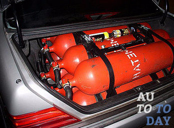
Recently, due to economically favorable conditions the installation has gained great popularity gas equipment on the car. Gas equipment (LPG) is a special device that allows you to store and supply gaseous fuel to the engine, due to which the car moves.
Brief description of gas equipment
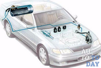
Methane and propane-butane mixture are used as gaseous fuel for gas equipment. Depending on what fuel is selected, as well as what type of engine is installed, gas-cylinder equipment is divided into single-fuel, gas-diesel and dual-fuel with independent supply of only one type of fuel to the engine. Each of these fuel systems has its own specific features, but with all this, it also has common features. The term “generation” is used in the classification of LPG systems. Today, as such, there is no official international classification regarding gas equipment of cars. We will consider the principle of operation of one of the latest systems - the fourth generation of gas equipment.
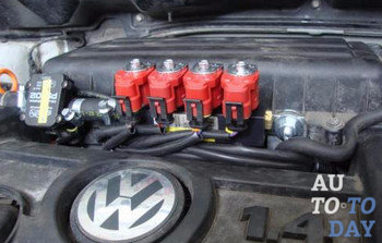
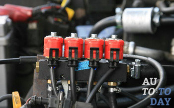
 In this case, the gas is injected either in parallel or sequentially and this is ensured by electromagnetic injectors... Their work is regulated by a special gas control unit, which reads the signals that go to the petrol injectors. And, guided by them, makes a calculation, and then gives the appropriate signals to the gas injectors. The gas that flows from the gearbox to the injectors is injected into the intake valves of the engine.
Disadvantages of LPG equipment:
- too expensive equipment;
The manufacturer's warranty expires upon installation;
Operational safety is enclosed in a rigid framework;
Difficulty finding gas stations;
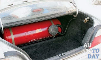
Luggage space is donated.
Advantages of LPG equipment:
- fuel economy;
The engine is operated in a softer mode;
Environmental friendliness.
Frequent malfunctions of gas equipment
In the first and second generations of gas equipment, the lack of supply of the gas mixture to the power plant is a consequence of the failure of the electromagnetic gas valve installed on. The high-speed valve sticks in the closed position. Clogged pipeline. The filter elements are clogged. The speed valve does not work. The flow valve does not open fully. The power plant of the car is muffled, gas continues to flow into the system for the reason that the switch is faulty, the reducer is out of order, the gas solenoid valve of the carburetor is depressurized.
 These difficulties associated with starting the car's power unit arise as a result of a gearbox malfunction. Gearbox incorrectly adjusted. The fuel mixture of gas and petrol is supplied simultaneously. The increased consumption of the gas mixture during freezing of the reducer occurs due to the depressurization of the reducer diaphragm. The cooling system is filled with air mass. The coolant level is too low.
The smell of gas is caused by a leak in the exhaust gases in the exhaust system. The carburetor solenoid valve is depressurized. Gas leaks from the gearbox housing and other gas line connections. While the power unit is idling, the engine speed may stop developing due to a malfunction of the gearbox itself, the ignition system, or the fact that the air filter is clogged.
Also fuel consumption the gas mixture may rise due to poor heating by the gearbox cooling fluid. Defective gearbox. Reduced compression level on the engine cylinders. Misalignment of the gearbox. Malfunctions in the ignition system. Air filter clogged. Let's look at the typical causes of malfunctions that relate to the third generation of LPG equipment. The car engine is not reaching full power due to software regulation malfunctions. Lambda probe, gas stepper regulator, reducer are faulty. Gas lines and gas filter clogged. An open throttle valve led to a failure due to the fact that the mixer was not selected correctly. The regulation of the entire system is broken. The sensor that fixes the position is faulty throttle.
 The engine, upon reaching the recommended temperature regime, does not switch to operation with a gas mixture due to the fact that there are no tachometer readings for the power unit revolutions. The gearbox temperature sensor is out of order. There were pops on the intake manifold when the throttle valve was opened. This is due to a violation of the heat regulation valve clearances gas distribution mechanism. Timing and ignition system defective. The intake tract is depressurized, as a result of which air is sucked in. Gas is supplied incorrectly by the stepper regulator or an incorrectly adjusted system depletes the fuel mixture.
Gas fuel consumption increases due to disturbed adjustments of the control lambda system. In this case, the problem lies in the malfunction of the lambda probe and the stepper regulator, which supplies the gas mixture. The compression level in the cylinders decreases power plant... There is a violation of the adjustments of the gearbox and the ignition system. And also due to the clogging of the air filter.
In the fourth generation of gas equipment, the following malfunctions are characteristic. Idling power unit ceases to work steadily. The reason for this is the disturbed adjustment of the thermal clearances on the valves of the gas distribution mechanism. The gas distribution mechanism has some kind of malfunction. Reduced engine compression level. The lambda probe is defective. The gas injection system is incorrectly adjusted. Malfunctions in the ignition system. Gas injectors are not provided with normal operating conditions. The engine is unable to reach full power due to a clogged fine filter, gas filter and line. Faults in the lambda probe and gas injectors. The gas injection system is not adjusted correctly. Reduced gas pressure level of the reducer.
 Upon reaching the required temperature regime the power unit does not switch to gas supply. A discharged battery has a charge level of less than nine volts. The gearbox does not heat up enough. The causes of this malfunction are the gas pressure sensor, the temperature of the reducer and the gas. There is no signal indicating the number of revolutions of the internal combustion engine.
The reason increased consumption of gas fuel are incorrectly selected injector and calibration nipples. The pressure level of the reducer is increased. Gas adjustments are violated. Defective probe lambda, gas injectors, gearboxes and ignition systems. Lack of heating by the gearbox coolant. The underestimated compression level in the cylinders of the power unit. The gearbox is incorrectly adjusted. The air filter is clogged.
With a sharp opening of the throttle valve, a failure occurs due to disturbed adjustments of thermal clearances on the valves of the gas distribution mechanism. Found faults in the timing mechanism of the power unit of the car. The engine compression level is too low. Malfunctions of the ignition system and gas injectors detected. The fine gas filter, gas lines and gas filter are clogged. The pressure in the gas regulator is too low. Incorrectly selected calibration fittings and injectors.
Gas injection spontaneously returned to the gasoline fuel mixture. This is due to the fact that the temperature of the gas mixture is at a low level, which is manifested due to the fact that the reducer does not have sufficient power. Discharged accumulator battery and the battery level dropped to less than nine volts. This is due to a faulty gas pressure sensor, reducer and temperature. Engine RPM signals have been cut off.
Self-repair of gas equipment
 If you decide to carry out the repair of LPG equipment on your own, then you will have to follow the basic rules from the outset. The reasons why your equipment of any generation could fail are listed above. Therefore, let's take a look at the methods that solve them.
1) If the power unit does not want to start, or it turns off while driving, then the problem is that the gas pumping into the mixer is suspended. The main reasons for such a refusal are as follows:
- frost is formed on an evaporative basis and to solve this problem it is necessary to start the engine on gasoline if the temperature outside is not lower than 5 degrees Celsius. And only when it warms up to at least 40 degrees, switch to gas fuel;
Air is entrained in the transmission heating system and its evaporation due to the fact that the liquid level decreases. Here it is necessary to adjust the liquid level to the required amount.
2) If at the time of using gas fuel its consumption began to increase during engine operation, then the mixer should be replaced.
3) If the engine runs on gas, and gasoline is also consumed, then there are problems in the broken gasoline solenoid valve. The solution to this problem is to replace the valve.
4) When the engine crossed the threshold of 45 thousand kilometers, the reason may be the wear of the rubber gaskets. Locate and replace any defective rubber gaskets.
5) Engine power decreased, along with it decreased and maximum speed car. This may be due to the following factors:
 - faults in the filter of the solenoid gas valve. To eliminate this error, it is necessary to close the valve cylinder. After unscrewing the nut from the gas valve nozzle, remove its cap. In doing so, be careful not to damage the gasket. Dismantle the filter itself, disassemble, and then rinse in a solvent. If it is heavily soiled, then replace it.
Unscrew the valve of the second valve of the reducer-evaporator just a little. Increase the gas flow slightly by turning the regulator clockwise.
If the gas metering unit is unbalanced, then turn the reducer screw half a turn.
Subscribe to our feeds in
TO Category:
Car fuel equipment repair
Repair of gas reducer MKZ-NAMI
The MKZ-NAMI gearbox is repaired in the event of malfunctions, for the elimination of which it is required to remove it from the car. Such malfunctions include leaks in the first stage valve, swelling of the diaphragm, leaks in the vacuum cavities of the unloading and economizer devices, failure of the valve or the second stage membrane, thread breakdown in the gearbox housing, etc. The removed gearbox is washed and, depending on the nature of the malfunctions, completely or partially dismantled ...
When disassembling the first stage, follow the sequence: loosen the nuts, unscrew the bolt, springs high pressure and remove the spring, unscrew the nuts and remove the lower gearbox cover. Having disconnected the diaphragm rod of the first stage with the lever, remove the diaphragm, twist the lever axis and remove the lever together with the valve. Having unscrewed two nuts, remove the filter together with the valve seat.
When disassembling the second stage of the gearbox (Fig. 146), unscrew the nuts and remove the metering-economizer device. Then the valve is removed. To do this, remove the tube flange idle move, turn out the axis of the membrane lever and remove the lever from the stem.
The membrane is removed in the following sequence: loosen the locking screw and unscrew the spring seat cap, remove the cotter pin from the stem, remove thrust washer and a spring. Then loosen the locknut and turn out the spring seat, unscrew the bolts, remove the top cover of the gearbox and the membrane assembly.

Rice. 145. The first stage of the gearbox assembly and its parts disassembled:
1- valve seat, 2 - filter, 3 - adjusting screw, 4, 13 - locknuts, 5 - lever, 6 - stem, 7- valve assembly, 8 - membrane assembly, 9- gasket, 10- lever axis, 11 - cover, 12 - spring, 14 - spring seat (adjusting bolt)
Rice. 146. Details of the second stage of the reducer:
1 - cap, 2 - washer, 3 - spring, 4.11 - lock nuts, 5 - spring seat, 6 - cover, 7 - cotter pin, 8 - membrane assembly, 9 - lever axis, 10 - gasket, 12 - lever, 13 - adjusting screw, 14 - valve, 15 - valve insert, 16 - valve seat
Rice. 147. Details of the unloading device
The unloading device is removed after disassembling the second stage. To do this, it is enough to unscrew the gland nut in the gearbox housing by 2-3 turns. Disassembly of the unloader is not particularly difficult. Details of the device, taking into account the sequence of disassembly, are shown in Fig. 147.
The dosing-economizer device is disassembled in the following sequence: unscrew the screws and remove the plate (Fig. 148) with dosing washers, remove the cover, remove the economizer spring and membrane, remove the lock washer from the valve stem, remove the economizer valve and the valve spring. The removed parts are washed, defective and repaired.
Rice. 148. Details of the dispensing-economizing device:
1 - screw, 2, 7 - washers, 3 - cover, 4 - economizer spring, 5 - membrane, 6 - lock washer, 8 - valve spring, 9 - body, 10 - economizer valve, 11 - gasket, 12 - plate
The main malfunctions of the gearbox housing, which must be eliminated, are damage to the thread of the holes and adjacent surfaces. Threaded holes are repaired by threading bigger size or by placing bushings. When repairing threaded holes by increasing the thread size according to the new size, studs, threaded fittings, etc. are made.
Damage to the contact planes (risks, nicks) is eliminated by scraping the surfaces. If the iodine lugs of the axis of the levers connecting the valve and the membrane in the first and second stages break off, as well as when cracks appear, the gearbox housing is rejected.
Leakage of the valve-seat pair in the first and second stages of the reducer is eliminated by treating the surface of the seats and repairing the valves. Damage to the working edges of the saddles is removed by stripping or trimming their end. In the valves, the damaged insert parts are turned over or replaced. When the valves are jammed, the rubbing surfaces of the valves, as well as the axis of rotation of the lever, are cleaned.
Leakage of the vacuum cavities of the unloading and economical devices is the result of a violation of the integrity or damage to the adjacent surfaces. Such damage is repaired by scraping, and damaged membranes are replaced. Membranes are made according to drawings or samples from rubberized oil-resistant fabric with a thickness of 0.35 mm.
After repair, the gearbox is assembled in the reverse order. At the same time, all movable joints are checked, which should move easily without jamming. When installing the diaphragms, pay attention to the correct position of the bolt holes and stem stem. When pressing the membranes, no folds or folds should form.
In the process of assembling the first stage of the reducer, if necessary, adjust the position of the lever with a screw and a lock nut until the lever arm takes a horizontal position with the valve fully closed.
After assembly, the gas reducer is tested on the bench. The stand allows you to check and adjust the I and II stages of the gearbox, unloading and economizing devices. To carry out the work, the gearbox is fixed on the stand by means of a pneumatic device. The performance check of the gearbox systems is carried out with compressed air with a pressure of 1.6 MPa and a vacuum of up to 665 Pa, created by a diaphragm chamber. Incoming air pressure and pressure in
The first stage of the reducer is controlled by pressure gauges. A vacuum gauge and a piezometer are used to measure the vacuum during testing. In the first stage, the gas pressure is regulated, the speed of filling the chamber and the tightness of the joints are checked. In the second stage, the valve stroke, its tightness and the moment of opening are regulated.
The repaired economizer devices are checked for leaks. When checking, create a vacuum under the membranes of at least 265 Pa. A drop in vacuum within 3 minutes is not allowed. In addition, in the economizer device, the valve opening moment is checked, and in the unloading device, the minimum vacuum, which neutralizes the force of the conical spring.
The economizer valve should open at a vacuum under the diaphragm of 165 + 15 Pa. The vacuum, which neutralizes the force of the conical spring of the unloader, should be 105-135 Pa. If the devices do not correspond to the specified parameters, the springs are calibrated on a special device. The length of the spring is measured according to the scale on the rod. Moreover, when installing the sleeve without a spring, the risk must coincide with the zero mark on the scale.
Rice. 149. Stand for testing the gas reducer:
1 - gas reducer, 2 - high pressure manometer, 3 - manometer low pressure, 4 - vacuum gauge, 5 - piezometer. 6 - control valves
When determining the length of the spring in a free state, only the spring is put on the rod of the device. When measuring the length of the spring under load, a calibration weight is put on the sleeve. The data obtained during the measurement are compared with the parameters of the spring and in case of a discrepancy, their spring is rejected.
TO Category: - Repair of car fuel equipment
Gas reducer malfunctions and repairs. Transfer to another pressure and type of gas. (10+)
Gas reducer. Device. Operating principle. Self repair, adjustment - Malfunctions, repair, adjustment
Malfunctions. Repair.
If you decide to carry out repairs or adjustments yourself, make sure you are qualified. Poor repair of gas equipment can cause fire, explosion or poisoning. After completing work and assembly, check the tightness and correct operation of the device. The tightness is checked by applying a soap solution to all joints. No bubbling indicates that there is no leakage. But do not flatter yourself. The tightness will need to be checked several more times (after a day, three, a week of operation), and then checked regularly, since a leak may occur some time after the start of operation.
Main faults: the outlet gas pressure does not correspond to the nominal value (reason: the spring has broken or deformed), gas leakage (reasons: the membrane is damaged, the tightness of the membrane and body connection is broken, the float valve is leaking)
Unfortunately, errors are periodically encountered in articles, they are corrected, articles are supplemented, developed, new ones are being prepared. Subscribe to the news to stay informed.
If something is not clear, be sure to ask!
Ask a Question. Discussion of the article. messages.
Hello. I have a similar question (Should the gas escape from the upper chamber through the holes in the RDSG 1-1.2.), It comes out when the cylinder valve is opened (such a puff) ... When the valve is closed, no bubbling is observed on the cylinder, but when it is open valve and burning stove - bubbles are constantly coming from the hole in the top cover. Is it okay? When disassembling, I found a loose
Gas stove. Conversion to natural / liquefied bottled gas. Stop ...
How to convert a kitchen gas stove to a different gas, swap burners, for ...
Knitting. Graceful grille. Small butterflies. Drawings. Patterns ...
How to knit the following patterns: Graceful lattice. Small butterflies. Detailed inst ...
Cinquefoil - planting and growing. Varieties, types, types. Methods propagated ...
How to plant and grow Cinquefoil? Frost resistance. How to propagate, plant ...
Late blight, late blight. Brown / lead gray spots on leaves, fruits ...
Late blight of tomatoes, potatoes, apples and other plants. How to identify a disease ...
Knitting. Diamonds from thrown loops. Zigzags from thrown loops ...
How to knit the following patterns: Rhombuses from thrown loops. Zigzags from throw ...
Knitting. Convex leaves. Small roughness. Drawings. Patterns ...
How to knit the following patterns: Convex leaves. Small roughness. Detailed information ...
Powdery mildew. White spots, bloom on leaves, fruits. Signs, symptom ...
Powdery mildew is a fungal disease of plants. How to diagnose the disease and in ...