Sent by:
No, we're not talking about fishing bait, or even about circus acrobats balancing under a big top. We will talk about how to achieve a balance of parameters of batteries connected in series.
As you know, a battery cell is a fairly low-voltage device, so they are usually connected in packs in series. Ideally, if the parameters of all batteries are the same, we have a source with a voltage n times greater than a single cell, and we can charge and discharge it as a single higher-voltage battery.
Alas, this will only be the case ideally. Each battery in this pack, like everything in this world, is unique, and it is impossible to find two completely identical ones, and their characteristics - capacity, leakage, state of charge - will change with time and temperature.
Of course, battery manufacturers try to select the parameters that are as close as possible, but there are always differences. And over time, such imbalances in characteristics may also increase.
These differences in the characteristics of the cells lead to the fact that the batteries operate differently and, as a result, the total capacity of the composite battery will be lower than that of its constituent cells, this time, and secondly, the resource of such a battery will also be lower, because it is determined by the “weakest” battery, which will wear out faster than others.
What to do?
There are two main criteria for assessing the degree of cell balancing:
1. Voltage equalization on the cells,
2. Equalization of charge in cells.
You can also achieve your goals in achieving these balancing methods in two ways:
1. Passive and
2. Active.
Let's explain what was said.
With the balancing criteria, everything is clear, either we simply achieve equality of voltages on the cells, or somehow calculate the charge of the battery and ensure that these charges are equal (in this case, the voltages may differ).
There is nothing complicated with the implementation methods either. In the passive method, we simply convert the energy in the most charged battery cells into heat until the voltages or charges in them are equal.
In the active method, we transfer charge from one cell to another in any way possible, with minimal losses if possible. Modern circuitry easily implements such abilities.
It is clear that it is easier to dissipate than to pump, and it is easier to compare voltages than to compare charges.
Also, these methods can be used both during charging and discharging. Most often, of course, balancing is carried out when charging the battery, when there is a lot of energy and it can not be saved much, and therefore, without much loss, you can use the passive dissipation of “excess” electricity.
When discharging, only active charge transfer is always used, but such systems are very rare due to the greater complexity of the circuit.
Let's look at the practical implementation of the above.
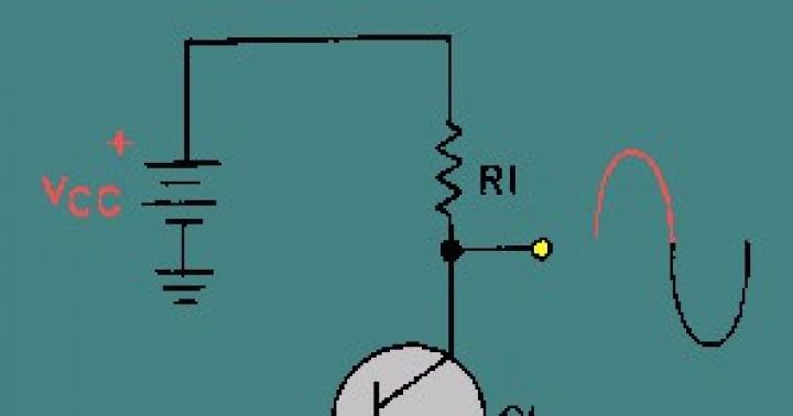
When charging, in the simplest case, a device called a “balancer” is placed at the output of the charger.
Next, in order not to write it myself, I’ll simply insert a piece of text from an article from the site http://www.os-propo.info/content/view/76/60/. We are talking about charging lithium batteries.
"The simplest type of balancer is a voltage limiter. It is a comparator that compares the voltage on the LiPo bank with a threshold value of 4.20 V. Upon reaching this value, a powerful transistor switch is opened, connected in parallel to the LiPo bank, passing through most of the charge current (1A or more) and converting the energy into heat. In this case, the can itself receives an extremely small part of the current, which practically stops its charge, allowing its neighbors to recharge. In fact, voltage equalization on battery cells with such a balancer occurs only at the end of the charge when the cells reach a threshold value.
In such a scheme, the task of charging and leveling a pair of different packs is actually feasible. But in practice such balancers are only homemade. All branded microprocessor balancers use a different operating principle.
Instead of dissipating the full charge currents at the end, the microprocessor balancer continuously monitors the bank voltages and gradually equalizes them throughout the charging process. To the jar that is charged more than others, the balancer connects in parallel some resistance (about 50-80 Ohms in most balancers), which passes part of the charging current through itself and only slightly slows down the charge of this jar, without stopping it completely. Unlike a transistor on a radiator, which is capable of taking on the main charge current, this resistance provides only a small balancing current - about 100 mA, and therefore such a balancer does not require massive radiators. It is this balancing current that is indicated in the technical characteristics of the balancers and is usually no more than 100-300mA.
Such a balancer does not heat up significantly, since the process continues throughout the entire charge, and the heat at low currents has time to dissipate without radiators. Obviously, if the charging current is significantly higher than the balancing current, then if there is a large spread of voltages across the banks, the balancer will not have time to equalize them before the most charged bank reaches the threshold voltage."
End of quote.
An example of a working diagram of a simple balancer can be the following (taken from the website http://www.zajic.cz/).

Fig.1. A simple balancer circuit.
In fact, this is a powerful zener diode, by the way, very accurate, loaded with a low-resistance load, the role of which is played here by diodes D2...D5. Microcircuit D1 measures the voltage at the plus and minus of the battery and if it rises above the threshold, it opens the powerful transistor T1, passing all the current from the charger through itself.

Fig.2. A simple balancer circuit.
The second circuit works similarly (Fig. 2), but in it all the heat is released in transistor T1, which heats up like a “kettle” - the radiator can be seen in the picture below.

In Fig. 3 it can be seen that the balancer consists of 3 channels, each of which is made according to the scheme in Fig. 2.
Of course, the industry has long mastered such circuits, which are produced in the form of a complete microcircuit. Many companies produce them. As an example, I will use the materials of the article on balancing methods published on the RadioLotsman website http://www.rlocman.ru/shem/schematics.html?di=59991, which I will partially change or remove so as not to bloat the article.
Quote:
" Passive balancing method.
The simplest solution is to equalize the battery voltage. For example, the BQ77PL900 chip provides protection for battery packs with 5-10 batteries connected in series. The microcircuit is a functionally complete unit and can be used to work with a battery compartment, as shown in Figure 4. Comparing the voltage of the bank with the threshold, the microcircuit, if necessary, turns on the balancing mode for each of the banks.


Fig.4. Chip BQ77PL900, and the second analogue, where the internal structure is better visible (taken from here http://qrx.narod.ru/bp/bat_v.htm ).
In Fig. Figure 5 shows the principle of its operation. If the voltage of any battery exceeds a predetermined threshold, the field-effect transistors are turned on and a load resistor is connected in parallel to the battery cell, through which the current bypasses the cell and no longer charges it. The remaining cells continue to charge.
When the voltage drops, the field switch closes and charging can continue. Thus, at the end of charging, the same voltage will be present on all cells.
When applying a balancing algorithm that uses only voltage deviation as a criterion, incomplete balancing is possible due to the difference in the internal resistance of the batteries (see Fig. 6.). The fact is that part of the voltage drops across this resistance when current flows through the battery, which introduces an additional error into the voltage spread during charging.
The battery protection chip cannot determine whether the imbalance is caused by different battery capacities or differences in their internal resistances. Therefore, with this type of passive balancing there is no guarantee that all batteries will be 100% charged.
The BQ2084 chip uses an improved version of balancing, also based on voltage changes, but in order to minimize the effect of internal resistance variation, the BQ2084 performs balancing closer to the end of the charging process, when the charging current is low.
Rice. 5. Passive method based on voltage balancing.

Rice. 6. Passive voltage balancing method.
Microcircuits of the BQ20Zхх family use proprietary Impedance Track technology to determine the charge level, based on determining the state of charge of the batteries (SBC) and battery capacity.
In this technology, for each battery the charge Qneed required to fully charge it is calculated, after which the difference?Q between the Qneed of all batteries is found. The chip then turns on power switches that discharge all cells to the level of the least charged until the charges are equalized
Due to the fact that the difference in the internal resistance of the batteries does not affect this method, it can be used at any time, both when charging and discharging the battery. However, as mentioned above, it is stupid to use this method when discharging, because there is always not enough energy.
The main advantage of this technology is more accurate battery balancing (see Figure 7) compared to other passive methods.

Rice. 7. Passive balancing based on SZB and capacitance.
Active balancing
In terms of energy efficiency, this method is superior to passive balancing, because To transfer energy from a more charged cell to a less charged one, instead of resistors, inductances and capacitances are used, in which there is practically no energy loss. This method is preferred in cases where maximum battery life is required.
Featuring proprietary PowerPump technology, the BQ78PL114 is TI's latest active battery balancing component and uses an inductive converter to transfer power.
PowerPump uses n-channel p-channel FETs and an inductor that is located between a pair of batteries. The circuit is shown in Fig. 8. The field switches and inductor make up a buck/boost converter.
For example, if the BQ78PL114 determines that the upper cell is more charged than the lower one, then a signal is generated at the PS3 pin that opens transistor Q1 with a frequency of about 200 kHz and a duty cycle of about 30%.
With Q2 closed, a standard buck switching regulator circuit is obtained, with the internal diode of Q2 shorting the inductor current while Q1 is closed.
When pumping from the lower cell to the upper one, when only key Q2 opens, we also get a typical circuit, but this time of a step-up pulse stabilizer.
Keys Q1 and Q2, of course, should never be opened at the same time.

Rice. 8. Balancing using PowerPump technology.
In this case, energy losses are small and almost all the energy flows from a highly charged to a weakly charged jar. The BQ78PL114 chip implements three balancing algorithms:
- by voltage at the battery terminals. This method is similar to the passive balancing method described above, but there is almost no loss;
- by open circuit voltage. This method compensates for differences in the internal resistance of batteries;
- according to the battery charge state (based on predicting the battery state). The method is similar to that used in the BQ20Zxx family of microcircuits for passive balancing by SSB and battery capacity. In this case, the charge that needs to be transferred from one battery to another is precisely determined. Balancing occurs at the end of the charge. When using this method, the best result is achieved (see Fig. 9.)
Rice. 9. Active balancing according to the algorithm for equalizing the battery charge state.
Due to the large balancing currents, PowerPump technology is much more efficient than conventional passive balancing with energy dissipation. When balancing a laptop battery pack, the balancing currents are 25...50 mA. By selecting the value of the components, you can achieve balancing efficiency 12-20 times better than with the passive method with internal keys. A typical unbalance value (less than 5%) can be achieved in just one or two cycles.
In addition, PowerPump technology has other advantages: balancing can occur in any operating mode - charge, discharge, and even when the battery delivering energy has a lower voltage than the battery receiving energy." (End of partial quotation.)
Let's continue the description of active methods of transferring charge from one cell to another with the following circuit, which I found on the Internet on the website "HamRadio" http://qrx.narod.ru/bp/bat_v.htm.
A capacitive storage device, rather than an inductive one, is used as a charge pumping circuit. For example, so-called voltage converters based on switched capacitors are widely known. One of the popular ones is the ICL7660 microcircuit (MAX1044 or the domestic analogue KR1168EP1).
Basically, the microcircuit is used to obtain a negative voltage equal to its supply voltage. However, if for some reason the negative voltage at its output turns out to be greater in magnitude than the positive supply voltage, then the microcircuit will begin to pump charge “in the opposite direction,” taking it from the negative and giving it to the positive, i.e. she is constantly trying to equalize these two tensions.
This property is used to balance two battery cells. The diagram of such a balancer is shown in Fig. 10.

Fig. 10. Balancer circuit with capacitive charge pumping.
The high frequency chip connects capacitor C1 to either the upper battery G1 or the lower battery G2. Accordingly, C1 will be charged from a more charged one and discharged into a more discharged one, each time transferring some portion of the charge.
Over time, the voltages on the batteries will become the same.
The energy in the circuit is practically not dissipated; the efficiency of the circuit can reach up to 95...98% depending on the voltage on the batteries and the output current, which depends on the switching frequency and capacity C1.
At the same time, the actual consumption of the microcircuit is only a few tens of microamps, i.e. is below the self-discharge level of many batteries, and therefore the microcircuit does not even need to be disconnected from the battery and it will constantly slowly do the job of equalizing the voltage on the cells.
In reality, the pumping current can reach 30...40mA, but the efficiency decreases. Typically tens of mA. Also, the supply voltage can be from 1.5 to 10V, which means that the microcircuit can balance both ordinary Ni-Mh fingers and lithium batteries.
Practical note: in Fig.10. shows a circuit that balances batteries with a voltage of less than 3V, so its sixth leg (LV) is connected to output 3. To balance lithium batteries with a higher voltage, pin 6 should be left free and not connected anywhere.
Also, with this method it is possible to balance not only two, but also a larger number of batteries. In Fig.11. shows how to do this.

Fig. 11. Cascading of charge transfer microcircuits.
Well, and finally, another circuit solution that implements capacitive charge transfer from one battery to another.
If the ICL7660 was a multiplexer that could connect capacitor C1 to only two sources, then taking a multiplexer with a large number of switching channels (3, 4, 8) you can equalize voltages on three, four or eight banks with one chip. Moreover, the banks can be connected in any way, either in series or in parallel. The main thing is that the supply voltage of the microcircuit is higher than the maximum voltage on the banks.
The circuit of the so-called “reversible voltage converter”, described in the magazine “Radio” 1989, No. 8, is shown in Fig. 12.

Fig. 12. Reversible voltage converter as a balancer on the multiplexer 561KP1..
Up to four elements can be connected to the leveling device. Capacitor C2 is alternately connected to various elements, ensuring the transfer of energy from these elements and equalizing the voltage on them
The number of cells in the battery may be reduced. In this case, instead of the excluded elements, it is enough to connect a capacitor with a capacity of 10..20 μF.
The balancing current of such a source is very small, up to 2 mA. But since it works constantly, without being disconnected from the batteries, it fulfills its task - equalizing the charges of the cells.
In conclusion, I would like to note that the modern element base makes it possible to balance the cells of a composite battery with virtually no losses and is already simple enough to cease to be something “cool” and inaccessible.
And therefore, a radio amateur who designs battery-powered devices should think about switching to active methods of transferring energy between banks in a battery, at least the “old-fashioned way”, focusing on the equality of voltages between battery cells, and not the charges in them.
All articles on the site are permitted to be copied, but with the obligatory indication of a link to us.
Surely, every radio amateur has encountered a problem when connecting lithium batteries in series, he noticed that one runs out quickly and the other still holds a charge, but because of the other one, the entire battery does not produce the required voltage. This happens because when charging the entire battery pack, they are not charged evenly, and some batteries gain full capacity while others do not. This leads not only to rapid discharge, but also to failure of individual elements due to constant insufficient charging.
Fixing the problem is quite simple; each battery cell requires a so-called balancer, a device that, after the battery is fully charged, blocks its further recharging, and uses a control transistor to pass the charging current past the cell.
The balancer circuit is quite simple, assembled on a precision controlled zener diode TL431A and a direct conduction transistor BD140.

After much experimentation, the circuit changed a little, 3 1N4007 diodes connected in series were installed in place of the resistors, the balancer, in my opinion, became more stable, the diodes get noticeably warm when charging, this should be taken into account when laying out the board.

Principle of operation very simple, as long as the voltage on the element is less than 4.2 volts, charging is in progress, the controlled zener diode and transistor are closed and do not affect the charging process. As soon as the voltage reaches 4.2 volts, the zener diode begins to open the transistor, which shunts the battery through resistors with a total resistance of 4 Ohms, thereby preventing the voltage from rising above the upper threshold of 4.2 volts, and allows the remaining batteries to charge. A transistor with resistors calmly passes a current of about 500 mA, while it heats up to 40-45 degrees. As soon as the LED on the balancer lights up, the battery connected to it is fully charged. That is, if you have 3 batteries connected, then the end of the charge should be considered the lighting of the LEDs on all three balancers.
Settings It’s very simple, we apply a voltage of 5 volts to the board (without a battery) through a resistor of approximately 220 Ohms, and measure the voltage on the board, it should be 4.2 volts, if it differs, then we select a 220 kOhm resistor within small limits.
The voltage for charging needs to be supplied approximately 0.1-0.2 volts more than the voltage on each element in the charged state, example: we have 3 batteries connected in series, 4.2 volts each in the charged state, the total voltage is 12.6 volts. 12.6 + 0.1 + 0.1 + 0.1 = 12.9 volts. You should also limit the charge current to 0.5 A.
As an option for a voltage and current stabilizer, you can use the LM317 microcircuit, the connection is standard from the datasheet, the circuit looks like this.

The transformer must be selected based on the calculation - the voltage of the charged battery + 3 volts according to the variable, for the correct operation of the LM317. Example: you have a 12.6 volt + 3 volt battery = a transformer needs 15-16 volt alternating voltage.
Since LM317 is a linear regulator, and the voltage drop across it will turn into heat, we must install it on a radiator.
Now a little about how to calculate the divisor R3-R4 for voltage stabilization, but very simply according to the formula R3+R4=(Vo/1.25-1)*R2, the Vo value is the end-of-charge voltage (maximum output after the stabilizer).
Example: we need to get 12.9 volts output for 3. batteries with balancers. R3+R4=(12.9/1.25-1)*240=2476.8 Ohm. which is approximately equal to 2.4 kOhm + we have a trimming resistor for precise adjustment (470 Ohms), which will allow us to easily set the calculated output voltage.
Now calculate the output current, the resistor Ri is responsible for it, the formula is simple Ri=0.6/Iз, where Iз is the maximum charge current. Example: we need a current of 500 mA, Ri=0.6/0.5A= 1.2 Ohm. It should be taken into account that a charging current flows through this resistor, so its power should be 2 W. That's all, I'm not posting the boards, they will be when I assemble a charger with a balancer for my metal detector.
Nowadays lithium batteries are gaining more and more popularity. Especially finger ones, like 18650 , at 3.7 V 3000 mA. I have no doubt that in another 3-5 years they will completely replace nickel-cadmium. True, the question about their charging remains open. If everything is clear with old batteries - collect them in a battery and through a resistor to any suitable power supply, then this trick does not work here. But how then can you charge several pieces at once without using expensive branded balancing chargers?
Theory
To connect batteries in series, usually the positive terminal of the first battery in series is connected to the positive terminal of the electrical circuit. The positive terminal of the second battery is connected to its negative terminal, etc. The negative terminal of the last battery is connected to the negative terminal of the unit. The resulting battery in series connection has the same capacity as a single battery, and the voltage of such a battery is equal to the sum of the voltages of the batteries included in it. This means that if the batteries have the same voltage, then the battery voltage is equal to the voltage of one battery multiplied by the number of batteries in the battery.
The energy accumulated in the battery is equal to the sum of the energies of the individual batteries (the product of the energies of the individual batteries, if the batteries are the same), regardless of whether the batteries are connected in parallel or in series.
Lithium-ion batteries cannot simply be connected to a power supply unit - the charging currents on each element (bank) must be equalized. Balancing is carried out when charging the battery, when there is a lot of energy and it can not be saved much, and therefore, without any significant losses, you can use the passive dissipation of “excess” electricity.
Nickel-cadmium batteries do not require additional systems, since each link, when its maximum charge voltage is reached, stops receiving energy. Signs of a Ni-Cd being fully charged are an increase in voltage to a certain value, and then a drop of several tens of millivolts, and an increase in temperature - so that the excess energy immediately turns into heat.
The opposite is true for lithium batteries. Discharge to low voltages causes degradation of the chemistry and irreversible damage to the element, with an increase in internal resistance. In general, they are not protected from overcharging, and you can waste a lot of extra energy, thereby dramatically reducing their service life.
If we connect several lithium cells in a row and feed them through clamps at both ends of the block, then we cannot control the charge of individual cells. It is enough that one of them will have a slightly higher resistance or a slightly lower capacitance, and this link will reach a charge voltage of 4.2 V much faster, while the rest will still have 4.1 V. And when the voltage of the entire package reaches charge voltage, it may be that these weak links are charged to 4.3 Volts or even more. With each such cycle, the parameters will deteriorate. In addition, Li-Ion is unstable and, if overloaded, can reach high temperatures and, consequently, explode.

Most often, a device called a “balancer” is installed at the output of the charging voltage source. The simplest type of balancer is a voltage limiter. It is a comparator that compares the voltage on a Li-Ion bank with a threshold value of 4.20 V. Upon reaching this value, a powerful transistor switch is opened, connected in parallel to the element, passing most of the charge current through itself and converting the energy into heat. In this case, the can itself receives an extremely small part of the current, which practically stops its charge, allowing its neighbors to recharge. The voltage equalization on the battery cells with such a balancer occurs only at the end of the charge when the elements reach a threshold value.
Simplified diagram of a balancer for a battery

Here is a simplified circuit diagram of a current balancer based on the TL431. Resistors R1 and R2 set the voltage to 4.20 Volts, or you can choose others depending on the type of battery. The reference voltage for the regulator is removed from the transistor, and already at the border of 4.20 V, the system will begin to open the transistor slightly to prevent exceeding the specified voltage. A minimal increase in voltage will cause the transistor current to increase very quickly. During tests, already at 4.22 V (an increase of 20 mV), the current was more than 1 A.

In principle, any PNP transistor operating in the range of voltages and currents that interests us is suitable here. If the batteries are to be charged with a current of 500 mA. The calculation of its power is simple: 4.20 V x 0.5 A = 2.1 V, and this is how much the transistor must lose, which will probably require some cooling. For a charging current of 1 A or more, the power loss increases accordingly, and it will become increasingly difficult to get rid of the heat. During the test, several different transistors were tested, in particular BD244C, 2N6491 and A1535A - they all behave the same.

The voltage divider R1 and R2 should be selected so as to obtain the desired clamping voltage. For convenience, here are a few values, after applying which we will get the following results:
- R1 + R2 = Vo
- 22K + 33K = 4.166 V
- 15K + 22K = 4.204 V
- 47K + 68K = 4.227 V
- 27K + 39K = 4.230 V
- 39K + 56K = 4.241 V
- 33K + 47K = 4.255 V

This is an analogue of a powerful zener diode loaded with a low-resistance load, the role of which here is played by diodes D2...D5. Microcircuit D1 measures the voltage at the plus and minus of the battery and if it rises above the threshold, it opens a powerful transistor, passing all the current from the charger through itself. How all this is connected together and to the power supply - see below.

The blocks turn out to be really small, and you can safely install them directly on the element. You just need to keep in mind that the potential of the negative pole of the battery arises on the transistor body, and you must be careful when installing common radiator systems - you must use insulation of the transistor bodies from each other.
Tests
Immediately 6 pieces of balancing blocks were needed to simultaneously charge 6 18650 batteries. The elements are visible in the photo below.

All elements were charged exactly to 4.20 volts (the voltage was set by potentiometers), and the transistors became hot, although there was no additional cooling - charging with a current of 500 mA. Thus, we can safely recommend this method for simultaneous charging of several lithium batteries from a common voltage source.
Discuss the article SIMULTANEOUS CHARGING OF SEVERAL BATTERIES
Of course, separate charge. But this is only for my specific case.
Often you have to work in the field without a network; a screwdriver is always at hand. The batteries were already old and needed improvement. I shook out the dead NiCds from the screwdriver cartridges and stuffed them into both LiPo cases, each holding 5 cans. It’s a blunder, but you also need to charge it in the field or in the car, and it’s advisable to charge it with balancing, because all 5 cans in each account behave differently, which is affected by the ketai. Balancing during charging can be done in different ways, there are countless ways. The simplest is to brake the recharged cans with a load and transfer them to heat. This is what the desktop IMAX B6 does, but I don’t like that it takes a long time to charge the entire battery when balancing is turned on.
I figured it out and thought that the easiest way in terms of circuit design would be to charge each cell in the battery separately. Somehow, while Googling balancing methods, I came across a similar idea:
"Bloody cheaters... When I was thinking about this, I was going to build a bunch of DCDC"s where voltage of each contact is individually controlled => each cell might be charged with individual charge plan. Apparently, this is just too complex. "
But it seemed less complicated to me: we make a DC-DC with 5 outputs and attach a charger microcircuit to each one, of which there are a legion for Li-Ion! And, I thought, there should be less heat: there’s no need to slow down the banks! (Yeah, right now, the charging mikruhs are heating up like bastards!)
Here is a diagram drawn:
The circuit is simple, the only problem was with the choice of transistor. With a broad gesture, I first plugged in the IRLS3034, whose shutter capacity was too much for the LM3478 driver, so I had to install something less flashy. For each channel - an STC4054G, a cheap option that satisfies the task. Here is the assembled board, spread out in one layer: 
The manufacturer of the STC4054G charging chip recommends making the tracks on the board as thick as possible and, if possible, using polygons on both sides of the board for heat dissipation. I didn’t listen to the idiot, but in vain: the mikruhi heat up as they should, even with the charge current set at 400 mA per can.
And from another angle: 
Charges and heats up, infection: 
Well, if it gets hot, it needs to be cooled. I selected a convenient aluminum case, drilled the cover for connectors, fasteners and LEDs. Round holes - with a round cutter, rectangular - with a rectangular one) 
Assembled and ready to sail: 
There was an idea to paint it black, but I was too lazy. And this is pampering - this hedgehog is destined to live in the car under his feet, closer to the cigarette lighter.

Next time I'll think about balancing. I really like the idea of a Robinhood transformer that takes from rich banks and gives it to the poor banks in a battery. It seems like the efficiency is higher and there is less heat. But again, the rich batteries are milked back and forth until the poor ones fill up; This isn't very good, is it?
UPD: According to transformer parameters and ratings. The transformer wound on a not very good core, what was at hand, 2 x MP140-1, KP19x11x4.8. The primary is 21 turns of 0.35 wire, the secondary is simultaneously 11 turns of 0.51 wire. Frequency setting R1C1 - at ~100 kHz, 4.7 kOhm/0.1 µF. The feedback divider R2R3 is 21 kOhm/8.2 kOhm. R4 - 75 kOhm, shunt R5R6 - 0.1 Ohm each (total 0.05 Ohm). VD1 - SMBJ15, VD2 - SM4005. VD4 is some kind of Schottky from 1 A, C5 - 330 µF x 25V, VD8 - 5V1 zener diode, C10 - 0.1 µF. R7 - 470 Ohm, R12 - 2 kOhm, which gives approximately 400 mA.
Assessing the characteristics of a particular charger is difficult without understanding how an exemplary charge of a li-ion battery should actually proceed. Therefore, before moving directly to the diagrams, let's remember a little theory.
What are lithium batteries?
Depending on what material the positive electrode of a lithium battery is made of, there are several varieties:
- with lithium cobaltate cathode;
- with a cathode based on lithiated iron phosphate;
- based on nickel-cobalt-aluminium;
- based on nickel-cobalt-manganese.
All of these batteries have their own characteristics, but since these nuances are not of fundamental importance for the general consumer, they will not be considered in this article.
Also, all li-ion batteries are produced in various sizes and form factors. They can be either cased (for example, the popular 18650 today) or laminated or prismatic (gel-polymer batteries). The latter are hermetically sealed bags made of a special film, which contain electrodes and electrode mass.
The most common sizes of li-ion batteries are shown in the table below (all of them have a nominal voltage of 3.7 volts):
| Designation | Standard size | Similar size |
|---|---|---|
| XXYY0, Where XX- indication of diameter in mm, YY- length value in mm, 0 - reflects the design in the form of a cylinder |
10180 | 2/5 AAA |
| 10220 | 1/2 AAA (Ø corresponds to AAA, but half the length) | |
| 10280 | ||
| 10430 | AAA | |
| 10440 | AAA | |
| 14250 | 1/2 AA | |
| 14270 | Ø AA, length CR2 | |
| 14430 | Ø 14 mm (same as AA), but shorter length | |
| 14500 | AA | |
| 14670 | ||
| 15266, 15270 | CR2 | |
| 16340 | CR123 | |
| 17500 | 150S/300S | |
| 17670 | 2xCR123 (or 168S/600S) | |
| 18350 | ||
| 18490 | ||
| 18500 | 2xCR123 (or 150A/300P) | |
| 18650 | 2xCR123 (or 168A/600P) | |
| 18700 | ||
| 22650 | ||
| 25500 | ||
| 26500 | WITH | |
| 26650 | ||
| 32650 | ||
| 33600 | D | |
| 42120 |
Internal electrochemical processes proceed in the same way and do not depend on the form factor and design of the battery, so everything said below applies equally to all lithium batteries.
How to properly charge lithium-ion batteries
The most correct way to charge lithium batteries is to charge in two stages. This is the method Sony uses in all of its chargers. Despite a more complex charge controller, this ensures a more complete charge of li-ion batteries without reducing their service life.
Here we are talking about a two-stage charge profile for lithium batteries, abbreviated as CC/CV (constant current, constant voltage). There are also options with pulse and step currents, but they are not discussed in this article. You can read more about charging with pulsed current.
So, let's look at both stages of charging in more detail.
1. At the first stage A constant charging current must be ensured. The current value is 0.2-0.5C. For accelerated charging, it is allowed to increase the current to 0.5-1.0C (where C is the battery capacity).
For example, for a battery with a capacity of 3000 mAh, the nominal charge current at the first stage is 600-1500 mA, and the accelerated charge current can be in the range of 1.5-3A.
To ensure a constant charging current of a given value, the charger circuit must be able to increase the voltage at the battery terminals. In fact, at the first stage the charger works as a classic current stabilizer.
Important: If you plan to charge batteries with a built-in protection board (PCB), then when designing the charger circuit you need to make sure that the open circuit voltage of the circuit can never exceed 6-7 volts. Otherwise, the protection board may be damaged.
At the moment when the voltage on the battery rises to 4.2 volts, the battery will gain approximately 70-80% of its capacity (the specific capacity value will depend on the charging current: with accelerated charging it will be a little less, with a nominal charge - a little more). This moment marks the end of the first stage of charging and serves as a signal for the transition to the second (and final) stage.
2. Second charge stage- this is charging the battery with a constant voltage, but a gradually decreasing (falling) current.
At this stage, the charger maintains a voltage of 4.15-4.25 volts on the battery and controls the current value.
As the capacity increases, the charging current will decrease. As soon as its value decreases to 0.05-0.01C, the charging process is considered complete.
An important nuance of the correct charger operation is its complete disconnection from the battery after charging is complete. This is due to the fact that for lithium batteries it is extremely undesirable for them to remain under high voltage for a long time, which is usually provided by the charger (i.e. 4.18-4.24 volts). This leads to accelerated degradation of the chemical composition of the battery and, as a consequence, a decrease in its capacity. Long-term stay means tens of hours or more.
During the second stage of charging, the battery manages to gain approximately 0.1-0.15 more of its capacity. The total battery charge thus reaches 90-95%, which is an excellent indicator.
We looked at two main stages of charging. However, coverage of the issue of charging lithium batteries would be incomplete if another charging stage were not mentioned - the so-called. precharge.
Preliminary charge stage (precharge)- this stage is used only for deeply discharged batteries (below 2.5 V) to bring them to normal operating mode.
At this stage, the charge is provided with a reduced constant current until the battery voltage reaches 2.8 V.
The preliminary stage is necessary to prevent swelling and depressurization (or even explosion with fire) of damaged batteries that have, for example, an internal short circuit between the electrodes. If a large charge current is immediately passed through such a battery, this will inevitably lead to its heating, and then it depends.
Another benefit of precharging is pre-heating the battery, which is important when charging at low ambient temperatures (in an unheated room during the cold season).
Intelligent charging should be able to monitor the voltage on the battery during the preliminary charging stage and, if the voltage does not rise for a long time, draw a conclusion that the battery is faulty.
All stages of charging a lithium-ion battery (including the pre-charge stage) are schematically depicted in this graph: 
Exceeding the rated charging voltage by 0.15V can reduce the battery life by half. Lowering the charge voltage by 0.1 volt reduces the capacity of a charged battery by about 10%, but significantly extends its service life. The voltage of a fully charged battery after removing it from the charger is 4.1-4.15 volts.
Let me summarize the above and outline the main points:
1. What current should I use to charge a li-ion battery (for example, 18650 or any other)?
The current will depend on how quickly you would like to charge it and can range from 0.2C to 1C.
For example, for a battery size 18650 with a capacity of 3400 mAh, the minimum charge current is 680 mA, and the maximum is 3400 mA.
2. How long does it take to charge, for example, the same 18650 batteries?
The charging time directly depends on the charging current and is calculated using the formula:
T = C / I charge.
For example, the charging time of our 3400 mAh battery with a current of 1A will be about 3.5 hours.
3. How to properly charge a lithium polymer battery?
All lithium batteries charge the same way. It doesn't matter whether it is lithium polymer or lithium ion. For us, consumers, there is no difference.
What is a protection board?
The protection board (or PCB - power control board) is designed to protect against short circuit, overcharge and overdischarge of the lithium battery. As a rule, overheating protection is also built into the protection modules.
For safety reasons, it is prohibited to use lithium batteries in household appliances unless they have a built-in protection board. That's why all cell phone batteries always have a PCB board. The battery output terminals are located directly on the board: 
These boards use a six-legged charge controller on a specialized device (JW01, JW11, K091, G2J, G3J, S8210, S8261, NE57600 and other analogues). The task of this controller is to disconnect the battery from the load when the battery is completely discharged and disconnect the battery from charging when it reaches 4.25V.
Here, for example, is a diagram of the BP-6M battery protection board that was supplied with old Nokia phones: 
If we talk about 18650, they can be produced either with or without a protection board. The protection module is located near the negative terminal of the battery. 

The board increases the length of the battery by 2-3 mm. 
Batteries without a PCB module are usually included in batteries that come with their own protection circuits.
Any battery with protection can easily turn into a battery without protection; you just need to gut it. ![]()
Today, the maximum capacity of the 18650 battery is 3400 mAh. Batteries with protection must have a corresponding designation on the case ("Protected"). 
Do not confuse the PCB board with the PCM module (PCM - power charge module). If the former serve only the purpose of protecting the battery, then the latter are designed to control the charging process - they limit the charge current at a given level, control the temperature and, in general, ensure the entire process. The PCM board is what we call a charge controller.
I hope now there are no questions left, how to charge an 18650 battery or any other lithium battery? Then we move on to a small selection of ready-made circuit solutions for chargers (the same charge controllers).
Charging schemes for li-ion batteries
All circuits are suitable for charging any lithium battery; all that remains is to decide on the charging current and the element base.
LM317
Diagram of a simple charger based on the LM317 chip with a charge indicator: 
The circuit is the simplest, the whole setup comes down to setting the output voltage to 4.2 volts using trimming resistor R8 (without a connected battery!) and setting the charging current by selecting resistors R4, R6. The power of resistor R1 is at least 1 Watt.
As soon as the LED goes out, the charging process can be considered completed (the charging current will never decrease to zero). It is not recommended to keep the battery on this charge for a long time after it is fully charged.
The lm317 microcircuit is widely used in various voltage and current stabilizers (depending on the connection circuit). It is sold on every corner and costs pennies (you can take 10 pieces for only 55 rubles).
LM317 comes in different housings: 
Pin assignment (pinout): 
Analogues of the LM317 chip are: GL317, SG31, SG317, UC317T, ECG1900, LM31MDT, SP900, KR142EN12, KR1157EN1 (the last two are domestically produced).
The charging current can be increased to 3A if you take LM350 instead of LM317. It will, however, be more expensive - 11 rubles/piece.
The printed circuit board and circuit assembly are shown below: 

The old Soviet transistor KT361 can be replaced with a similar pnp transistor (for example, KT3107, KT3108 or bourgeois 2N5086, 2SA733, BC308A). It can be removed altogether if the charge indicator is not needed.
Disadvantage of the circuit: the supply voltage must be in the range of 8-12V. This is due to the fact that for normal operation of the LM317 chip, the difference between the battery voltage and the supply voltage must be at least 4.25 Volts. Thus, it will not be possible to power it from the USB port.
MAX1555 or MAX1551
MAX1551/MAX1555 are specialized chargers for Li+ batteries, capable of operating from USB or from a separate power adapter (for example, a phone charger).
 The only difference between these microcircuits is that MAX1555 produces a signal to indicate the charging process, and MAX1551 produces a signal that the power is on. Those. 1555 is still preferable in most cases, so 1551 is now difficult to find on sale.
A detailed description of these microcircuits from the manufacturer is.
The maximum input voltage from the DC adapter is 7 V, when powered by USB - 6 V. When the supply voltage drops to 3.52 V, the microcircuit turns off and charging stops.
The microcircuit itself detects at which input the supply voltage is present and connects to it. If the power is supplied via the USB bus, then the maximum charging current is limited to 100 mA - this allows you to plug the charger into the USB port of any computer without fear of burning the south bridge.
When powered by a separate power supply, the typical charging current is 280 mA.
The chips have built-in overheating protection. But even in this case, the circuit continues to operate, reducing the charge current by 17 mA for each degree above 110 ° C.
There is a pre-charge function (see above): as long as the battery voltage is below 3V, the microcircuit limits the charge current to 40 mA.
The microcircuit has 5 pins. Here is a typical connection diagram: 
If there is a guarantee that the voltage at the output of your adapter cannot under any circumstances exceed 7 volts, then you can do without the 7805 stabilizer.
The USB charging option can be assembled, for example, on this one. 
The microcircuit does not require either external diodes or external transistors. In general, of course, gorgeous little things! Only they are too small and inconvenient to solder. And they are also expensive ().
LP2951
The LP2951 stabilizer is manufactured by National Semiconductors (). It provides the implementation of a built-in current limiting function and allows you to generate a stable charge voltage level for a lithium-ion battery at the output of the circuit.
The charge voltage is 4.08 - 4.26 volts and is set by resistor R3 when the battery is disconnected. The voltage is kept very accurately.
The charge current is 150 - 300mA, this value is limited by the internal circuits of the LP2951 chip (depending on the manufacturer).
Use the diode with a small reverse current. For example, it can be any of the 1N400X series that you can purchase. The diode is used as a blocking diode to prevent reverse current from the battery into the LP2951 chip when the input voltage is turned off. 
This charger produces a fairly low charging current, so any 18650 battery can charge overnight.
The microcircuit can be purchased both in a DIP package and in a SOIC package (costs about 10 rubles per piece).
MCP73831
The chip allows you to create the right chargers, and it’s also cheaper than the much-hyped MAX1555. 
A typical connection diagram is taken from: 
An important advantage of the circuit is the absence of low-resistance powerful resistors that limit the charge current. Here the current is set by a resistor connected to the 5th pin of the microcircuit. Its resistance should be in the range of 2-10 kOhm.
The assembled charger looks like this: 
The microcircuit heats up quite well during operation, but this does not seem to bother it. It fulfills its function.
Here is another version of a printed circuit board with an SMD LED and a micro-USB connector: 
LTC4054 (STC4054)
Very simple scheme, great option! Allows charging with current up to 800 mA (see). True, it tends to get very hot, but in this case the built-in overheating protection reduces the current. 
The circuit can be significantly simplified by throwing out one or even both LEDs with a transistor. Then it will look like this (you must admit, it couldn’t be simpler: a couple of resistors and one condenser): 
One of the printed circuit board options is available at . The board is designed for elements of standard size 0805.
I=1000/R. You shouldn’t set a high current right away; first see how hot the microcircuit gets. For my purposes, I took a 2.7 kOhm resistor, and the charge current turned out to be about 360 mA.
It is unlikely that it will be possible to adapt a radiator to this microcircuit, and it is not a fact that it will be effective due to the high thermal resistance of the crystal-case junction. The manufacturer recommends making the heat sink “through the leads” - making the traces as thick as possible and leaving the foil under the chip body. In general, the more “earth” foil left, the better.
By the way, most of the heat is dissipated through the 3rd leg, so you can make this trace very wide and thick (fill it with excess solder). 
The LTC4054 chip package may be labeled LTH7 or LTADY.
LTH7 differs from LTADY in that the first can lift a very low battery (on which the voltage is less than 2.9 volts), while the second cannot (you need to swing it separately).
The chip turned out to be very successful, so it has a bunch of analogues: STC4054, MCP73831, TB4054, QX4054, TP4054, SGM4054, ACE4054, LP4054, U4054, BL4054, WPM4054, IT4504, Y1880, PT6102, PT6181, VS61 02, HX6001, LC6000, LN5060, CX9058, EC49016, CYT5026, Q7051. Before using any of the analogues, check the datasheets.
TP4056
The microcircuit is made in a SOP-8 housing (see), it has a metal heat sink on its belly that is not connected to the contacts, which allows for more efficient heat removal. Allows you to charge the battery with a current of up to 1A (the current depends on the current-setting resistor). 
The connection diagram requires the bare minimum of hanging elements: 
The circuit implements the classical charging process - first charging with a constant current, then with a constant voltage and a falling current. Everything is scientific. If you look at charging step by step, you can distinguish several stages:
- Monitoring the voltage of the connected battery (this happens all the time).
- Precharge phase (if the battery is discharged below 2.9 V). Charge with a current of 1/10 from the one programmed by the resistor R prog (100 mA at R prog = 1.2 kOhm) to a level of 2.9 V.
- Charging with a maximum constant current (1000 mA at R prog = 1.2 kOhm);
- When the battery reaches 4.2 V, the voltage on the battery is fixed at this level. A gradual decrease in the charging current begins.
- When the current reaches 1/10 of the one programmed by the resistor R prog (100 mA at R prog = 1.2 kOhm), the charger turns off.
- After charging is complete, the controller continues monitoring the battery voltage (see point 1). The current consumed by the monitoring circuit is 2-3 µA. After the voltage drops to 4.0V, charging starts again. And so on in a circle.
The charge current (in amperes) is calculated by the formula I=1200/R prog. The permissible maximum is 1000 mA.
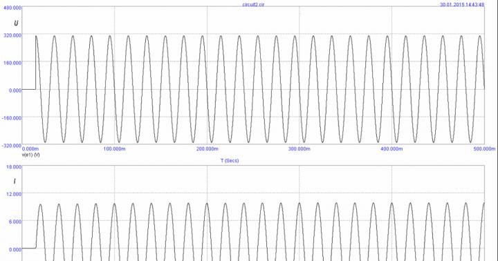
A real charging test with a 3400 mAh 18650 battery is shown in the graph: 
The advantage of the microcircuit is that the charge current is set by just one resistor. Powerful low-resistance resistors are not required. Plus there is an indicator of the charging process, as well as an indication of the end of charging. When the battery is not connected, the indicator blinks every few seconds.
The supply voltage of the circuit should be within 4.5...8 volts. The closer to 4.5V, the better (so the chip heats up less).
The first leg is used to connect a temperature sensor built into the lithium-ion battery (usually the middle terminal of a cell phone battery). If the output voltage is below 45% or above 80% of the supply voltage, charging is suspended. If you don't need temperature control, just plant that foot on the ground.
Attention! This circuit has one significant drawback: the absence of a battery reverse polarity protection circuit. In this case, the controller is guaranteed to burn out due to exceeding the maximum current. In this case, the supply voltage of the circuit directly goes to the battery, which is very dangerous.
The signet is simple and can be done in an hour on your knee. If time is of the essence, you can order ready-made modules. Some manufacturers of ready-made modules add protection against overcurrent and overdischarge (for example, you can choose which board you need - with or without protection, and with which connector). 
You can also find ready-made boards with a contact for a temperature sensor. Or even a charging module with several parallel TP4056 microcircuits to increase the charging current and with reverse polarity protection (example).
LTC1734
Also a very simple scheme. The charging current is set by resistor R prog (for example, if you install a 3 kOhm resistor, the current will be 500 mA).
Microcircuits are usually marked on the case: LTRG (they can often be found in old Samsung phones). 
Any pnp transistor is suitable, the main thing is that it is designed for a given charging current.
There is no charge indicator on the indicated diagram, but on the LTC1734 it is said that pin “4” (Prog) has two functions - setting the current and monitoring the end of the battery charge. For example, a circuit with control of the end of charge using the LT1716 comparator is shown. 
The LT1716 comparator in this case can be replaced with a cheap LM358.
TL431 + transistor
It is probably difficult to come up with a circuit using more affordable components. The hardest part here is finding the TL431 reference voltage source. But they are so common that they are found almost everywhere (rarely does a power source do without this microcircuit). 
Well, the TIP41 transistor can be replaced with any other one with a suitable collector current. Even the old Soviet KT819, KT805 (or less powerful KT815, KT817) will do.
Setting up the circuit comes down to setting the output voltage (without a battery!!!) using a trim resistor at 4.2 volts. Resistor R1 sets the maximum value of the charging current.
This circuit fully implements the two-stage process of charging lithium batteries - first charging with direct current, then moving to the voltage stabilization phase and smoothly reducing the current to almost zero. The only drawback is the poor repeatability of the circuit (it is capricious in setup and demanding on the components used).
MCP73812
There is another undeservedly neglected microcircuit from Microchip - MCP73812 (see). Based on it, a very budget charging option is obtained (and inexpensive!). The whole body kit is just one resistor!
By the way, the microcircuit is made in a solder-friendly package - SOT23-5. 
The only negative is that it gets very hot and there is no charge indication. It also somehow doesn’t work very reliably if you have a low-power power source (which causes a voltage drop). 
In general, if the charge indication is not important for you, and a current of 500 mA suits you, then the MCP73812 is a very good option.
NCP1835
A fully integrated solution is offered - NCP1835B, providing high stability of the charging voltage (4.2 ±0.05 V).
Perhaps the only drawback of this microcircuit is its too miniature size (DFN-10 case, size 3x3 mm). Not everyone can provide high-quality soldering of such miniature elements. 
Among the undeniable advantages I would like to note the following:
- Minimum number of body parts.
- Possibility of charging a completely discharged battery (precharge current 30 mA);
- Determining the end of charging.
- Programmable charging current - up to 1000 mA.
- Charge and error indication (capable of detecting non-chargeable batteries and signaling this).
- Protection against long-term charging (by changing the capacitance of the capacitor C t, you can set the maximum charging time from 6.6 to 784 minutes).

The cost of the microcircuit is not exactly cheap, but also not so high (~$1) that you can refuse to use it. If you are comfortable with a soldering iron, I would recommend choosing this option.
A more detailed description is in.
Can I charge a lithium-ion battery without a controller?
Yes, you can. However, this will require close control of the charging current and voltage.
In general, it will not be possible to charge a battery, for example, our 18650, without a charger. You still need to somehow limit the maximum charge current, so at least the most primitive memory will still be required.
The simplest charger for any lithium battery is a resistor connected in series with the battery: 
The resistance and power dissipation of the resistor depend on the voltage of the power source that will be used for charging.
As an example, let's calculate a resistor for a 5 Volt power supply. We will charge an 18650 battery with a capacity of 2400 mAh.
So, at the very beginning of charging, the voltage drop across the resistor will be:
U r = 5 - 2.8 = 2.2 Volts
Let's say our 5V power supply is rated for a maximum current of 1A. The circuit will consume the highest current at the very beginning of the charge, when the voltage on the battery is minimal and amounts to 2.7-2.8 Volts.
Attention: these calculations do not take into account the possibility that the battery may be very deeply discharged and the voltage on it may be much lower, even to zero.
Thus, the resistor resistance required to limit the current at the very beginning of the charge at 1 Ampere should be:
R = U / I = 2.2 / 1 = 2.2 Ohm
Resistor power dissipation:
P r = I 2 R = 1*1*2.2 = 2.2 W
At the very end of the battery charge, when the voltage on it approaches 4.2 V, the charge current will be:
I charge = (U ip - 4.2) / R = (5 - 4.2) / 2.2 = 0.3 A
That is, as we see, all values do not go beyond the permissible limits for a given battery: the initial current does not exceed the maximum permissible charging current for a given battery (2.4 A), and the final current exceeds the current at which the battery no longer gains capacity ( 0.24 A).
The main disadvantage of such charging is the need to constantly monitor the voltage on the battery. And manually turn off the charge as soon as the voltage reaches 4.2 Volts. The fact is that lithium batteries tolerate even short-term overvoltage very poorly - the electrode masses begin to quickly degrade, which inevitably leads to loss of capacity. At the same time, all the prerequisites for overheating and depressurization are created.
If your battery has a built-in protection board, which was discussed just above, then everything becomes simpler. When a certain voltage is reached on the battery, the board itself will disconnect it from the charger. However, this charging method has significant disadvantages, which we discussed in.
The protection built into the battery will not allow it to be overcharged under any circumstances. All you have to do is control the charge current so that it does not exceed the permissible values for a given battery (protection boards cannot limit the charge current, unfortunately).
Charging using a laboratory power supply
If you have a power supply with current protection (limitation), then you are saved! Such a power source is already a full-fledged charger that implements the correct charge profile, which we wrote about above (CC/CV).
 All you need to do to charge li-ion is set the power supply to 4.2 volts and set the desired current limit. And you can connect the battery.
Initially, when the battery is still discharged, the laboratory power supply will operate in current protection mode (i.e., it will stabilize the output current at a given level). Then, when the voltage on the bank rises to the set 4.2V, the power supply will switch to voltage stabilization mode, and the current will begin to drop.
When the current drops to 0.05-0.1C, the battery can be considered fully charged.
As you can see, the laboratory power supply is an almost ideal charger! The only thing it can’t do automatically is make a decision to fully charge the battery and turn off. But this is a small thing that you shouldn’t even pay attention to.
How to charge lithium batteries?
And if we are talking about a disposable battery that is not intended for recharging, then the correct (and only correct) answer to this question is NO.
The fact is that any lithium battery (for example, the common CR2032 in the form of a flat tablet) is characterized by the presence of an internal passivating layer that covers the lithium anode. This layer prevents a chemical reaction between the anode and the electrolyte. And the supply of external current destroys the above protective layer, leading to damage to the battery.
By the way, if we talk about the non-rechargeable CR2032 battery, then the LIR2032, which is very similar to it, is already a full-fledged battery. It can and should be charged. Only its voltage is not 3, but 3.6V.
How to charge lithium batteries (be it a phone battery, 18650 or any other li-ion battery) was discussed at the beginning of the article.