The advent of semiconductors had a huge impact on the development of electronics: overall dimensions, as well as the price of components, decreased significantly. Diodes and transistors began to be introduced everywhere. One of these industries was relay technology, which, thanks to semiconductors, significantly expanded its range of applications.
The use of semiconductors has led to the emergence of a new class of relay technology - solid-state relays (SSRs). So, if in electromechanical relays a mechanical contact was used to open (close) the circuit, then in a new class of devices this function was taken over by transistors and thyristors (triacs). This replacement made it possible to avoid a number of significant shortcomings of electromechanical relays, such as: contact bounce, the occurrence of an arc discharge during switching, high switching time and low reliability. In addition, the use of a strapping circuit made it possible to add “intelligence” to the relay, i.e. implement a number of service functions: zero crossing control, presence of a status signal, etc. Moreover, all this has a fairly compact size. The use of semiconductors also made it possible to get away from electromagnetic isolation, replacing it with optoelectronic one, which made it possible to increase noise immunity.
The presence of all these advantages has made it possible to use TTP in various industries. Thus, the possibility of organizing the operation of a relay not when the control signal passes through zero, but at its maximum (amplitude) value, has strengthened the role of SSRs for switching inductive loads. This process differs from switching an active load in that at the moment the signal is supplied, a transient process begins to establish a stationary mode of the electrical circuit, in which the average current value over the period is zero. In this case, a constant component of the electric current appears in the circuit for the duration of the transient process, which depends on the inductance and resistance of the circuit (circuit time constant τ=L/R) (the circuit operates with magnetization for the duration of the transient process). The most undesirable moment of switching on is the moment the phase voltage passes through zero. In this case, the bias current and, accordingly, the amplitude of the current in the circuit has a maximum value. This mode can lead to saturation of the core (transformer, autotransformer, contactor winding, etc.). And as a result, a sharp decrease in inductance and, accordingly, a sharp increase in current (Fig. 1).
Figure 1 - transient process when the relay is turned on when the phase voltage passes through zero. τ is the time constant of the electrical circuit.
This can be avoided if you turn on the relay at the maximum amplitude Um) value of the alternating voltage (Fig. 2). As can be seen from the graph, this is achieved by shifting the phases of the current relative to the voltage by 90˚.

Figure 2 – transient process when the relay is turned on when the phase voltage passes through the maximum value of Um.
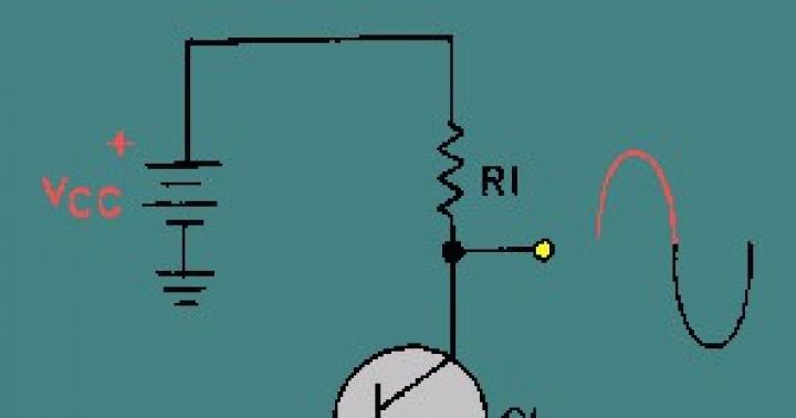
One of the options for solving this problem is the use of a semiconductor optoelectronic single-phase alternating current relay RPT-90, switched on at the maximum (amplitude Um) value of alternating voltage, produced by the domestic company Proton-Impulse CJSC (Fig. 3). The relay is made in a monolithic housing with dimensions 58.4x45.7x23.

Figure 3 – Overall and connection dimensions of the module
The relay is designed to connect active and active-inductive loads (transformer, autotransformer, electromagnetic contactor, etc.) to an alternating current network with a frequency f=50-60Hz, voltage Ud=100-400V. An alternating voltage from 7 to 278 V can serve as a control voltage. The connection diagram is shown in Figure 4.

Figure 4 – Connection diagram for the RPT-90 relay
This relay is universal, has IP 54 protection and allows you to switch both active and inductive loads with a current of up to 63 A. The technical characteristics of the relay are presented in Table 1.
Table 1. Main parameters of RPT-90

Conclusions:
In addition to the listed advantages, SSRs have increased reliability and operating time, which makes the presented relay a universal solution for the problem of switching circuits for active and inductive loads.
Controlling powerful loads is a fairly popular topic among people who are in one way or another concerned with home automation, and in general, regardless of the platform: be it Arduino, Rapsberry Pi, Unwired One or another platform, turn it on and off some kind of heater, boiler or a duct fan will have to be used sooner or later.
The traditional dilemma here is what to actually commute with. As many have learned from their sad experience, Chinese relays do not have the proper reliability - when switching a powerful inductive load, the contacts spark strongly, and at one point they may simply stick. You have to install two relays - the second one to protect against opening.
Instead of a relay, you can install a triac or solid-state relay (essentially the same thyristor or field-effect device with a logical signal control circuit and an optocoupler in one package), but they have another disadvantage - they heat up. Accordingly, a radiator is needed, which increases the dimensions of the structure.
I want to tell you about a simple and quite obvious, but at the same time rarely seen scheme that can do this:
Galvanic isolation of input and load
Switching of inductive loads without current and voltage surges
No significant heat generation even at maximum power
But first, a few illustrations. In all cases, TTI relays of the TRJ and TRIL series were used, and a 650 W vacuum cleaner was used as the load.
Classic scheme - we connect the vacuum cleaner through a regular relay. Then we connect an oscilloscope to the vacuum cleaner (Caution! Either the oscilloscope or the vacuum cleaner - or better yet, both - must be galvanically isolated from the ground! Don’t put your fingers or eggs in the salt shaker! They don’t joke with 220 V!) and take a look.
Include:
I had to reach almost the maximum mains voltage (trying to tie an electromagnetic relay to the zero crossing is a disastrous task: it is too slow). A short surge with almost vertical fronts boomed in both directions, and interference flew in all directions. Expected.
Turn off:
A sudden loss of voltage on an inductive load does not bode well - the surge will fly upward. In addition, do you see this noise on the sine wave milliseconds before the actual shutdown? This is the sparking of the relay contacts that have begun to open, which is why they will one day become stuck.
So, it is bad to switch an inductive load with a “naked” relay. What will we do? Let's try to add a snubber - an RC chain of a 120 Ohm resistor and a 0.15 µF capacitor.
Include:
Better, but not much. The ejection decreased in height, but was generally preserved.
Turn off:
Same picture. The debris remained, moreover, the sparking of the relay contacts remained, although greatly reduced.
Conclusion: with a snubber it is better than without a snubber, but it does not solve the problem globally. However, if you want to switch inductive loads with a regular relay, install a snubber. The ratings must be selected for a specific load, but a 1-W resistor at 100-120 Ohms and a capacitor at 0.1 µF seem to be a reasonable option for this case.
Related literature: Agilent - Application Note 1399, “Maximizing the Life Span of Your Relays.” When operating the relay on the worst type of load - a motor, which, in addition to inductance, also has a very low resistance at start - good authors recommend reducing the relay's rating life by five times.
Now let’s make a knight’s move - we will combine a triac, a triac driver with zero detection and a relay into one circuit.
What's in this diagram? On the left is the entrance. When “1” is applied to it, capacitor C2 is almost instantly charged through R1 and the lower half of D1; Optorelay VO1 turns on, waits for the nearest zero crossing (MOC3063 - with built-in zero detector circuit) and turns on triac D4. The load starts.
Capacitor C1 is charged through a chain of R1 and R2, which takes approximately t=RC ~ 100 ms. These are several periods of mains voltage, that is, during this time the triac will have time to turn on, guaranteed. Next, Q1 opens and relay K1 turns on (as well as LED D2, shining with a pleasant emerald light). The relay contacts bypass the triac, so then - until it turns off - it does not take part in the operation. And it doesn't heat up.
Switching off is in reverse order. As soon as “0” appears at the input, C1 is quickly discharged through the upper arm of D1 and R1, the relay turns off. But the triac remains on for about 100 ms, since C2 is discharged through the 100-kilo-ohm R3. Moreover, since the triac is held open by current, even after VO1 is turned off, it will remain open until the load current drops in the next half-cycle below the holding current of the triac.
Inclusion:
Shutdown:
Beautiful, isn't it? Moreover, when using modern triacs that are resistant to rapid changes in current and voltage (all major manufacturers have such models - NXP, ST, Onsemi, etc., names begin with “BTA”), a snubber is not needed at all, in any form.
Moreover, if you remember the smart people from Agilent and look at how the current consumed by the motor changes, you get this picture:
The starting current exceeds the operating current by more than four times. During the first five periods - the time by which the triac is ahead of the relay in our circuit - the current drops by approximately half, which also significantly softens the requirements for the relay and prolongs its life.
Yes, the circuit is more complex and more expensive than a regular relay or a regular triac. But often it's worth it.
Use in switching circuits to create and break capacitive inductive and resistive loads. The essence of the invention is a switching device containing an electromagnetic relay, a contact and a bidirectionally controlled contactless switch capable of closing and opening a capacitive, inductive or purely resistive load without arcing and without significant heat losses. The load is closed by means of a voltage supplied through a phase-detection optical element to a bidirectionally controlled contactless switch. The same voltage is applied to an RC time delay circuit, such as an RC circuit, which energizes an electromagnetic relay for a specified period of time. When opening, this sequence is reversed. 4 z. p. f-ly, 1 ill.
The invention relates to a switching circuit for creating and disconnecting capacitive, inductive and resistive loads. Electrical switching devices are known in various examples known as "relay circuits". There are known electromagnetic relays, but they require a lot of space, energy and, in addition, they create electrical noise when closing and opening. Such devices also require relatively high control power and are therefore contraindicated for some applications, for example when controlled by a computer. Another type of electrical switching circuits is based only on electronics, i.e., the closing and opening is carried out without mechanical contacts, but instead uses semiconductor technology. These so-called "SSR relays" (solid state relays) have high thermal losses under heavy loads, especially inductive loads. Therefore, they need to be cooled, for which they are excluded from a number of tasks, in particular for use over a long period of time. The closest to the claimed one is a switching device containing input terminals for connecting to a source of a binary control signal, output terminals for connecting the device to the load circuit, an electromagnetic relay, the contact of which is connected between the output terminals of the device, a bidirectionally controlled contactless switch, the output circuit connected in parallel with the electromagnetic contact a relay between the output terminals of the device, an electromagnetic relay control circuit, the input terminals connected to the input terminals of the device, and the output terminals to the winding of the electromagnetic relay, and an optical communication element with a light emitter in the control input circuit, the output connected to the control input of the contactless switch, and the electromagnetic control circuit The relay is designed as a binary signal repeater with a time delay of the leading edge of its output signal relative to the leading edge of the input signal. A disadvantage of the known device is that it contains a relatively complex circuit, including a plurality of relatively complex circuit elements. It is an object of the invention to provide a switching means for making and breaking various types of loads with any alternating current circuit, especially in cases where any occurrence of thermal effect or high frequency noise during making and breaking is undesirable or unacceptable, or where there is a risk of explosion. Added to this is the importance of providing a switching means that is compact, simple, reliable and inexpensive to manufacture. To achieve a positive effect, a contactless switch control circuit is introduced into the device, the input pins are connected to the input pins of the device in parallel with the control circuit of the electromagnetic relay, and the output pins are connected to the control input of the optical communication element, which is switched on as a phase shifter with a built-in integral load zero crossing detector, a bidirectionally controlled contactless switch is made with silicon-type control inputs with a common control electrode for both directions, the output of the optical communication element is connected between the control electrode and the corresponding power electrode of the contactless switch. The drawing shows a diagram of the proposed device. The switching device contains input terminals 1 for connecting to a source of a binary control signal, output terminals for connecting the device to a load circuit 2, an electromagnetic relay 3, contact 4 of which is connected between the output terminals of the device, a bidirectionally controlled contactless switch 5, the output circuit connected in parallel with the electromagnetic relay contact between the output terminals of the device, the electromagnetic relay control circuit 6, the input terminals connected to the input terminals of the device, and the output terminals to the winding of the electromagnetic relay, and the optical communication element with the light emitter 7 in the control input circuit, the output of the photosensitive element 8, connected to the control input of the contactless switch 5, and the control circuit of the electromagnetic relay is made in the form of a binary signal repeater with a time delay of the leading edge of its output signal relative to the leading edge of the input signal, the control circuit 9 of the contactless switch, the input terminals connected to the input terminals of the device in parallel to the control circuit of the electromagnetic relay, and the output terminals to to the control input of the optical communication element, made phase-shifting with a built-in integral load zero crossing detector, a bidirectionally controlled contactless switch 5 is made with a silistor-type control input with a common control electrode for both directions, the output of the optical communication element 8 (photosensitive element) is connected between the control electrode and the corresponding power electrode of the contactless switch 5. The electromagnetic relay control circuit 6 is made of a resistor 10 and a capacitor 11 connected in series, into which an amplifier based on a transistor 12 can be additionally introduced. The control circuit of the contactless switch 5 is made in the form of a series-connected resistor 13 and a capacitor 14 (2nd RC circuit), one output of which is connected to the common point of a series-connected diode 15 and resistor 16. The operation of this example implementation is that the control voltage supplied to close and open the circuit. If AC voltage is used, it must be rectified. If there is a control voltage, the current will flow through diode 15, resistor 16 and light emitter 7 of the optical coupling element. This, in turn, will ensure the launch of the photosensitive element 8. The optical coupling element is designed such as is used to control a contactless switch 5 of the silistor type, and in addition delays the circuit until the phase angle is zero. The optical interface element is connected to the control input of the contactless switch 5, which connects the load. This load can be inductive, capacitive or purely resistive. Simultaneously with the start of the contactless switch, through contact 4 with the control voltage, the same voltage triggers the generation of an electric field in capacitor 11 through resistor 10. Capacitor 11 creates, together with resistor 10, a delay circuit (RC chain), which will be for a period of time determined by the selected values resistor 10 and capacitor 11, produce a voltage between the base of transistor 12 and ground, so that resistor 12 will conduct current through the control winding of electromagnetic relay 3, which bypasses contact 4 of the relay closing load 2. When using transistor 12 to amplify the voltage level, an RC circuit develops a large charge in an RC circuit tends to be excessive, and therefore the capacitor may have a significantly lower capacity. Since the control voltage starts the silistor and starts charging the capacitor 11, the same control voltage begins to charge the capacitor 14 through the resistor 13. Resistors 13 and 16 are, together with the capacitor 14, components of the delay circuits. This delay circuit is used when the load connection opens. As soon as the control voltage is cut off, the RC circuit formed from resistors 12 and 16 and capacitor 14 supplies current to the optical element for a period of time determined by this RC circuit. On the other hand, transistor 12 will immediately turn off, opening the electromagnetic relay. However, the connection to the load will be maintained through the commutator 5 until the control voltage completely disappears, when the capacitor 14 is significantly discharged. In order for the switch 5 to open the circuit when crossing zero voltage, the time constant of the RC circuit formed by elements 16, 13 and 14 must correspond to at least half of the load period 2. However, it can be greater, since it is the phase-determining optical connector defines a trip that occurs exactly at the zero voltage crossing. This implies that close component tolerances are not critical and that inexpensive components can be used to achieve the same result as more precise, more expensive components. By using an optical element to close and open the switch 9, it is also possible to obtain galvanic isolation between the control circuit and the load.
Claim
1. SWITCHING DEVICE containing input terminals for connecting to a source of a control binary signal, output terminals for connecting the device to the load circuit, an electromagnetic relay whose contact is connected between the output terminals of the device, a bidirectionally controlled contactless switch, the output circuit connected in parallel with the electromagnetic relay contact between the output terminals terminals of the device, an electromagnetic relay control circuit, the input terminals connected to the input terminals of the device, and the output terminals to the winding of the electromagnetic relay, and an optical communication element with a light emitter in the control input circuit, the output connected to the control input of the contactless switch, and the electromagnetic relay control circuit is made in in the form of a binary signal repeater with a time delay of the leading edge of its output signal relative to the leading edge of the input signal, characterized in that a contactless switch control circuit is introduced into the device, the input terminals are connected to the input terminals of the device in parallel to the control circuit of the electromagnetic relay, and the output terminals are connected to the control input of the element optical communication, made phase-detecting with a built-in integral load zero crossing detector, a bidirectionally controlled contactless switch is made with a triac-type control input with a common control electrode for both directions, the output of the optical communication element is connected between the control electrode and the corresponding power electrode of the contactless switch and is the measuring input of the detector load zero crossing, while the control circuit of the contactless switch is made in the form of a binary signal repeater with a time delay of the falling edge of its output signal relative to the falling edge of the input signal. 2. The device according to claim 1, characterized in that the control circuit of the electromagnetic relay is made in the form of a first RC circuit, consisting of a series-connected resistor and capacitor connected between the input terminals of this control circuit, while the winding of the electromagnetic relay is connected in parallel with the capacitor of the first RC -chains. 3. The device according to claim 2, characterized in that a transistor is introduced into the first RC circuit, the base of which is connected to the common point of the resistor and capacitor of the first RC circuit, the collector is with another terminal of this resistor, and the winding of the electromagnetic relay is connected in parallel with the capacitor of the first RC - circuits through the base-emitter junction of the transistor. 4. The device according to claim 1, characterized in that the control circuit of the contactless switch is made in the form of a second RC circuit, one output of which is connected to the common point of a series-connected diode and a second resistor, the other output of which is connected to the first output terminal of the control circuit of the contactless switch , the second output pin of which is the second pin of the RC circuit. 5. The device according to claim 4, characterized in that the discharge time constant of the capacitor of the second RC circuit is selected to be greater than or equal to half the period of the alternating voltage at the output terminals of the device.
Similar patents:
The invention relates to a disconnecting device (1) for interrupting direct current between a direct current source (2) and an electrical device (3), in particular between a photovoltaic generator and an inverter with a conductive mechanical switching contact (7a, 7b) and with semiconductor electronics (8) connected in parallel with the switching contact (7a, 7b)
The invention relates to a modular circuit device (10) for switching electrical powers. It contains a relay socket (40) and an adapter (30) that is detachably connected to the relay socket (40). The adapter (30) contains a semiconductor relay (60) and a control device (50) electrically connected to it. In addition, a relay (20) is provided that is removably connected electrically and mechanically to the adapter (30) in such a way that, in the state after connection, the semiconductor relay (60) is connected in parallel to the mechanical switch (22) of the relay (20), the control device ( 50) can control the relay (20) and the semiconductor relay (60) at different times. The technical result is a reduction in the degree of wear of normally open relay contacts that are closed and opened without load. 2 n. and 7 salary f-ly, 3 ill.
The device (13) for interrupting the electric current flowing through the power transmission or distribution line (14) contains a parallel connection of the main breaker (8) and a nonlinear resistor (11). The main breaker (8) contains at least one power semiconductor switch of the first current direction. The device (13) additionally contains a series connection of a high-speed switch (10), containing at least one mechanical switch, and an auxiliary breaker (9), which has lower resistance in the open state than the main breaker (8), and contains, at least one power semiconductor switch of the first current direction. This serial connection is connected in parallel to the parallel connection. In the method of using the device (13), the auxiliary breaker (9) is first opened, thus switching the current into the main breaker (8), after which the high-speed switch (10) is opened, and then the main breaker (8) is opened, thus switching the current into nonlinear resistor (11). Device (13) can additionally be used in a current limiting arrangement. The technical result is to provide DC interruption with reduced steady-state losses in high-power semiconductor switches. 10 n. and 29 z.p. f-ly, 12 ill.
The switch includes first and second contacts for supplying power to operate the electronic device, as well as a first make and break contact and a second make and break contact connected to an internal circuit of the electronic device. The switch also contains a power supply unit, an activation key that generates a control signal for the internal circuit of the electronic device, and a delay unit that ensures that when turned on, the contact switch and the activation key do not operate simultaneously, but with a specified delay time. The technical result is a safe connection of an electronic device without a current surge or a strong spark discharge, as well as automatic shutdown of a two-pole contact switch instantly or after some time if the power is turned off by a program, or when the internal circuit is turned off due to the control signal of the activation key, which prevents consumption energy in standby mode. 2 salary f-ly, 15 ill.
The invention relates to a switching circuit for creating and disconnecting capacitive, inductive and resistive loads
Go to the KIPPRIBOR Solid State Relays catalog
Go to the KIPPRIBOR Solid State Relay Selection Assistant
Go to the catalog Heatsinks for solid-state relays KIPPRIBOR
The role of solid-state relays (SSR) in modern automation systems is high. In recent years, in various fields of technology (in automotive electronics, communication systems, consumer electronics and industrial automation), there has been a transition from building switching systems using conventional electromagnetic relays, starters and contactors to convenient, reliable switching methods using solid-state semiconductor relays.
What you need to know about solid state relays? Where is it used and how is it designed? You will find answers to these questions on the pages of our portal.
Solid State Relay (SSR) is a class of modern modular semiconductor devices made using hybrid technology, containing powerful power switches based on triac, thyristor or transistor structures. They are successfully used to replace traditional electromagnetic relays, contactors and starters. Provides the most reliable method of switching circuits.
Classification of KIPPRIBOR TTP by type of switched network SSR for switching single-phase networks:
SSR for switching three-phase networks:
|
Leakage currents
In general, leakage current is the current that flows into the ground or onto third-party conductive parts in an undamaged electrical circuit.
In relation to solid-state relays, leakage current is the current present in the load circuit even in the absence of control voltage on the solid-state relay. The leakage current in a solid state relay is due to the presence of a built-in RC circuit parallel to the load circuit through which current flows even when the switching element of the solid state relay is in the “off” state.
RC chain (snubber RC chain)
RC circuit (snubber RC circuit) is an electrical circuit consisting of a capacitor (capacitor) and resistance connected in series (as applied to solid-state relays). The RC chain increases the reliability of SSR operation under conditions of impulse noise (overvoltage) and limits the rate of voltage rise on the switching element, which is especially important when switching an inductive load.
Types of solid state relay loads. General classification
– an electrical load in the form of a resistance (resistor), which converts electrical energy into thermal energy.This load includes most types of heaters (heating elements). This type of load is characterized by relatively low inrush currents, which makes it possible to use SSRs with a minimum current margin for their switching (usually with a margin of 25%). But there are exceptions, a striking example - incandescent lamps, although they are essentially a resistive load, have fairly high inrush currents (up to 12*In), which is due to the very large variation in the resistance of the nichrome spiral at different temperatures.
heating element– a heater in the form of a metal pipe filled with a heat-conducting electrical insulator in the center of which a heating element of a certain resistance is installed. A nichrome thread is usually used as a heating element. The heating element refers to a resistive type load with low inrush currents.
– electrical load with a large inductive component.This load includes electrical devices that contain electric coils or windings: valve solenoids, transformers, electric motors, chokes, etc.
A feature of an inductive load is the high current consumption when it is turned on (inrush currents) caused by transient electrical processes. Inrush currents of a highly inductive load can exceed the rated current by several tens of times and can be quite long-lasting, therefore, when using SSRs for switching an inductive load, it is necessary to select the SSR rating taking into account the inrush currents of the load.
Classification of KIPPRIBOR SSRs by switching voltage range
- Standard switching range:
40…440 VAC - this wide range of switching voltage (in AC mains) allows the use of solid-state relays to control loads in various industries;
- Constant load switching range:
the HDxx25DD3 series uses a switching voltage range of 20…250 VDC for switching DC loads;
- Voltage regulation ranges for load control:
The HDxx44VA series uses a load regulation range of 10…440 VAC to regulate voltage using an external variable resistor;
The HDxx2210U series uses a voltage regulation range of 10…220 VAC.
Voltage class– in relation to semiconductor devices (thyristors) denotes the maximum permissible value of the repeating pulse voltage in the closed state and the maximum permissible value of the reverse voltage applied to the semiconductor element. The voltage class is usually marked with numbers in the form of a number of hundreds of volts, for example, the 9th voltage class will mean that a given semiconductor element can withstand a maximum peak voltage of 900 Volts. For a power supply network with a rated voltage of 220V, it is recommended to use semiconductor elements of at least voltage class 9.
KIPPRIBOR SSRs for high-capacity switching of the BDH and SBDH series have voltage classes 11 and 12, which allows them to withstand very significant overloads.
Classification of KIPPRIBOR solid-state relays by type of control signal
- DC voltage control (3…32 V); AC voltage control (90…250 V); manual control of the output voltage using a variable resistor (470-560 kOhm, 0.25-0.5 W); analog control of output voltage using a unified voltage signal 0...10V
Various options for control signals make it possible to use solid-state relays as switching elements in various types of automatic control systems.
Classification of solid-state relays by switching method
Solid State Relays with Zero Crossing Monitoring used for switching:
- resistive (electric heating elements, incandescent lamps), capacitive (interference-suppressing smoothing filters containing capacitors) and weakly inductive (solenoid coils, valves) loads.
When a control signal is applied, the voltage at the output of such a relay appears at the moment the linear voltage first crosses the zero level. This allows you to reduce the initial inrush current, reduce the level of generated electromagnetic interference and, as a result, increase the service life of switched loads.
The disadvantage of this type of relay is the inability to switch a highly inductive load when cos φ<0,5 (трансформаторы на холостом ходу).

SSR response diagram KIPPRIBOR with zero crossing control.
Solid state relays instantaneous (random) activation used for switching:
- resistive (electric heating elements, incandescent lamps); and inductive (low-power motors, transformers) loads when instantaneous operation is required.
The voltage at the output of a relay of this type appears simultaneously with the supply of a control signal (the turn-on delay time is no more than 1 millisecond), which means that the relay can be turned on at any section of the sinusoidal voltage.
However, relays of this type have a significant drawback - the occurrence of impulse noise and initial current surges during switching. After switching on, such a relay functions like a regular relay with zero crossing control.

SSR response diagram KIPPRIBOR instant activation.
Phase Control Solid State Relays allow you to change the output voltage at the load and control heating elements (power regulation), incandescent lamps (light level regulation).

SSR response diagram KIPPRIBOR with phase control.
Types of output power elements of KIPPRIBOR solid state relays
KIPPRIBOR solid-state relays, depending on the modification, can have one of four power elements as an output switch:
triac output(TRIAC) – used in relays of the MD, HD, HT series of all modifications with a current of up to 60A (except DD3);
transistor output(Transistor) – used in relays of the HD series modification DD3;
SCR output(SCR) – used in relays of the HDH and BDH series of all modifications;
thyristor output(Thyristor) – used in relays of the HD and HT series of all modifications with a current of over 60 A.
Triac outputs
Triac outputs are used in solid-state relays with rated currents up to 40 A inclusive. This is due to the fact that with a two-way flow of greater current, effective heat removal from the triac crystal cannot be achieved. Relays of the following series have a triac output: MD, HD and HT with rated currents up to 40 A. As output elements of solid-state relays for currents from 60 A, only thyristors are used, separately mounted on a cooling substrate. This makes it possible to ensure the necessary heat removal.
SCR outputs
SCR– the generally accepted international name for a semiconductor switch based on a triode thyristor (or simply thyristor).
SCR output– in relation to solid-state relays, it denotes the type of semiconductor switch, when an insulating ceramic substrate is applied to the metal base of the relay and crystals of the semiconductor structure of the thyristor are applied directly to it. A switching switch made using this technology allows you to maximize the performance characteristics of a solid-state relay as a whole in comparison with solid-state relays made using conventional housing elements.
Solid-state relays of the HDH and BDH series, designed for long-term switching of rated currents and operation with inductive loads, are made on the basis of thyristor SCR outputs. The SCR output consists of two spaced apart monocrystals grown directly on the cooling substrate. This makes it possible to achieve even more efficient heat dissipation and, therefore, improve the performance of the device.
Varistor– a semiconductor element whose resistance depends on the applied voltage. Due to the sharp decrease in its resistance when a certain voltage level is exceeded, such an element can be used as a voltage limiter in electrical circuits. One of the main parameters by which a varistor is selected is the classification voltage, the conventional voltage value after which a sharp change in the resistance of the varistor occurs. When applied to solid-state relays, a varistor can be used to protect the relay itself from exceeding its permissible voltage level both in the load circuit and in the control circuit. The selection of a varistor for protecting SSR circuits can be made according to a simplified scheme: Uvaristor = Uworking* (1.6...1.9). The varistor is predominantly manufactured in a small round case with wire leads, which allows it to be successfully mounted directly onto the SSR terminals.
Design features of the KIPPRIBOR TTP
TTR base- this is a heat-conducting metal base of a solid-state relay, necessary to remove heat from the switching element of the SSR to the cooling radiator. Can be made of either aluminum or copper alloy.
The material of the base can be distinguished visually: the base made of aluminum alloy has a matte pale gray color, and the base made of copper alloy resembles the appearance of brushed steel and can sometimes have an almost mirror-like polished surface. The copper base has an unusual mirror-steel appearance due to its coating with an additional layer of nickel, which eliminates the oxidation of copper during long-term or improper storage.
Copper alloy base - the most efficient in terms of heat transfer
Since the thermal conductivity of copper is much higher than that of aluminum, the process of heat removal from the relay switching element is much faster and more efficient.
Therefore, an SSR with a copper base (unlike a relay with an aluminum base) more effectively withstands “peak” loads and operates more efficiently in difficult operating conditions, however, copper has a higher cost relative to aluminum.
Aluminum alloy base is cheaper.
Since the aluminum base is less efficient compared to copper, it is used in budget product series and exclusively for switching small loads.
Thermal conductive paste– This is a silicone-based paste with good thermal conductivity. Used in electronic devices to remove heat from heat sink mounted components. The use of thermally conductive paste when mounting a solid-state relay on a cooling radiator significantly improves heat transfer from the relay to the radiator. The heat transfer efficiency is increased by filling small voids between the surfaces of the relay and the radiator, since there are no perfectly flat surfaces. The most common brand of heat-conducting paste is KPT-8 paste in tubes, with an operating temperature from -60 to +180 degrees.
Modifications of KIPPRIBOR solid state relays
KIPPRIBOR MDxxxZD3 Series single-phase small-sized SSR for switching low-power loads. The most budget-friendly option on the single-phase SSR market for switching low-power resistive (up to 12 A) and weakly inductive (up to 1.5 A) in the smallest package on the market... >>
KIPPRIBOR HDхх44ZD3 and HDхх44ZA2 series general industrial TSR in a standard case. Single-phase universal solid-state relays for switching in the most common load current ranges in industry (resistive up to 30 A, inductive up to 4 A) for switching single-phase or three-phase loads with any connection circuit (“Star”, “Star with neutral” and “Triangle”) ... >>
KIPPRIBOR HDхх25DD3 series SSR for switching DC circuits. Single-phase solid-state relays (SSR) for switching DC load circuits (resistive up to 30 A, inductive up to 4 A), as well as for signal amplification when connecting several SSRs to one control device with a small load capacity of its output... >>
KIPPRIBOR HDxx44VA and HDxx2210U series SSR for continuous voltage regulation. Single-phase solid-state relays (SSRs) for continuous regulation of the supply voltage of resistive loads up to 30 A in the range from 10 V to a nominal value proportional to the input signal.
Types of control signals:
variable resistor 470 kOhm, 0.5 W for HDxx44VA;
unified voltage signal 0...10V for HDxx2210U... >>
KIPPRIBOR SBDHxx44ZD3 (small) and BDHxx44ZD3 series for switching powerful loads in an industry standard housing. Single-phase solid-state relays (STR) for switching power circuits of powerful resistive and inductive loads in a single-phase or three-phase network. They cover the largest range of load currents in Russia today... >>
KIPPRIBOR HDHxx44ZD3 Series for switching powerful loads in a standard housing. Single-phase general industrial solid-state relays (STR) for switching power circuits of powerful loads in a single-phase or three-phase network (resistive up to 90 A, inductive up to 12 A)... >>
KIPPRIBOR HTхх44ZD3 and HTхх44ZA2 series three-phase SSRs for switching resistive loads. Three-phase general industrial solid-state relays (STR) for switching resistive loads (up to 90 A) of three-phase or three single-phase load power circuits. Provide simultaneous switching for each of the 3 phases... >>
Heating of the relay when switching the load is caused by electrical losses on the power semiconductor elements. But an increase in temperature imposes a limitation on the amount of switched current. The higher the temperature of the relay, the less current it can switch. Reaching a temperature of 40 0C does not cause a deterioration in the operating parameters of the device. When the relay is heated above 60 0C, the permissible value of the switched current is greatly reduced. In this case, the load may not be completely switched off, and the relay may go into an uncontrolled mode of operation and fail.
Consequently, during long-term operation of the relay in nominal, and especially “heavy” modes (with long-term switching currents above 5 A), the use of radiators or air cooling is required to dissipate heat. At increased loads, for example, in the case of an “inductive” load (solenoids, electromagnets, etc.), it is recommended to choose a relay with a large current reserve - 2-4 times, and in the case of using solid-state relays to control an asynchronous electric motor, it is necessary 6-10 times the current reserve.
When working with most types of loads, turning on the relay is accompanied by a current jump of varying duration and amplitude, the magnitude of which must be taken into account when choosing a relay.
For a wider class of loads, the following values of starting overloads can be noted:
- purely active (heater) loads produce the smallest possible current surges, which are practically eliminated when using a relay with switching to “0”; incandescent lamps, halogen lamps, when turned on, pass a current 7...12 times more than the rated current; fluorescent lamps during the first seconds (up to 10 s) give short-term current surges, 5...10 times higher than the rated current; mercury lamps give a triple current overload during the first 3-5 minutes; alternating current electromagnetic relay windings: current is 3...10 times higher than the rated current for 1-2 periods; solenoid windings: current is 10...20 times higher than the rated current for 0.05 0.1 s; electric motors: current is 5...10 times higher than the rated current for 0.2 0.5 s; highly inductive loads with saturable cores (transformers at no-load) when turned on in the zero-voltage phase: current is 20...40 times higher than the rated current for 0.05-0.2 s; capacitive loads when switched on in a phase close to 90°: the current is 20...40 times greater than the rated current for a time from tens of microseconds to tens of milliseconds.
Ability solid state relays withstand current overloads are characterized by the magnitude of the “shock current”. This is the amplitude of a single pulse of a given duration (usually 10 ms). For direct current relays, this value is usually 2 - 3 times the value of the maximum permissible direct current; for thyristor relays this ratio is about 10.
For current overloads of arbitrary duration, we can proceed from the empirical relationship: an increase in the duration of the overload by an order of magnitude leads to a decrease in the permissible current amplitude.
Rated current selection solid state relay for a specific load should consist in the relationship between the margin for the rated current of the relay and the introduction of additional measures to reduce inrush currents (current-limiting resistors, reactors, etc.).
To improve stability solid state relay to pulse noise, there is an external circuit parallel to the switching contacts of the SSR, consisting of a resistor and capacitor connected in series (RC circuit). For more complete protection from the load-side overvoltage source, it is necessary to connect protective varistors in parallel with each phase of the solid-state relay.
When switching inductive loads, the use of protective varistors is mandatory. The choice of the required varistor rating depends on the voltage supplying the load, and is carried out based on the condition:
Uvaristor = (1.6…1.9)xUload
The type of varistor used is determined based on the specific operating characteristics of the relay. The most common series of domestic varistors are: CH2-1, CH2-2, VR-1, VR-2.
A solid-state relay provides reliable galvanic isolation of input and output electrical circuits from each other, as well as current-carrying circuits from the structural elements of the device, so the use of additional circuit insulation measures is not required.
Help table for selecting KIPPRIBOR solid-state relays...>>
Heatsinks for KIPPRIBOR solid state relays
Selection of KIPPRIBOR RTR radiators
KIPPRIBOR RTR cooling radiators are available in several models, differing in their dimensional and technical characteristics. Accurate calculation of the required cooling radiator for a specific case of application of the SSR is not an easy process and is associated with a large number of mathematical calculations.
However, most applications of solid-state relays are typical (installation in a vertical cabinet, load - heating elements). In this case, you can simplify the selection of a radiator using the “Selecting a Radiator for TSR” Table.
MAIN RULE FOR CHOOSING A RADIATOR
When choosing a cooling radiator, you must be guided by:
First of all, the ability of the radiator to dissipate heat;
And only then pay attention to the dimensional characteristics.
MAIN RULE FOR RADIATOR INSTALLATION
The location of the radiator cooling fins must always correspond to the direction of air flow - that is, the radiator must always be located in such a way that its cooling fins are parallel to the air flows (natural - from bottom to top or in accordance with an artificial source of air flow located nearby).
Installation of RTR radiators is carried out on a plane.
What happens if you open a switch that controls current through an inductance? Inductance, as is known, is characterized by the following property: U = L(dI/dt), and from this it follows that the current cannot be turned off instantly, since in this case an infinite voltage would appear across the inductance. In fact, the voltage across the inductance increases sharply and continues to increase until current flows. Electronic devices that drive inductive loads may not be able to handle this voltage increase, especially components that experience breakdown at certain voltage levels. Consider the diagram presented
Rice. 1.94. Inductive "throw".
in Fig. 1.94. In the initial state, the switch is closed and current flows through the inductance (which can be, for example, a relay winding). When the switch is open, the inductance tends to cause current to flow between points A and B in the same direction as when the switch is closed. This means that the potential of point B becomes more positive than the potential of point A. In our case, the potential difference can reach 1000 V before an electric arc occurs in the switch, which closes the circuit. In this case, the service life of the switch is shortened and impulse noise occurs, which can affect the operation of nearby circuits. If we imagine that a transistor is used as a switch, then the service life of such a switch is not shortened, but simply becomes zero!
To avoid such troubles, it is best to connect a diode to the inductance, as shown in Fig. 1.95. When the switch is closed, the diode is reverse biased (due to the drop in DC voltage across the inductor winding). When the switch opens, the diode opens and the potential of the switch contact becomes higher than the potential of the positive supply voltage by the amount of the voltage drop across the diode. The diode must be selected so that it can withstand an initial current equal to the current flowing in steady state through the inductance; suitable, for example, a diode like 1N4004.

Rice. 1.95. Inductive surge blocking.
The only drawback of the described circuit is that it delays the attenuation of the current flowing through the coil, since the rate of change of this current is proportional to the voltage across the inductance. In cases where the current must decay quickly (for example, high-speed contact printers, high-speed relays, etc.), the best result can be obtained if a resistor is connected to the inductor, choosing it so that the value of U and + IR does not exceed maximum permissible voltage on the switch. (The fastest decay for a given maximum voltage can be obtained by connecting a Zener diode to the inductor, which provides linear rather than exponential decay.)

Figure 1.96. RC “damper” to suppress inductive surge.
Diode protection cannot be used for AC circuits containing inductors (transformers, AC relays), since the diode will be open during those half-cycles of the signal when the switch is closed. In such cases, it is recommended to use the so-called RC damping chain (Fig. 1.96). The R and C values shown in the diagram are typical for small inductive loads connected to AC power lines. A damper of this type should be provided in all devices operating from AC power line voltages, since the transformer is an inductive load. For protection, you can also use an element such as a metal oxide varistor. It is an inexpensive element similar in appearance to a ceramic capacitor, and in electrical characteristics to a bidirectional Zener diode. It can be used in the voltage range from 10 to 1000 V for currents reaching thousands of amperes (see.