A subwoofer, also known as a “bass speaker,” is a separate acoustic element that reproduces sound frequencies in the range of 20…120 Hz. Speaking figuratively, within the entire acoustic layout, the subwoofer occupies the low frequency range, while the entire speaker system reproduces mid and high frequencies.
Subwoofers are divided into active and passive; the former have a power supply with an amplifier mounted in the housing, while the latter have an amplifier connected externally.
Making a subwoofer
This instruction was written specifically for those who dream of having a 5 1 with a subwoofer installed in their car, but for one reason or another they are unable to purchase a subwoofer. Making an acoustic subwoofer yourself is not at all difficult, and due to the fact that the human ear does not recognize the direction of low-frequency waves, you can install a subwoofer in a car in any accessible place.
Tools
In order for your thought to materialize into the image of a subwoofer, in addition to wild desire and “stubbornness”, we need a couple more little things:
- Wood hacksaw;
- Chisel;
- A set of files (triangular, round, flat... whatever else there are...);
- Sandpaper of different calibers (grit);
- Screwdriver or set of screwdrivers
- Electric drill;
- A jigsaw, preferably with a “non-manual drive”;
- A set of stationery, where the compass has a “span” of at least the diameter of the selected speaker (20...25 centimeters);
- Wood glue;
- Construction material for the body (plywood, chipboard, MDF 10…20 mm thick);
- Wooden blocks (for stiffening ribs) with a cross-section of 20x20...40x40 millimeters;
- A bunch of screws (from 10 to 50 millimeters);
- Program for calculating subwoofer parameters (JBLSpeakerShop, WinISD 0.44, etc.).
So, let's start creating a low-frequency speaker by choosing a speaker (see).
Speaker selection
Since you are not the first music lover on this earth, we must assume that some established canons in the world of music already exist, the same applies to the use of speakers:
- Six inch ones are used as an additional source of mid-bass;
- Eight-inch are responsible for front bass;
- High-quality acoustics in a car are obtained with ten inch speakers installed in a 15…20 liter housing;
- The best option is a twelve-inch speaker in a 25..35 liter housing;
- Well, a fifteen-inch one housed in a 60..90 liter case, as a rule, is in the hands of true “maniacs” and is put on display to the honorable public during the SPL competition.
By the way, there is still no agreement among both amateurs and professionals regarding the power of the speaker. But at the moment it can definitely be argued that the speaker should definitely be more powerful than the amplifier, since no system is able to reproduce an audio signal for a long time at maximum volume without the appearance of nonlinear distortion and a significant decrease in sound quality, everything here must be balanced .
We select a speaker that suits us, of course, the more powerful it is, the louder the sound will be. It doesn’t matter how you got it, how it got to you, we need to know its technical characteristics, because a very important stage—the design of the case—depends on them.
Calculation of parameters
If you do not have accompanying documentation with the technical data of the speaker, and there is no way to find out these parameters from the manufacturer, then we will have to calculate them ourselves.
We will have to find out information about:
- Rated power of the speaker (usually indicated in the head marking - 75GDN-1 75 W) - Pnom;
- Natural resonance frequency - Fs;
- Natural resonance frequency in a closed space – Fc;
- Equivalent speaker volume – Vas;
- Maximum diffuser displacement - Xmax
- Effective diffuser diameter – D;
Well, about the readings of the quality factor of resonant frequencies:
- Full - Qts
- Electrical – Qes;
- Mechanical – Qms.
To get the necessary parameters we need:
- Digital multimeter (voltmeter);
- Calculator;
- Any low-frequency generator, for example GZ-109 (instead, you can use a low-frequency generator program on your computer, since there are a great many of them on the network);
- 20 liter, hermetically sealed box.
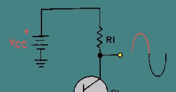
So, we connect an “amplifier” to the sound card through the linear output, and from its outputs, through a resistor with a nominal value of 1 KOHM, a speaker is connected (see photo):
- In order to avoid the influence of third-party objects on the quality of measurements, we hang the speaker in the middle of the room on a chandelier. Next, we launch the LFO “program”, set the frequency to 1000 Hz and set the volume control on the computer to the middle position;
- To avoid signal distortion, connect the multimeter to the amplifier output and, adjusting the volume on it, set the voltage to 20 Volts;
- Connect the multimeter to the speaker;
- We increase the generator frequency (starting from a frequency of 5...10 Hz), monitor the voltmeter data until the desired speaker frequency at maximum voltage (Umax) reaches its maximum, after which it begins to decrease. The generator readings at which Umax reached its maximum on the voltmeter are recorded as Fs data;
- We gradually increase the frequency relative to Fs until the readings stop changing. We write down the value of Umin (a further increase in frequency, of course, will cause an increase in amplitude, but this data is no longer important to us);
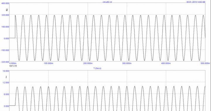
We can already express the obtained data in the form of a graph of the amplitude-frequency characteristics of the speaker:
When viewing the graph, you can observe new input Uav, F1 and F2, these are the frequencies with which we will determine the quality factor of the speaker using the formulas Qes, Qts, Qms and Uav.
Previously, calculations were done manually, but now everything is extremely simple - download the TSCalc program, insert known values and get the result:
- Value Rmax=Umax*1000;
- Re value = speaker DC resistance value;
- Substituting these values into the program we get Rx;
- Uav = Rx/1000
- We look for F1 by decreasing the frequency down relative to Fs until the voltmeter shows the value Uav;
- We look for F2 in the same way, only we raise the frequency up;
- Substituting the obtained values of F1, F2 and Fs, we obtain the required data on the quality factor of the resonant frequencies.
- Next, we need to find the resonant frequency of the speaker in a closed space - Fc. To do this, we fix the speaker with the magnet outward (not important, it’s just more convenient) in a pre-prepared box, and look for what we are looking for, similar to the Fs value.
- Substituting the values of the box volume already known to us, as well as the found data Fc and Fs, we obtain the values of the equivalent volume – Vas;
- We find the effective diameter and maximum displacement of the diffuser using a ruler.
Drawer selection
Now that we know all the necessary parameters, we can begin to select the type of subwoofer enclosure.
Attention! No matter how much I would like to upset you, only the parameters obtained (and not your desires) are the main factors determining the type of case. This does not mean that you will not be able to assemble the type of enclosure you have chosen, but whether it will produce the sound we need is the question...
Free air (free emitter)
This type of speaker is suitable when Fs > 100 Hz. As you might guess, it will not make a traveling subwoofer, since it has almost completely no low-frequency range.
The maximum where it can be identified is the rear of the car, but the best option would be to look for another speaker.
Closed Box
We choose this type if the Qts value is less than 0.8-1.0 (optimally 0.7), and Fs/Qts is equal to 50. It is not at all difficult to calculate.
Vented Box (bass reflex)
Optimal for Qts less than 0.6 (optimal indicator 0.39), and Fs/Qts equal to 85. More difficult to design.
Band Pass
It has the greatest efficiency, and at the same time is the most difficult to manufacture. Optimal with Fs/Qts value equal to 105.
PassiveRadiator (passive radiator)
The same bass reflex, only a membrane emitter is installed in place of the pipe. The calculation of its parameters is similar to a bass reflex, but manufacturing is a little more complicated.
Although if you take an old speaker, remove the magnet, diffuser and basket from its body, glue a plexiglass plate (getinax, etc.) to the rubber ring, and screw a weight (bolt and nut) into the center of it, with which you can adjust Fc, then You will get a very good and not expensive PassiveRadiator.
Any of the presented options can be made with either one or two speakers. So, we know the parameters, we have decided on the type of housing, it’s time to start calculating the housing.
Box calculation
In this case, I decided to use the JBLSpeakerShop program.
Don’t expect details from me, this “program” is very simple and understandable (by the way, video instructions on the Internet are always at your service).
But I’ll still tell you the procedure:
- Download the program and run it through the “setup.exe” file located in the first disk, after which we indicate the path to the second part of the installation file;
- We launch the program and go to the “Loadspeaker” menu where we enter the head parameters;
- We select the type of box and go to “Box - Parameters”, where in the selected option we enter the frequency and volume of the desired resonance (when entering these parameters, you can improvise and observe the result on the graphs);
- Next, after the parameters have been selected, if your subwoofer has a bass reflex, activate the “Vent” key and enter the pipe parameters;
- In the “Dimensions” submenu, select the shape and dimensions of the box;
- In the “Graphs” menu, select the displayed graph;
- Print the result - “Ctrl + P”.
Making a subwoofer box
Preparation
As you know, practice is the criterion of truth, but since the calculation is completed, we proceed to the most interesting part of our instructions, where one rule reigns - measure seven times, cut once.
Advice! When choosing a housing material, it is necessary to take into account that the greater the power of the speaker, the thicker its wall should be, and the stiffer the fastenings.
So:
- We take a prepared sheet of high-quality (not dried or old) plywood, which is an order of magnitude stronger than chipboard, and draw all sides of the box on it.
- There is no point in saving at this stage - then there will be nothing to correct the mistakes.
- If you have a “manual drive” hacksaw, then it is better to choose one with small teeth and a guide. To avoid delamination and cracks, you should cut slowly, at an angle; the above is also true when working with an electric jigsaw.
- Using a file, we process all the protruding fragments of plywood and compare the humps and depressions resulting from sawing.
- We measure out the blocks and saw them to size, for which we will “estimate” the body from the sawn parts and take measurements.
One of the critical moments is making a hole for the speaker.
Since it’s somehow problematic to find a drill with a diameter of 150...300 millimeters, we’ll think with our heads:
- We measure the diffuser with a rubber clip and, taking a slightly larger value, use a compass to measure a circle on the plywood. Next, we step back from this line inward by the radius of the selected drill (adding a couple more millimeters) and mark a circle of smaller diameter.
Method one
Using a drill, drill 10…15 millimeters into the line of the small circle, insert a jigsaw file into the resulting hole and cut out the hole, running the saw in a large circle.
Advice! Before starting drilling, place the plywood on some hard surface - this way, at the exit, the drill will not “tear” the back wall.
Method two
It is not necessary to draw the second circle - we drill a hole anywhere inside the circle, insert a jigsaw file and smoothly bring it to the line of the drawn circle.
Method three
We drill holes close to each other along the entire diameter of the small circle, then punch the jumpers between them and process the circle with a file.
Estimate the speaker according to the hole, and if everything suits you, drill holes for mounting nuts, which can be purchased at any furniture fittings department.
Advice! The connectors used in concert acoustics are very practical and reliable; it is best to use them.
Box assembly
So, the holes for the speaker and bass reflex are made, the bars are sawed, we move on to assembly work:
- We take a drill with a diameter two times smaller than the diameter of the self-tapping screw and drill through the sheets of plywood in those places where they will join the bars and other walls;
- Before joining the parts, coat with a thick layer the places where the walls and bars come into contact. A thick layer of glue in our case performs two functions simultaneously - it increases the strength of the structure and seals the joints;
Advice! Screw the back wall at the last assembly stage.
- We install the speaker, and coat the junction of the diffuser and plywood with automotive, water-repellent sealant (good seam sealing + can be easily removed if necessary);
- We make a bass reflex from available round-shaped materials (except for metal pipes, pieces of water supply and sewerage) by entering the diameter of the pipe into the program and obtaining the value of its length. It’s not worth fixing it tightly yet; we’ll still have to configure it.
By the way, the bass reflex can be square in shape, in which case you will have to use your imagination a little during its manufacture:
Any noise-absorbing material can be used as a damping material, for example a thick layer of vorsonite, felt, cotton wool, hard foam rubber, etc.
- During setup, replace the back cover of the box;
- We connect the unit through an amplifier to a low-frequency generator, and a voltmeter to the speaker contacts;
- By changing the frequency of the generator, using the method described above, we find the value of Fc;
- If the desired value differs from the calculated one, then by changing the parameters of the bass reflex and the amount of damping material inside the subwoofer box, we experimentally find exactly the moment when the resonant frequency will completely suit us.
- If the estimated length of the bass reflex pipe exceeds the length of the subwoofer itself, its diameter should be changed;
- We complete the assembly work by fastening all the remaining parts tightly.
This concludes the instructions for making a car subwoofer with your own hands. All you have to do is check your work in action.
We turn on the hardest version of the musical composition at full volume and listen to what is being reproduced for the appearance of extraneous noise, rustling, or whistling:
- The whistle indicates a gap remaining inside the unclosed space, a hole that should be covered with sealant, putty or glue;
- The rustling sound means that the speaker's moving damper is in contact with its cone.
We finish the external processing of the subwoofer: we round off the sharp corners, sand them, cover the holes and cracks with putty or mastic, then glue them with material and install decorative grilles on the speaker diffuser and the bass reflex pipe.
That's all. I hope you will be pleased not only with the price of your “brainchild,” but also with the excellent quality of its sound.
After all, if you did everything right, then without your prompting hardly anyone would guess that the powerful and clear bass coming from the inside of your car is being reproduced from a homemade subwoofer. Which, by the way, is not a shame to brag about)))
In this article we will look at how to make a subwoofer with your own hands, without delving into the depths of electroacoustics, without resorting to complex calculations and subtle measurements, although you will still have to do some things. “Without any special difficulties” does not mean “slap on a brick, drive away, grandma, mogarych.” These days, it is possible to simulate very complex acoustic systems (AS) on a home computer; See the end for a link to a description of this process. But working with a finished device on a whim gives something that you cannot get by any reading or viewing - an intuitive understanding of the essence of the process. In science and technology, discoveries at the tip of a pen are rarely made; Most often, a researcher, having gained experience, begins to “gut” understand what’s what, and only then looks for mathematics suitable for describing the phenomenon and deriving design engineering formulas. Many great people recalled their first unsuccessful experiences with humor and pleasure. Alexander Bell, for example, initially tried to wind the coils for his first telephone with bare wire: he, a musician by training, simply did not yet know that live wire needed to be insulated. But Bell still invented the telephone.
About computer calculations
Do not think that JBL SpeakerShop or other acoustics calculation program will give you the only possible, most correct option. Computer programs are written using established, proven algorithms, but non-trivial solutions are impossible only in theology. “Everyone knows that you can’t do this. There is a fool who doesn't know this. He is the one who makes the invention."– Thomas Alva Edison.
SpeakerShop appeared not so long ago, this application was developed very thoroughly and the fact that it is used very actively is an absolute plus for both developers and amateurs. But in some ways the current situation with him is similar to the story with the first photoshops. Who else used Windows 3.11, remember? - back then they just went crazy with image processing. And then it turned out that in order to take a good picture, you still need to know how to take photographs.
What is this and why?
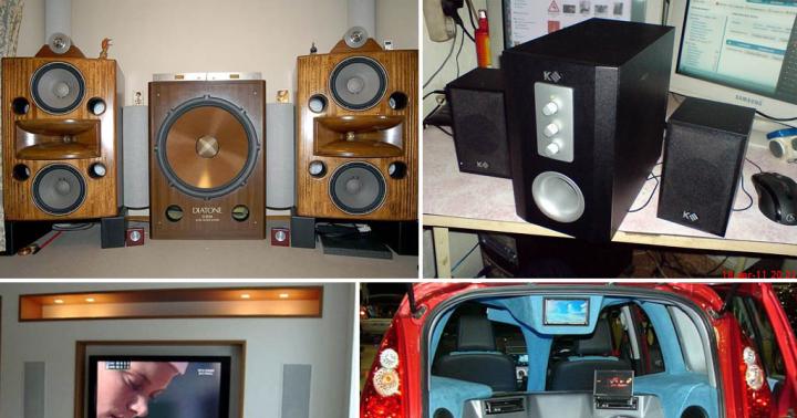
A subwoofer (simply a sub) in its literal translation sounds funny: a burr. In reality, this is a bass (low-frequency, woofer) speaker that reproduces frequencies below approx. 150 Hz, in a special acoustic design, a box (box) of a rather complex device. Subwoofers are also used in everyday life, in high-quality floor-standing speakers and inexpensive desktop ones, built-in and in cars, see fig. If you manage to make a subwoofer that reproduces bass correctly, you can safely take on it, because LF reproduction is perhaps the fattest of the whales on which all electroacoustics stand.

It is much more difficult to make a compact low-frequency section of the speaker system than the mid-range and high-frequency (mid- and high-frequency) parts, firstly, due to an acoustic short circuit, when sound waves from the front and rear radiating surfaces of the speaker (loudspeaker head, GG) cancel each other out: lengths LF waves are meters, and without proper acoustic design of the GG, nothing prevents them from immediately converging in antiphase. Secondly, the spectrum of sound distortion in the low frequencies extends far into the best audible region of the midrange. In essence, any broadband speaker has a low-frequency section into which midrange and high-frequency emitters are built. But from the point of view of ergonomics, an additional requirement is imposed on the subwoofer: a subwoofer for the home should be as compact as possible.
Note: All types of acoustic design of LF GG can be divided into 2 large classes - some dampen the radiation from the rear of the speaker, the second reverse it in phase by 180 degrees (turn the phase) and re-radiate it from the front. A subwoofer, depending on the properties of the GG (see below) and the required type of its amplitude-frequency response (AFC), can be built according to a circuit of one class or another.
People can distinguish the direction of sounds below 150 Hz very poorly, so in an ordinary living room a sub can be placed basically anywhere. MF-HF speakers (satellites) of acoustics with a subwoofer are very compact; their location in the room can be selected optimally for the given room. Modern housing is, to put it mildly, no different in terms of excess space and good acoustics, and it is not always possible to “stuff” at least a couple of good broadband speakers into it correctly. Therefore, making a subwoofer yourself allows you not only to save a very significant amount of money, but also to still get a clear, true sound in this Khrushchev, Brezhnevka or modern new building. A subwoofer is especially effective in full surround sound systems, because... putting 5-7 columns on a full page each is too much even for the most sophisticated users.
Bass
Reproducing bass is not only technically difficult. The generally narrow low-frequency region of the entire spectrum of sound waves is heterogeneous in its psychophysiological effect and is divided into 3 regions. To choose the right bass speaker and make a subwoofer box with your own hands, you need to know their boundaries and meaning:
- Upper bass (UpperBass) – 80-(150…200) Hz.
- Average bass or midbass (MidBass) – 40-80 Hz.
- Deep bass or sub-bass (SubBass) – below 40 Hz.
Top
Middle
For midbass, the main task when creating a subwoofer is to ensure the highest GG output, a given shape of the frequency response and its maximum uniformity (smoothness) in the minimum volume of the box. The frequency response, which is close to rectangular towards lower frequencies, gives a powerful but harsh bass; Frequency response, uniformly falling - clean and transparent, but weaker. The choice of one or the other depends on the nature of what you are listening to: rockers need an “angrier” sound, while classical music needs a gentler sound. In both cases, large dips and spikes in the frequency response spoil the subjective perception with formally identical sound technical parameters.
Depth
Sub-bass has a decisive influence on the timbre (color) of the sound of musical instruments only for wind organs in halls specially built for them. Strong sub-bass components are typical for the sounds of natural and man-made disasters, strong explosions and the voices of certain animal species (lion's roar). Over 90% of people either do not hear sub-bass at all or hear it indistinctly. For example, if the sounds of a tropical hurricane and a nuclear explosion, fundamentally different in nature, are filtered out from everything except sub-bass, then hardly anyone can tell what is really going on there. Therefore, a home subwoofer is almost always optimized for midbass, and the remainder of the subbass, whatever happens, masks the room’s own noise. Which, by the way, is very suitable for and why it is very useful.Sub-bass in the car
The noise masking effect is especially necessary in a cramped and noisy car interior, so car subwoofers are optimized for sub-bass. Sometimes, for the sake of this, Hi-Fi lovers at high speed give the entire trunk to the subwoofer, placing 15”-18” monster speakers there with 150-250 W of peak power, see fig. However, a quite decent subwoofer can be made for a car without sacrificing useful volume in the body, see below.

Note: The peak power of a speaker is often equated with noise, which is incorrect. At peak power the sound is distorted, but still intelligible, i.e. distinguishable by meaning. Noise power is defined as that at which a speaker can operate for a certain period of time (usually 20 minutes) without burning out or suffering mechanical damage. The sound in this case is most often an incoherent wheezing, which is why such power is called noise. But in some types of acoustic design, the noise power of the speaker may be lower than the peak, see below.
What kind of speaker do you need?
A complete calculation of acoustic design is carried out according to the so-called. Thiel-Small parameters (TSP). Since we decided to spend time and labor on setting up the sub, we will only need the full quality factor of the head at its own resonant frequency Qts, because It is based on this that the optimal acoustic design option is selected. Depending on the Qts value, speakers are divided into 4 groups:
- Qts<0,5 – «безразличные» сверхнизкодобротные. Очень дорогие, очень низкая отдача, но способны воспроизводить подбасы вплоть до 20-15 Гц. Настройка сабвуфера с такими без звукомерной камеры и специальной измерительной техники невозможна, т.к. резонансный пик не выражен.
- 0,5
- 0,7
- Qts>1 – high-quality. High output, low price, harsh sound in suboptimal design. It is difficult to obtain a smooth frequency response. Compact, available in diameters (smaller) up to 6” (155 mm). Optimal for a desktop subwoofer or for a TV (not for a home theater!).
- 0,7
Measurements
In the manufacturer's specifications for speakers, Qts may be designated as Qп or simply Q, but it is not always present there, and public databases like WinISD are full of errors. Therefore, we will most likely have to determine the Qts value at home.
Preparation
First of all, we select and prepare a room for acoustic measurements. It should have as many curtains, curtains, carpets on the floor and walls, and upholstered furniture as possible. Hard horizontal surfaces (tables) need to be covered with something fluffy; It wouldn’t hurt to throw more pillows everywhere. Corners distort the sound field especially strongly, incl. hard furniture with walls, they need to be curtained with something, for example, clothes on hangers. Next, we connect long wires to the speaker and hang them in the geometric center of the ceiling (under the chandelier, if there is one) with the front side of the diffuser down at a height from the floor of 2/3 of the ceiling height.

Now you need to assemble a measurement diagram, as shown at the top in Fig. We will still need the lower circuit to measure the impedance (impedance) of speaker Z. This one differs from the measuring circuit without a transformer usually used by amateurs in quite professional accuracy: in conventional circuits, approx. 1.5 V even with an input resistance of the tester of 10 MOhm. The operation of this circuit is based on the fact that the impedance of the transformer and R2, on the one hand, is much greater than the impedance of the main generator; on the other hand, it is much less than the output impedance of an audio frequency power amplifier, and on the fact that the lousiest digital multitester at a limit of 200 mV has an input impedance of more than 1 MOhm. However, if the measurement signal is supplied from an audio frequency generator (AFG) with a standard 600-ohm output, this circuit is not suitable for measuring Z.
Procedure
From a computer with a GZH emulation program, the measuring signal is supplied from the output of the sound card. You need to “drive” it within the range of 20-100 Hz at first with a discrete (step) of 10 Hz. If the GG resonance is not visible, it is unsuitable for a subwoofer. Or the seller shamelessly deceived you by selling you for 100 rubles. indifferent GG priced from $200.

When the boundaries of the resonant peak are determined, we “pass” it with a discrete of 1 Hz and build the frequency response. If the high- or medium-quality GG is closer to the upper limit of Qts, you will get a graph similar to the one in pos. I fig. In this case:
- According to formula (1) to pos. II find U(F1,F2);
- According to the graph we find F1 and F2;
- Using formula (2), we check whether the calculated natural resonance frequency in free space F’s coincides with the measured Fs. If the discrepancy is more than 2-3 Hz, see below;
- Using formula (3) we find the mechanical quality factor Qms, then using formula (4) the electrical quality factor Qes and, finally, using formula (5) the required total quality factor Qts.
If the quality factor of the GG is closer to low or such, which is generally good, the resonance curve will be noticeably asymmetrical, and its peak will be flat, blurred, pos. III, or the test using formula (2) will not converge even with repeated measurements. In this case, from the graph we determine the points of greatest inclination of the tangents to the concave “wings” of the peak A1 and A2; mathematically, in them the second derivative of the function describing the resonance curve reaches a maximum. For Umax then we take, as before, its value at the top of the peak, and for Umin - calculated from the f-le at pos. III new value U(F1,F2).
System structure
Have you tried it on? Is the speaker suitable? Take your time to choose a design. First you need to choose a block diagram of the entire sound system, because its electronic part may account for as much of the cost as a good bass speaker. A sound system with a subwoofer can be built according to one of the following. diagrams, see fig.

Note: The equalizer and infra-low-pass filter FINCH (rumble filter) in all circuits are turned on before the inputs of stereo channels.
Pos. 1 – system with passive power filtering. Plus – you don’t need a separate bass amplifier; it connects to any UMZCH. Huge disadvantages, first, mutual electrical leakage of channels in the subwoofer along the midrange: for LC filters that reduce it to an acceptable value, you will need a decent case, which in order to purchase their components will first have to be filled by about a third with money (in 100 ruble bills). Secondly, the output resistances of the low-pass filters of the low-pass filter together with the input GG of the speaker form a tee, and each channel of the UMZCH will theoretically spend a quarter of the power on warming its neighbor with its low-pass filter. In reality – more, because on power and losses in filters are significant. However, the power-filtering system is applicable in low-power subwoofers with independent sound emitters, see below.
Pos. 2 – passive filtering to a separate bass UMZCH. There are no power losses, the mutual influence of channels is weaker, because The characteristic resistances of the filters are kilo-ohms and tens of kilo-ohms. Currently, it is practically not used, because Assembling an active filter on microcircuits turns out to be much simpler and cheaper than winding passive coils.
Pos. 3 – active analog filtering. The channel signals are added by a simple resistor adder, sent to an analog active low-pass filter, and from it to the bass UMZF. The interference of channels is negligible and unnoticeable under normal listening conditions, and the costs for components are low. The optimal circuit for a homemade subwoofer for a novice amateur.
Pos. 4 – full digital filtering. Channel signals are fed to a splitter P, which divides each of them into at least 2 equal to the original one. One signal from the pair is fed to the MF-HF UMZF (possibly directly, without a high-pass filter), and the rest are combined in adder C. The fact is that with resistor addition at the lower frequencies of the midbass and sub-bass, electrical interaction of signals in the low-pass filter is possible, several distorting the total bass. In the adder, the signals are added digitally or analoguely, eliminating their mutual influence.
From the adder, the common signal is fed to a digital low-pass filter with built-in analog-to-digital (ADC) and digital-to-analog (DAC) converters, and from it to the bass UMZCH. The sound quality and channel isolation are the highest possible today. The costs of microcircuits for this entire enterprise turn out to be feasible, but working with ICs requires some amateur radio experience, and even more if you do not buy a ready-made set (which is significantly more expensive), but select the system components yourself.
Decor
In Fig. The most common acoustic design schemes for home subwoofers are given. Labyrinths, horns, etc. do not meet the requirements of compactness. Schemes that are preferable for beginners are highlighted in green, schemes that are feasible for them are highlighted in yellow, and unsuitable ones are highlighted in red. Those with more experience may be surprised: is the 6th bandpass for dummies? No problem, this great bass tube speaker can be set up in a weekend. If you know how.

Shield
Designing a subwoofer in the form of an acoustic screen (shield, item 1) at home is feasible if the GGs are built into the wall cladding, because their sizes are comparable to the lengths of sub-bass waves. Hence the advantage - there are no problems with sub-bass, as long as the speakers can handle it. Another thing is that it is extremely compact; the sub does not take up any useful space at all. But there are also serious disadvantages. The first is a large amount of construction work. Secondly, the acoustic screen does not affect the frequency response of the GG in any way. “Humpbacked” will sing just like that, so you can only install expensive, low-quality and indifferent speakers on the shield. The downside, so to speak, is that their recoil is small and the shield is in no way capable of increasing it.
Closed box
The biggest plus of a closed box (item 2) is deep damping of the GG; for inexpensive, high-output, high-quality speakers, this is the only acceptable type of acoustic design. But this plus also entails a minus: with deep damping, the noise power of the GG is often lower than the peak, especially for expensive powerful heads. The coil is already smoking, but no wheezing can be heard. An overload indicator is needed, but the simplest ones without a separate power supply distort the signal.
An equally big plus is the extremely smooth, smoothly falling frequency response and, as a result, the purest and most vibrant sound. For this reason, high-quality powerful high-quality generators are produced specifically for installation in closed boxes or 4th order bandpasses (see below).
Minus - of all speakers of equal volume, a closed box has the highest lowest reproducible frequency, because it increases the resonant frequency of the speaker and is not able to increase its output at frequencies below it. Those. In terms of compactness, a subwoofer in a closed box is a stretch. This drawback can be reduced to some extent by filling the box with synthetic padding: it perfectly absorbs the energy of sound waves. The thermodynamic process in the box then goes from adiabatic to isothermal, which is equivalent to an increase in its volume by 1.4 times.
Another significant disadvantage is that you can only make a passive subwoofer in a closed box, because The electronics in it get very hot even when placed in a fenced off compartment. If you come across old 10MAS-1M speakers, run them at half power for half an hour and touch the body with your hand - it will be warm.
FI
Note: a passive radiator (PI) is equivalent in all respects - instead of a pipe with a port, a bass speaker is installed without a magnetic system and with a weight instead of a coil. There are no “tuning-free” methods for calculating PI, which is why PI is a rare exception in industrial production. If you have a burnt-out bass speaker lying around, you can experiment - the adjustment is made by changing the weight of the load. But keep in mind that it is better not to make an active PI for the same reason as a closed box.
About deep crevices
Acoustics with deep slots (items 4, 6, 8-10) are sometimes identified with FI, sometimes with a labyrinth, but in fact this is an independent type of acoustic design. There are many advantages to a deep slit:
The deep slot has only one drawback, and only for beginners: it is not adjustable after assembly. As it is done, so it will sing.
About anti-acoustics

Bandpasses
BandPass means band pass, which is the name given to speakers without direct radiation of sound into space. This means that bandpass speakers do not emit midrange due to its internal acoustic filtering: the speaker is placed in a partition between resonating cavities that communicate with the atmosphere through pipe ports or deep slots. Bandpass is an acoustic design specific to subwoofers and is not used for completely separate speakers.
Bandpasses are divided by order of magnitude, and the order of a bandpass is equal to the number of its own resonant frequencies. High-quality GGs are placed in 4th-order bandpasses, where it is easy to organize acoustic damping (position 5); low- and medium-quality - in 6th order bandpasses. Contrary to popular belief, there is no noticeable difference in sound quality between the two: already at the 4th order the frequency response at low frequencies is smoothed to 2 dB or less. The difference between them for an amateur is mainly in the difficulty of setting: in order to accurately adjust the 4th bandpass (see below), you will have to move the partition. As for 8th order bandpasses, they obtain 2 more resonant frequencies due to the acoustic interaction of the same 2 resonators. Therefore, 8th bandpasses are sometimes called 6th order class B bandpasses.
Note: idealized frequency response at low frequencies for some types of acoustic design are shown in Fig. red. The green dotted line shows the ideal frequency response from the point of view of the psychophysiology of hearing. It can be seen that there is still enough work in electroacoustics.

Amplitude-frequency characteristics of the same loudspeaker head in different acoustic designs
Car subwoofers
Car subwoofers are usually placed either in the cargo compartment, or under the driver’s seat, or behind the back of the rear seat, pos. 1-3 in Fig. In the first case, the box takes up useful volume, in the second, the sub works in difficult conditions and can be damaged by feet, in the third, not every passenger will be able to tolerate powerful bass right next to their ears.

Recently, car subwoofers are increasingly being made of the stealth type, built into the rear fender niche, pos. 4 and 5. Sufficient sub-bass power is achieved by using special auto speakers with a diameter of 12” with a rigid diffuser, which is little susceptible to the membrane effect, pos. 5. How to make a subwoofer for a car by molding a wing niche, see next. video.
Video: DIY car subwoofer “stealth”
It couldn't be simpler
A very simple subwoofer that does not require a separate bass amplifier can be made using a circuit with independent sound emitters (IS), see fig. In fact, these are two channel LF GGs placed in a common long housing installed horizontally. If the length of the box is comparable to the distance between the satellites or the width of the TV screen, the “blurring” of the stereo is hardly noticeable. If listening is accompanied by viewing, it is completely unnoticeable due to involuntary visual correction of the localization of sound sources.

Using the scheme with independent FMs, you can make an excellent subwoofer for a computer: a box with speakers is placed in the far upper corner under the tabletop. The cavity underneath is a resonator tuned to a very low frequency, and an unexpectedly good sub-bass comes out from the small box.
FI for a subwoofer with independent FIs can be calculated in the speaker shop. In this case, the equivalent volume Vts is taken twice as large as measured, the resonant frequency Fs is 1.4 times lower, and the total quality factor Qts is 1.4 times higher. The material of the box, as elsewhere below, is MDF from 18 mm; for subwoofer power from 50 W – from 24 mm. But it is better to place the speakers in a closed box; in this case, it can be done without calculation: the length inside is taken at the installation site, ranging from 0.5 m (for a computer) to 1.5 m (for a large TV). The internal cross-section of the box is determined based on the diameter of the speaker cone:
- 6” (155 mm) – 200x200 mm.
- 8” (205 mm) – 250x250 mm.
- 10” (255 mm) – 300x300 mm.
- 12” (305 mm) – 350x350 mm.
In the worst case (an under-table computer sub with 6” speakers), the volume of the box will be 20 liters, and the equivalent with filling will be 33-34 liters. With a UMZCH power of up to 25-30 W per channel, this is enough to get decent midbass.
Filters
In this case, it is better to use LC filters of type K. They require more coils, but in amateur conditions this is not essential. K-filters have low attenuation in the stopband, 6 dB/oct per link or 3 dB/oct per half-link, but have an absolutely linear phase response. In addition, when operating from a voltage source (which, with great accuracy, is the UMZCH), the K-filter is little sensitive to changes in load impedance.
At pos. 1 pic. Diagrams of K-filter sections and calculation formulas for them are given. R for the low-frequency GG is taken equal to its impedance Z at the low-pass filter cutoff frequency of 150 Hz, and for the high-pass filter equal to the satellite impedance z at the high-pass filter cutoff frequency of 185 Hz (formula in position 6). Z and z are determined according to the diagram and formula in Fig. above (with measurement diagrams). Working diagrams of filters are given in pos. 2. If you prefer to buy additional capacitors rather than wind coils, exactly the same parameters can be made from P-links and half-links.

Data and circuits for making filters for a simple subwoofer with independent emitters
The attenuation of the low-pass filter in the stopband is 18 dB/oct, and the attenuation of the high-pass filter is 24 dB/oct. This frankly non-trivial ratio is justified by the fact that the satellites are unloaded from the low frequencies and give a cleaner sound, and the remainder of the low frequencies reflected from the high-pass filter is sent to the low-frequency speakers and makes the bass deeper.
Data for calculating filter coils are given at pos. 3. They need to be positioned mutually perpendicular because K-filters operate without magnetic coupling between the coils. When calculating, the dimensions of the coil are specified and the number of turns is determined using the inductance found in the order of calculating the filter. Then, using the laying coefficient, the diameter of the wire in the insulation is found; it should be at least 0.7 mm. It turns out less - increase the size of the coil and recalculate.
Settings
Setting up this subwoofer comes down to equalizing the volumes of the bass and satellite speakers, respectively. cutoff frequencies. To do this, first prepare the room for acoustic measurements, as described above, and a tester with a bridge and transformer. Next you will need a condenser microphone. For a computer one, you will have to make some kind of microphone amplifier (MCA) with bias applied to the capsule, because a regular sound card cannot simultaneously receive a signal and emulate a frequency generator, pos. 4. If you can find a condenser microphone with a built-in MUS, even an old MKE-101, great, its output is connected directly to the primary (smaller) winding of the transformer. The measurement procedure is simple:
- The microphone is fixed opposite the geometric center of the satellites at a horizontal distance of 1-1.5 m.
- Disconnect the subwoofer from the UMZCH and apply a 185 Hz signal.
- Record the voltmeter readings.
- Without changing anything in the room, they turn off the satellites and connect the sub.
- A 150 Hz signal is supplied to the UMZCH and the tester readings are recorded.
Now you need to calculate the equalizing resistors. The volumes are equalized by muting the louder links in a series-parallel circuit (item 5), because it is necessary to keep the previously found values of Z and z unchanged modulo. Calculation formulas for resistors are given in pos. 6. Power Rg – not less than 0.03 of the power of the UMZCH; Rd – any from 0.5 W.
It's also simple
Another option for a simple, but real subwoofer is with a paired low-frequency generator. Pairing woofers is a very effective way to enhance their sound quality. The design of a subwoofer based on a pair of old 10GD-30 is shown in Fig. below.

The design is very perfect, 6th order bandpass. Bass amplifier - TDA1562. You can also use other high-quality GGs with a relatively small diffuser stroke, then you may have to make adjustments by selecting the length of the pipes. It is produced at control frequencies of 63 and 100 Hz. way (control frequencies are not resonant of the acoustic system!):
- Prepare the room, microphone and equipment as described above.
- 63 and 100 Hz are supplied to the UMZCH alternately.
- Change the lengths of the pipes, achieving a difference in voltmeter readings of no more than 3 dB (1.4 times). For gourmets - no more than 2 dB (1.26 times).
The tuning of the resonators is interdependent, so the pipes need to be moved according to: pulled out the short one, pushed the long one in by the same amount, in proportion to its original length. Otherwise, you can completely upset the system: the peak of the optimal setting at the 6th bandpass is very sharp.
- A dip between 63 and 100 Hz – the partition needs to be moved towards the larger resonator.
- Dips on both sides of 100 Hz - the partition is shifted towards the smaller resonator.
- The burst is closer to 63 Hz - you need to increase the diameter of the long pipe by 5-10%
- A burst closer to 100 Hz is the same, but for a short pipe.
After any of the adjustment procedures, the subwoofer is reconfigured. For its convenience, complete assembly with glue is not done at first: the partition is tightly smeared with plasticine, and one of the side walls is placed on double-sided tape. Make sure there are no gaps!

Pipes for resonators
Ready-made elbow pipes for acoustics are sold in music and radio stores. You can make a telescopic acoustic pipe with your own hands from scraps of plastic or cardboard pipes. In both cases, across the inner mouth, you need to firmly glue 2 pieces of fishing line: one with tension, the other with a loop protruding outward, see fig. on right. If the pipe needs to be moved apart, press on the tight line with a pencil, etc. If you shorten it, pull the loop. Tuning a resonator with a pipe is thus speeded up many times.
Powerful 6th order
Drawings of the 6th order bandpass for 12” GG are given in Fig. This is already a solid floor-standing design with a power of up to 100 W. It is configured like the previous one.

Drawings of a 6th order bandpass subwoofer for a 12″ speaker
4th order
Suddenly you have a 12” high-quality GG at your disposal; on it you can make a 4th order bandpass of the same quality, but more compact, see fig; dimensions in cm. However, setting it up will be much more difficult, because Instead of manipulating the pipe of a larger resonator, you will have to immediately move the partition.

6th order bandpass subwoofer for 12″ speaker
Electronics
The bass UMZF for a subwoofer is subject to the same requirement as filters, the requirement of complete linearity of the phase response. It is satisfied by UMZCHs made using a bridge circuit, which also reduces the nonlinear distortions of integral UMZCHs with a non-complementary output by an order of magnitude. UMZCH for a subwoofer with a power of up to 30 W can be assembled according to the diagram in pos. 1 rice; 60-watt according to the circuit on pos. 2. It is convenient to make an active subwoofer on a single chip of a 4-channel UMZCH TDA7385: a couple of channels are sent to the satellites, and the other two are connected via a bridge circuit to the sub, or, if it has independent amplifiers, they are sent to the woofers. The TDA7385 is also convenient because all 4 channels have common inputs for the St-By and Mute functions.

According to the diagram at pos. 3 makes a good active filter for a subwoofer. The gain of its normalizing amplifier is regulated by a variable resistor of 100 kOhm over a wide range, so in most cases the rather tedious procedure of equalizing the volumes of the subwoofer and satellites is eliminated. Satellites in this version are switched on without a high-pass filter, and volume preset potentiometers with slots for a screwdriver are built into the mid-high frequency amplifiers.
You may want to design a slot sub from scratch rather than mess around with reconfiguring prototype subwoofers to fit your speaker. In this case, follow the link: //cxem.net/sound/dinamics/dinamic98.php. The author, we must give him his due, was able to explain at a “for dummies” level how to calculate and make a high-quality subwoofer using modern software. However, in a big deal there are some mistakes, so when studying the source, keep in mind:

And still…
Making a subwoofer yourself is a fascinating task, useful for the development of intelligence and skill, and besides, a good bass speaker costs one and a half times less than a pair of a lower class. However, during control auditions, both seasoned experts and casual listeners “from the street”, all other things being equal, clearly prefer sound systems with full channel separation. So first think about it: won’t you still have to deal with a couple of separate columns on your hands and your wallet?
The thought of assembling a subwoofer with my own hands has been haunting me for several months now. And then one day, when I went to the Radio Shop, a Semtoni woofer caught my eye, and I decided to buy it...
I spent the next week doing calculations. I downloaded several programs for calculating subwoofer enclosures (DLSBox2000, JBL-Speakershop, WinISD...) I liked the DLSBox2000 program most of all. With her help I did the calculations. And this is what happened - the efficiency of this design (FI) for my speaker is 76%, volume - 37 lire (external dimensions 45x35x35cm), bass reflex 75x100mm. (diameter/length).
Then I drew a sketch on paper and began making it.

I screwed all the walls together with 50mm long screws. All connections are made with PVA glue (advice - don’t skimp on the glue, the excess will squeeze out). Inside, for greater reliability, I coated the seams with silicone sealant. In principle, this is not necessary, but it’s better to miss and forget than to take it apart again later.


Next I started puttingty on the subwoofer body. I used two-component automotive putty (you can make putty yourself by mixing small sawdust and PVA glue, as an option). Once the putty was dry, I sanded the body until it was almost perfectly flat.


Then I cut out holes for the bass reflex, socket, and pocket handles.


I assembled the subwoofer body to see how it sounds.

All my doubts about the correct calculation of the volume of the subwoofer were instantly dispelled - a soft, even bass was playing. Having made sure that nothing was whistling anywhere, I removed the “accessories” and began to cover the case with self-adhesive paper with a leather texture. Collected.


What was needed to make a homemade subwoofer:
- Semtoni woofer 10”(25 cm) 350w(rms, max) - 1100 rubles.
- Chipboard 20mm. - free, found in the attic
- PVA glue - free, already in stock
- Self-tapping screws 50mm. 100 pieces. - 26 rubles
- Silicone sealant, transparent - 59 rubles
- Sealant gun - 40 rubles
- Socket with terminals - 65 rubles
- Speaker wire 1m. - 60 rubles
- Bass reflex 75x100mm. - 40 rubles
- Handles “Pockets” 2 pcs. - 100 rubles
Total about 1800 rubles.
DIY 60W sound amplifier
While there is some time, another brand new circuit appears on the site, we all know that the greater the power of the amplifier, the more expensive it is. But what can you do if you need an amplifier that is both powerful and at the same time not too expensive? I would like to present to many a familiar circuit of a 25 or 60 watt permanent amplifier, the cost of which is pennies. As already mentioned, the power of the amplifier depends on the supply voltage and resistor values (60-watt values are indicated in parentheses). The UMZCH was assembled by me and tested many times in operation; it showed very high reliability.
A 60 watt version was assembled.
Sound amplifier on tda 2003 chip
Sound amplifier on tda 2003 chip

There are many schemes on the Internet on the topic of UZCH, which may include scheme how powerful sound amplifiers and average ones. I also wanted something louder and of better quality. And after thinking I decided that it would do 10-20 watt amplifier. I think this is quite enough.
The design was intended for listening to music while playing on a school football field. This output power was just right to allow the music to be heard clearly in all parts of the field. Even a beginner can assemble this circuit, but an experienced radio amateur will sometimes want to treat himself to such an excellent repetition. The circuit is quite easy and stable in operation.
DIY subwoofer amplifier
DIY subwoofer amplifier

The amplifier has protection against overheating, overload and smooth switching, eliminating popping noises in the speakers when the power is turned on.
Unfortunately, there is no printed circuit board left for this amplifier.
But for those who have seriously decided to start assembling it, it will not be difficult.
The output power of this amplifier is 100W
Amplifier circuit for subwoofer
Amplifier circuit for subwoofer
 They often search on the Internet subwoofer circuits,for queries such as LF circuit, or amplifier circuit for active subwoofer.
But there is no pure bass amplifier, take an ordinary amplifier, even for example the circuit of which I give here, you can even use the ones that are on our website, for example, an excellent circuit that has been tried and is called as Ageev amplifier
Just to display sound to a subwoofer with low frequencies, placed in front of the audio channel input Low pass filter.For now, let's get down to our scheme.
Amplifier circuit for speaker on K174UN14
Amplifier circuit for speaker on K174UN14
 With your own hands we will look at it in the article diagram how to create amplifier on k174un14 sound frequency.
The output power of the amplifier is from 5W, but in some cases they write 8W, but do not forget that sound distortion always happens, especially in simple circuits.
Tube amplifier circuit with photo
DIY tube amplifier
 Amplifier assembled on famous lampsOh
6N6P in driver and 2 x 6P14P in parallel in output m cascade.
Amplifier assembled on famous lampsOh
6N6P in driver and 2 x 6P14P in parallel in output m cascade.
A true music lover does not like to listen to music through standard computer speakers. A good speaker system is chosen based on personal preferences. Such a pleasure is not cheap; in addition, sometimes difficulties arise with selecting speakers with the required parameters. In this case, you can make a speaker system with your own hands. In our article we will look at how to make a subwoofer from a regular speaker.
Subwoofer is derived from two words - SUB and WOOFER, which is the literal translation of “subwoofer” and means an acoustic system capable of reproducing sounds at low frequencies, for example from 20 to 100 Hz. Many users prefer to call it a “bass speaker”.
Subwoofers are divided into two types:
- Active subwoofer - the speaker housing contains an amplifier and power supply.
- Passive subwoofer - it does not have an external amplifier.
Choosing a speaker In order to choose a speaker, you need to decide on the dimensions. The following models are available on the modern market:
- Speakers with a 6-inch subwoofer typically provide an additional source of mid-bass. The use of such speakers in terms of sound depth creates a rather modest device that is suitable for a small salon with an average sound system.
- Speakers using an 8-inch subwoofer are used for additional front-facing bass.
- The ideal speakers for a subwoofer in a car are speakers of 10 inches or more. They really have high-quality sound and fill the space with a powerful and pleasant vibration of sound. The speakers are placed in a closed compact housing or the so-called “closed box”, which is capable of providing good sound pressure. The best option for the car is a 12-inch speaker, which can be used in a box with a volume of up to 35 liters.
- 15-inch speakers are a viable option for large car interiors. In this case, a box for a speaker of this diameter should be about 90 liters and occupy the entire luggage compartment. In addition, with such dynamics, you can become slightly deaf, so this option is unlikely to be implemented.
Important! It is necessary to determine the resistance, since a load of 1-2 ohms will greatly spoil the sound. The optimal impedance for a subwoofer speaker is 2 to 4 ohms.
The power of the speakers is definitely a difficult decision to make. There is only one rule, which is that the power of the speaker should be greater than the power of the amplifier. No speaker can function at maximum power for long, so it must have a “safety margin”.
Important! Users do not always have enough sound coming from a home theater. This problem is easily solved with the help of additional speakers.
If you already have both a speaker and an amplifier, then you need to determine this difference and mark the maximum allowable volume for the subwoofer on the amplifier controls. No speaker can maintain sound quality at maximum volume.
Important! After some time (sometimes this situation can happen right away), the disturbed balance will begin to terribly hurt the ears.

How to make a subwoofer for a computer?
Self-manufacturing of a subwoofer is carried out in several stages:
- selection of materials;
- body design;
- subwoofer assembly.
Selection of materials
How to make a subwoofer at home? When starting all work, you should select the necessary materials for making the case. In order to make a subwoofer with your own hands, you need to purchase in advance:
- speaker - selected based on your needs;
- plugs - help connect the speaker to the player; they must perfectly match the connectors of your device;
- wires - used to connect the subwoofer;
- plywood with a multilayer base;
- trimmings of plumbing pipe;
- wood screws, which can be from the smallest to 50 mm in length; wooden blocks having different sections, which can be from 20x20 mm or more;
- silicone sealant; hard foam rubber or felt;
- PVA glue;
- dye.
Having prepared the necessary materials, you should collect the required tools:
- a hacksaw for wood, which would have fine teeth;
- chisel;
- electric drill;
- file;
- jigsaw;
- compass;
- a simple pencil;
- iron ruler;
- screwdriver;
- screwdriver;
- sandpaper - from coarse to “zero”.
Designing the enclosure We begin to design the enclosure of the future subwoofer. To do this, we use a computer and a speaker, which serves as the “heart” of the subwoofer.
Important! In this case, it is very important to have data on all the technical characteristics of the speaker. These include total quality factor, free space resonance frequency, and equivalent volume. All these values are present in the passport data.
We download a special program to the computer device. We enter all the speaker data into the software product. Based on the values provided, the program will calculate the optimal dimensions of the subwoofer box for you.
Important! The WinISD 0.44 program is capable of designing 4 types of subwoofers. The most optimal box, which is capable of operating with maximum efficiency, is a bandpass. The speaker of such a device is attached to a jumper located inside the box. This subwoofer is equipped with two chambers and two bass reflexes. To make a bass reflex, you can use trimmings of a plumbing pipe. The program can calculate the length on its own, but you must specify the diameter value.
Now let's proceed directly to designing the subwoofer box itself. All actions should be carried out slowly, since the slightest inaccuracy in measurements can cause inconvenience, and the whole work will have to start all over again.

Subwoofer assembly
Before you begin assembling the subwoofer, you need to cut out the box. How to make a subwoofer for your home with your own hands:
- Using a ruler and pencil, we draw the contours of the future box on a sheet of plywood.
- We cut the plywood sheet using a hacksaw or jigsaw with a speed controller.
Important! You should cut slowly, without rushing, because if you rush, the plywood can delaminate, which will negatively affect the sound quality of the subwoofer in the future.
- To ensure that all edges are perfectly smooth and even, we clean them with special care with a file and sandpaper. We fasten the walls of the subwoofer together with bars, so you need to set aside the required length of the bars.
- We cut a hole for the speaker. The speaker will be located inside the subwoofer.
- In the jumper between the chambers, draw a circle with a compass, having a diameter slightly larger than the speaker diffuser.
- The edges must be perfectly even and smooth; to do this, we clean them with a file and sandpaper.
Important! When processing with a file, it should be held at a slight angle to avoid delamination of the plywood.
- The walls of the subwoofer will be attached with the help of bars, so we measure the appropriate length of the bars.
Important! The program indicates the places where two holes should be cut - they are used for bass reflexes.
- Solder the wires and necessary connectors to the speaker. The locations for attaching the wires can be found in the speaker instructions itself.
- We attach the speaker to the resulting hole. We make a mark for attaching the speaker to the sheet and drill.
Important! It is best to attach the speaker with special double-sided nuts, which are used in furniture production.
- Now let's start assembling the subwoofer housing. How to make a subwoofer for a computer? We insert a drill into the drill, the diameter should be two times smaller than the diameter of the screws used.
- We begin to drill at those points where the wall will be attached to other walls and bars.
- Now let's use glue. At the junction points of the bars and walls, apply a generous layer of glue. It helps to perform two functions - increasing the strength of the body and sealing joints.
- We connect the walls with self-tapping screws. We screw them in all the way, since the strength in the design of the subwoofer housing is critical. The corners must be straight.
- Attach the speaker. At the junction of the speaker and the wall you need to coat it with sealant.
- We drill an outlet hole through which the wires will pass.
- We pull the wires through the hole and cover the hole with sealant.
- Next we move on to soundproofing. The inside of the cabinet must be covered with sound-absorbing material, which contributes to the “softness” of the subwoofer’s bass. The presence of such material reduces the pressure on the walls.
- We attach the back wall.
In principle, the designed subwoofer is ready. The final touch is to check the build quality. We turn on the music and check for any extraneous sounds or noises.

Important! If you want to give your product a beautiful appearance, the plywood can be painted in the appropriate color or covered with fabric.
How to make a subwoofer for a car?
Let's look at how to make a subwoofer for your steel friend from ordinary speakers.
Materials and tools for work
To do this, you need to prepare the following materials in advance:
- speaker - you should not use a device that has been used; it is best to purchase a high-quality product with all the documents in the store;
- protective grille;
- good quality glue - epoxy is best;
- a socket that facilitates connection;
- fiberglass;
- wire having a diameter of 3 mm;
- brush;
- plywood;
- chipboard sheet, the thickness of which corresponds to 16 mm;
- self-tapping screws and nuts, which are used in the woodworking industry;
- bolts;
- polyethylene;
- universal putty;
- masking tape.
To work we will need the following tools:
- drill or screwdriver;
- jigsaw for wood.
Design
How to make a subwoofer from ordinary speakers with your own hands:
- We select a high-quality speaker. The more power it has, the louder the sound will be.
- Let's move on to designing the subwoofer box - similarly, you can use special software. Since we are building a subwoofer for a car, we will need a box with the highest efficiency, or it is also called a level 6 bandpass.
Important! The sixth level bandpass looks like a cubic rectangular object, inside of which there is one jumper. Our speaker will be fixed to it. In addition, such a bandpass has two holes, thanks to which bass reflex cameras are installed. In the absence of cameras, various tubes can be used. For example, tubes made of metal, polyethylene or just paper are quite suitable.
- It is very important that the housing is completely sealed. To do this, we use felt, foam rubber or ordinary cotton wool. The sealant layer inside should be about two centimeters.
- The roof of the subwoofer must have a removable structure and have high strength at the joint. Therefore, we use a layer of foam rubber and further strengthen the structure.
Important! The computer utility WinlSD 0.44 helps to correctly prepare all sizes. Based on the speaker's capabilities, it will calculate the optimal values for your case. Your task in this case is to clearly and competently translate the provided figures into reality. The sound in this case will meet all expectations. It comes out clean and loud.
Subwoofer space
Now we need to find a place for our subwoofer. The most ideal option is to install it in the wing, but right or left - you decide for yourself. Some cars have a special configuration in the right wing, and there is more space for installing a subwoofer.

Important! When choosing an average speaker, a minimum of 28 liters of volume will be required for its normal functioning. The configuration and volume of the box itself is large, but this is not so important.
How to make a subwoofer for a car at home:
- We line the trunk with plastic wrap, then cover the trim with masking tape in two layers.
- We cut the fiberglass into pieces that correspond to dimensions of 200×200.
- We dilute epoxy glue. To do this, mix a can of resin and a can of hardener.
Important! If you take more than the recommended amount of one of the proposed substances, the glue will become thick very quickly, and you will not be able to work with it efficiently. The ideal ratio is 1:1.
- Lubricate the cut pieces with epoxy glue and overlap them with tape.
- We cover the back wall of a self-made subwoofer with fiberglass. To do this, you need to lay three or even four layers of material.
- During the day, let the product dry completely.
- The next day we remove the resulting shell. Its thickness will need to be increased outside the trunk.
- Now we proceed to the bottom of the subwoofer, the top of which is made in the form of loops.
- We attach the front wall with self-tapping screws.
- The joints should be coated with epoxy glue.
Fine work
After the body of the homemade subwoofer has been designed, it is necessary to prepare it for the acoustic terminal, or the so-called speaker. On one of its walls, which are located on the side, it is necessary to mark the point of the future hole. This can be done by using an ordinary school compass.
Important! Subwoofers for a car with powerful sound are obtained when it is shielded with a small box. This is no longer the realm of homemade subwoofer construction, but a real version of art. This eliminates various overtones that may arise due to the rather flimsy design of the acoustic terminal.
How to make a car subwoofer complete and ideal in appearance and sound:
- We process the previously made square-shaped box with PVA glue and screw it using self-tapping screws to the side where the hole was cut out.
- Now we use a plane, which we use to cut off all the protruding edges of the body.
Important! In addition to the above skills, in this case you must have the skill of a carpenter, otherwise you will not be able to cope with such a task.
- There is a jumper inside our box. Next, using an electric jigsaw, cut a hole in the front panel.
- In this place we install the speaker, which is attached using self-tapping screws and glue.
Protective measures
When everything is ready, do not rush and immediately connect the homemade device. The creation must be protected from condensation and moisture. Moisture has a destructive effect on wood, and our creation contains a thin sheet of chipboard.
To secure and protect the case, it should be impregnated with a special nitro varnish, which is used in the furniture industry. In addition, it is imperative to impregnate the inside of the front panel.
Important! This procedure must be carried out in an open space to prevent varnish poisoning.
Video
Making a subwoofer from an ordinary speaker is not a task for an amateur. This will require a variety of knowledge and skills, but if you have them along with an irresistible desire to create the ideal acoustic system, then everything is in your hands. We wish you success!