Determination of the density of oil and petroleum products with a hydrometer is carried out according to GOST 3900-85.
The essence of the method is to immerse the hydrometer in the test product, take readings on the hydrometer scale at the determination temperature and convert the results to density at a temperature of 20 ° C.
Equipment
To carry out the work you need:
Preparing for analysis
The oil sample is brought to the test temperature or maintained at ambient temperature until this temperature is reached.
Carrying out analysis
A sample of the product being tested is poured into a cylinder placed on a flat surface at the same temperature as the sample. The cylinder should be filled with sample to no more than 2/3 of its volume. Air bubbles that form on the surface are removed with filter paper.
The temperature of the test sample is measured before and after the density measurement. The temperature is maintained constant with an error of no more than 0.2 °C.


Rice. 1.2. Hydrometer Fig. 1.3. Taking readings
A clean and dry hydrometer (Fig. 1.2) is slowly and carefully lowered into the cylinder with the product being tested. The hydrometer is supported by the upper end, preventing wetting of the part of the rod located above the immersion level of the hydrometer. When the oscillations of the hydrometer stop, readings are taken along the upper edge of the meniscus. In this case, the eye should be at the level of the meniscus (Fig. 1.3).
The reading on the hydrometer scale corresponds to the density of the oil product at the test temperature (g/cm3).
Processing the results
The measured test temperature is rounded to the nearest temperature value indicated in the table. 1.5.
Table 1.5
Converting density at test temperature to density at 20 °C
|
Pace. test., about C |
Density on the hydrometer scale, g/cm 3 |
||||||
|
Density at 20 °C, g/cm 3 |
|||||||
Based on the density value determined using a hydrometer and the rounded temperature value, find the density of the test product at a temperature of 20 °C according to the table. 1.5.
The arithmetic mean of two determinations is taken as the test result.
State Scientific Metrological Center
FSUE "All-Russian Research Institute of Metrology"
them. DI. Mendeleev"
(SSMC FSUE “VNIIM named after D.I. Mendeleev”)
Gosstandart of Russia
State system for ensuring the uniformity of measurements
OIL DENSITY
Requirements for methods of performing measurements with a hydrometer
during accounting transactions
MI 2153-2004
SAINT PETERSBURG 2003
| DEVELOPED | State Scientific Metrological Center Federal State Unitary Enterprise All-Russian Scientific Research Institute of Metrology named after. DI. Mendeleev |
| PERFORMERS | Domostroeva N.G. - Candidate of Technical Sciences, Gershun M.A. - Candidate of Technical Sciences, Snegov V.S. - Candidate of Technical Sciences |
| DEVELOPED | JSC "IMS Engineering" |
| PERFORMERS | Kozhurov V.Yu., Ablina L.V., Dvoryashin A.A. - Candidate of Physical and Mathematical Sciences, Sagdeev R.S. |
| APPROVED | |
| REGISTERED | |
| In return MI 2153-2001 |
2.8 Tanks for collecting and transferring oil samples.
2.9 Gasoline solvent according to TU 38.401-67-108.
2.11 Single distilled water according to GOST 6709.
It is allowed to use other measuring instruments and materials that provide density measurements in accordance with this recommendation.
3 Measurement method
3.1 The methodology outlined in this recommendation is used to determine the mass of oil by the indirect method of dynamic and static measurements in the absence or failure of an in-line density converter (in-line DP) and for monitoring in-line DP.
3.2 The essence of the method is to immerse the hydrometer in the test oil sample, take readings on the hydrometer scale at the test temperature and recalculate the hydrometer readings to the temperature and pressure at which the volume of oil is determined. When monitoring in-line PPs, the hydrometer readings are recalculated to the temperature and pressure of the oil in the density meter at the time of sampling for control.
4 Safety, environmental and operator qualification requirements
When measuring oil density, the following safety requirements are observed:
4.1 The room for measuring oil density in terms of fire hazard is classified as category A. It complies with the requirements of the “Fire Safety Rules for Industrial Enterprises” approved by the Main Fire Department of the Ministry of Internal Affairs of Russia.
4.2 The room is equipped with supply and exhaust ventilation devices and fume hoods. Persons performing measurements are provided with personal protective equipment.
4.3 Highly flammable testing and flushing liquids are placed in metal cans for storing petroleum products. Canisters are placed in rooms or metal cabinets specially designed for storing petroleum products.
4.4 Persons at least 18 years of age who have undergone safety training and have studied the operational documentation for the measuring instruments used and this recommendation are allowed to carry out measurements.
5 Measurement conditions and preparation for measurements
5.1 All measuring instruments used have been verified and have valid verification certificates or verification stamps.
5.2 Measurements are carried out in the unit for measuring oil quality parameters (BIK) or in the premises of the testing (analytical) laboratory.
5.3 When performing measurements, the following conditions must be observed:
5.4 If the temperature of the oil sample before filling the measuring cylinder differs from the ambient temperature by more than 3 °C, use a thermally insulated, thermostatically controlled cylinder or one built into the pipeline.
5.6 Filling a measuring cylinder or other container during sampling, packaging and testing is carried out in a closed manner using a tube lowered to the bottom.
5.7 Before carrying out measurements, the oil sample in a sample receiver or other vessel is mixed without breaking the seal (the capacity of the container and the volume of the sample taken allow for uniform mixing).
5.8 Hydrometers, cylinders, sample receivers and other equipment used are washed with nefras or hot water and dried in air.
6 Taking measurements
7.6 The result of oil density measurements is taken to be the value calculated in accordance with clause . Numbers are written and rounded to four significant figures.
R 50.2.075-2010
State system for ensuring the uniformity of measurements
OIL AND PETROLEUM PRODUCTS
Laboratory methods for measuring density, relative density and API gravity
State system for ensuring the uniformity of measurements. Crude petroleum and petroleum products. Laboratory methods for determination of density, relative density and API gravity
OKS 17.020
75.080
OKSTU 0008
Date of introduction 2011-07-01
Preface
The goals and principles of standardization in the Russian Federation are established by Federal Law of December 27, 2002 N 184-FZ "On Technical Regulation", and the rules for applying national standards of the Russian Federation are GOST R 1.0-2004 "Standardization in the Russian Federation. Basic Provisions"
About recommendations
1 DEVELOPED by the Federal State Unitary Enterprise "All-Russian Research Institute of Metrology named after D.I. Mendeleev"
2 INTRODUCED by the Metrology Department of the Federal Agency for Technical Regulation and Metrology
3 APPROVED AND ENTERED INTO EFFECT by Order of the Federal Agency for Technical Regulation and Metrology dated December 28, 2010 N 1135-st
4 INTRODUCED FOR THE FIRST TIME
Information about changes to these recommendations and the text of changes and amendments are published in the monthly published information indexes “National Standards”. In case of revision (replacement) or cancellation of these recommendations, the corresponding notice will be published in the monthly published information index "National Standards". Relevant information, notifications and texts are also posted in the public information system - on the official website of the Federal Agency for Technical Regulation and Metrology on the Internet
Introduction
Introduction
These recommendations have been developed taking into account the provisions of GOST R 51069-97 "State system for ensuring the uniformity of measurements. Oil and petroleum products. Method for determining density, relative density and density in degrees API with a hydrometer", GOST 3900-85 "Oil and petroleum products. Methods for determining density", MI 2153-2004* "GSI Recommendation. Oil density. Methodology for performing hydrometer measurements during accounting operations", MI 2823-2004* "GSI Recommendation. Density of petroleum products during accounting and settlement operations. Methodology for performing hydrometer measurements and program (tables) for calculating the density of petroleum products to the set temperature."
________________
* Documents are the author's development. For more information please follow the link. - Database manufacturer's note.
1 area of use
These recommendations establish laboratory methods for measuring density, relative density and API gravity of petroleum, petroleum products or mixtures of petroleum and liquid non-petroleum products (hereinafter referred to as petroleum and petroleum products) having a saturated vapor pressure (SVP) of not more than 101.325 kPa.
Oil density is measured by the hydrometric, pycnometric or vibration method at standard temperature (20 °C or 15 °C). It is allowed to measure the density of oil at a temperature established on the basis of the physicochemical properties of the test liquid, or close to the temperature of measuring the volume of liquid, after which the indicators are reduced to a standard temperature, using tables in the appendix to the manual or according to recommendations.
These recommendations may be used for accounting operations.
2 Normative references
These guidelines use normative references to the following standards:
GOST R 8.563-2009 State system for ensuring the uniformity of measurements. Measurement techniques (methods)
GOST R ISO 5725-2-2002 Accuracy (correctness and precision) of measurement methods and results. Part 2: Basic method for determining the repeatability and reproducibility of a standard measurement method
GOST R ISO 5725-6-2002 Accuracy (correctness and precision) of measurement methods and results. Part 6: Using Accuracy Values in Practice
GOST R 51330.11-99 (IEC 60079-12-78) Explosion-proof electrical equipment. Part 12. Classification of mixtures of gases and vapors with air according to safe experimental maximum clearances and minimum ignition currents
GOST R 52659-2006 Oil and petroleum products. Manual sampling methods
GOST R 53228-2008 Non-automatic scales. Part 1. Metrological and technical requirements. Tests
GOST 8.207-76 State system for ensuring the uniformity of measurements. Direct measurements with multiple observations. Methods for processing observation results. Basic provisions
GOST 12.0.004-90 System of occupational safety standards. Organization of occupational safety training. General provisions
GOST 12.1.005-88 System of occupational safety standards. General sanitary and hygienic requirements for the air in the working area
GOST 12.1.007-76 System of occupational safety standards. Harmful substances. Classification and general safety requirements
GOST 400-80 Glass thermometers for testing petroleum products. Specifications
GOST 1756-2000 (ISO 3007-99) Petroleum products. Determination of saturated vapor pressure
GOST 2517-85 Oil and petroleum products. Sampling methods
GOST 2603-79 Reagents. Acetone. Specifications
GOST 2652-78 Potassium dichromate. Specifications
GOST 3900-85 Oil and petroleum products. Methods for determining density
GOST 4204-77 Reagents. Sulfuric acid. Specifications
GOST 6709-72 Distilled water. Specifications
GOST 8505-80 Nefras-S 50/170. Specifications
GOST 18481-81 Hydrometers and glass cylinders. General technical conditions
GOST 22524-77 Glass pycnometers. Specifications
GOST 25828-83 Standard standard heptane. Specifications
GOST 29230-91 (ISO 835-4-81) Laboratory glassware. Graduated pipettes. Part 4. Blow pipettes
Note - When using these recommendations, it is advisable to check the validity of the reference standards in the public information system - on the official website of the Federal Agency for Technical Regulation and Metrology on the Internet or using the annually published information index "National Standards", which was published as of January 1 of the current year , and according to the corresponding monthly information indexes published in the current year. If the reference document is replaced (changed), then when using these recommendations, you should be guided by the replacing (changed) document. If the reference document is canceled without replacement, then the provision in which a reference to it is given applies to the part that does not affect this reference.
3 Terms and definitions
3.1.1 density(density): The ratio of the mass of a substance to the volume it occupies.
Note - The SI unit for expressing density is kg/m. It is less preferable to use units: kg/l or g/ml.
3.1.2 relative density relative density: The ratio of the mass of a given volume of a substance at a certain temperature to the mass of an equal volume of pure water at the same or different temperature. Both temperatures are indicated when recording results.
Example - (20/20) °C, (60/60) °F, (20/4) °C.
3.1.3 API gravity (°API): Special function of relative density (specific gravity) (60/60) °F, which is calculated by the formula
When recording results, no standard temperature is reported because the definition includes a temperature of 60°F.
3.1.4 observed readings(observed values): Hydrometer readings observed at a temperature other than the specified standard temperature, but are not density, relative density, or API gravity values at other temperatures.
3.1.5 standard conditions(standard condition): Conditions corresponding to a temperature of 20 °C or 15 °C and an excess pressure of zero.
4 Operator qualification requirements
The following persons are allowed to perform measurements:
- those who, in accordance with the procedure established in the oil industry, have undergone training and internship in their specialty, have received the qualifications of a laboratory assistant, a commodity operator, an operator of an automatic gas station (gas station) and have permission to work independently;
- who have studied these recommendations, operating instructions for the measuring instruments used and auxiliary devices used when performing measurements.
5 Safety requirements
5.1 When measuring the density of oil and petroleum products, the following dangerous and harmful production factors may be present:
- formation of an explosive environment;
- a mixture of oil vapors and oil products with air, according to the degree of explosion hazard, belongs to category II A-T3 according to GOST 51330.11*;
________________
*Probably an error in the original. Should read: GOST R 51330.11. - Database manufacturer's note.
- air pollution in the working area.
In terms of the degree of impact on the human body (toxicity), oil, depending on the content of hydrogen sulfide in it, belongs to the 3rd hazard class of a harmful substance ("moderately dangerous") or 2nd hazard class ("highly hazardous"), petroleum products belong to 4 hazard class according to GOST 12.1.007.
5.3 Premises for working with oil and petroleum products must be equipped with general ventilation.
5.4 Persons involved in performing measurements must:
- undergo safety training in accordance with GOST 12.0.004;
- comply with the safety and fire safety rules established for the facility at which measurements are being taken.
5.5 For workers carrying out measurements in accordance with this recommendation, labor protection instructions must be developed, which are approved by the head of the structural unit.
Recommendations must be communicated to the performers against signature.
6 Measurement conditions
6.1 When performing density measurements of oil and petroleum products in the laboratory, the following conditions must be met:
|
Ambient air temperature in the laboratory room |
|
|
Atmosphere pressure |
(101.3±4.0) kPa; |
|
Relative humidity of ambient air in the laboratory premises no more than |
6.2 When measuring the density of oil and petroleum products at the sampling site (at gas stations, in quality measurement units (QM) and oil depots), the current values of atmospheric pressure, ambient temperature and humidity are entered into the measurement protocol.
7 Determination of density using the hydrometric method
The determination method is based on the action of Archimedes' hydrostatic law - the depth of immersion of a body in a liquid depends on the density of the liquid.
7.1 The thermometer is immersed in a cylinder filled with a prepared sample of the product being tested and stirred with a stick to equalize the temperature and density throughout the entire volume of the cylinder. Record the thermometer readings. Then a hydrometer is placed in the cylinder and after the oscillations stop, readings are taken from the hydrometer scale. The readings on the hydrometer scale lead to the standard temperature according to the manual and recommendations.
8 Measuring instruments, auxiliary equipment and reagents
8.1 Glass hydrometers for oil type AN or ANT-1 with a division value of 0.5 kg/m according to GOST 18481 and hydrometers calibrated at 15 °C according to . Hydrometers calibrated in units of relative density and API gravity in accordance with or by specifications (see Table 1).
Table 1
|
Unit of measurement |
Measuring range |
Value of division |
Error |
Correction for meniscus |
|
g/cm at 15 °C or 20 °C |
||||
|
kg/m at 15 °C or 20 °C |
||||
It is allowed to use similar hydrometers that meet the requirements of these recommendations.
8.2 Laboratory mercury glass thermometer type TL-4 with a division value of 0.1 °C according to or a glass thermometer for testing petroleum products type TIN 5 with a division value of 0.1 °C according to GOST 400.
Note - If a thermometer is used in accordance with GOST 400, it must be calibrated for full immersion.
It is allowed to use digital thermometers with a unified output signal that meet the requirements of these recommendations.
8.3 Hydrometers and thermometers must have verification certificates.
8.4 The cylinder for the hydrometer can be made of transparent glass in accordance with the requirements of GOST 18481 or a double-walled thermostated one, specially made for measuring density with a hydrometer. The internal diameter of the cylinder must be at least 25 mm greater than the external diameter of the hydrometer and the height must be such that when the corresponding hydrometer is immersed in the test liquid sample, the gap between the base of the hydrometer and the bottom of the cylinder is at least 25 mm.
8.5 The design of the air or liquid thermostat must ensure the possibility of placing a cylinder for a hydrometer. If a liquid thermostat is used, the surface level of the test liquid in the cylinder must be below the surface level of the liquid in the thermostat. The temperature of the liquid in the thermostat is maintained with an error of no more than 0.2 °C throughout the entire measurement process.
8.6 The stirrer, made of glass, must be at least 400 mm long.
8.7 Filter paper.
8.8 Tripods for securing thermometers in a fixed position in cylinders.
8.9 Capacity for collecting and transferring samples of oil and petroleum products in accordance with GOST 2517.
8.10 Gasoline solvent BR-2 "Galoshes" according to.
8.11 Nefras-S 50/170 according to GOST 8505.
8.12 Distilled water according to GOST 6709.
8.13 Rubber or silicone tube or other device that allows you to transfer the sample in a closed way.
It is allowed to use other measuring instruments and technical means similar in purpose, approved for use in the prescribed manner, if their characteristics are similar to the requirements specified in these recommendations.
9 Preparing to take measurements
9.1 Sampling of oil and petroleum products for analysis in accordance with the requirements of GOST 2517, having a saturated vapor pressure of no more than 40 kPa, is carried out in an open vessel, sampling of oil and petroleum products with a saturated vapor pressure of more than 40 kPa is carried out in a closed vessel. The sample volume must be at least 2 dm. Before filling the measuring cylinder, the sample is divided into two parts.
9.2 When measuring density, in order to avoid errors due to the loss of light fractions, highly volatile samples of oil and petroleum products are taken using a sampler with a siphon. If it is absent, quickly transfer the selected sample to a container cooled to a temperature of 2 °C or lower. Mixing of samples is carried out in a closed container. It is not recommended to stir heavy bituminous mixtures before density measurements.
9.3 The sample collected using an automatic sampler into the sampler container is mixed with a mixer designed for mixing the sample in containers of this type. To obtain a representative sample from a test tank, oil and petroleum products must be mixed in a closed container without breaking the seal.
9.3.1 Oil with a high paraffin content (more than 6%) - if the pour point of the oil is about 15 °C, then the sample is heated to a temperature 9 °C above the pour point.
9.3.2 If the petroleum product has a pour point of about 10 °C, or a cloud point, or a crystallization onset temperature of about 15 °C, then the sample is heated to a temperature 9 °C above the pour point or 3 °C above the cloud point or crystallization onset temperature before mixing.
9.4 The hydrometer, cylinder, sampler and equipment used for measurements are washed with nefras or hot water, rinsed with distilled water and air dried.
10 Taking measurements
10.1 Test temperature
10.1.1 The sample sample is brought to the test temperature, which should be such that the sample is sufficiently liquid (9 °C above the pour point), but not hot (no more than 40 °C), so as not to cause loss of light fractions.
Notes
1 Density, relative density or API gravity is determined by a hydrometer with the greatest accuracy at a temperature close to standard.
2 Volume and density, relative density and API gravity are adjusted according to guidelines and recommendations based on average expansion coefficients for petroleum and petroleum products. The use of the coefficients given in the manual and recommendations at the test temperature of the sample leads to a reduction in the difference between the coefficient of expansion of the test sample at the test temperature and the coefficient at the standard temperature.
10.2 Density measurement
10.2.1 The hydrometer cylinder is installed on a flat, horizontal surface in a place where there are no drafts and the ambient temperature does not change by more than 2 °C during testing. If the temperature of the test sample differs from the ambient temperature by more than 3 °C, use a thermostat to maintain a constant temperature during measurements.
The sample is transferred into a clean, dry hydrometer cylinder in a closed manner with a tube lowered to the bottom to avoid the formation of air bubbles and to ensure minimal evaporation of the low-boiling fractions of the volatile samples.
10.2.2 Before immersing the hydrometer in the cylinder, remove air bubbles from the surface of the sample with clean filter paper.
10.2.3 Immerse the stirrer into the test sample, combining vertical movements with rotation of the stirrer to equalize the temperature throughout the cylinder. Remove the stirrer from the cylinder. Then a stirring stick, an automatic thermometer sensor or a mercury thermometer is immersed in the cylinder, securing it so that the section of the scale corresponding to the temperature of the test sample is 5-10 mm above the liquid level. Record the temperature of the sample to the nearest 0.1 °C and remove the thermometer from the cylinder.
10.2.4 Depending on the physicochemical properties of the product being tested, the sample is brought to the test temperature given in Table 2 and transferred to a hydrometer cylinder.
table 2
|
Type of product tested |
Product Feature |
Test temperature |
|
Highly volatile |
Saturated vapor pressure below 180 kPa |
Cool in a closed container to 2 °C or lower |
|
Medium volatility |
The starting boiling point is not higher than 120 °C |
Cool in a closed vessel to 20 °C or lower |
|
Medium volatility and viscous |
Initial boiling point is not higher than 120 °C, viscosity is more than 10000 mm/s at 20 °C |
Heated to the pour point |
|
Non-volatile |
Initial boiling point above 120 °C |
Tested at any temperature not exceeding 90 °C |
In cases not listed in Table 2, the sample is kept at ambient temperature until it reaches the test temperature.
10.2.5 The hydrometer is taken by the upper end of the rod, free from the scale, and immersed in the test sample until 2-3 divisions remain to the expected mark of the hydrometric scale, then the rod is released with a slight rotational movement. In this case, the hydrometer should not touch the cylinder walls and the part of the rod located above the immersion level of the hydrometer remained dry and clean. For clear liquids with low viscosity, check the shape of the meniscus. To do this, the hydrometer is immersed approximately 1-2 mm below the equilibrium position and then returned to the initial position. If the shape of the meniscus changes, clean the hydrometer scale with 2-3 drops of nefras and repeat the operation until the shape of the meniscus stops changing.
10.2.6 For opaque viscous (kinematic viscosity more than 200 mm/s) liquids, the hydrometer is slowly immersed in the liquid until stable hydrometer readings are obtained.
10.2.7 After the hydrometer stops oscillating, take readings from the hydrometer scale with an accuracy of 0.1 kg/m.
10.2.8 For transparent liquids, readings are taken along the line where the hydrometer scale divides with the liquid in accordance with Figure 1, while the position of the observer’s eyes should be at the level of the meniscus.
Figure 1 - Hydrometer scale reading for transparent liquids
1 - liquid, 2 - point of recording of readings, 3 4 - meniscus
Figure 1 - Hydrometer scale reading for transparent liquids
10.2.9 For opaque liquids (Figure 2), the hydrometer scale reading is read along the upper edge of the meniscus (in this case, the position of the observer’s eyes should be at the level of the meniscus). When using hydrometers calibrated along the lower edge of the meniscus, a correction for the meniscus is introduced into the hydrometer readings in accordance with Table 3.
Table 3 - Meniscus corrections
|
Density measurement range, kg/m |
Scale division price |
Correction for meniscus |
Figure 2 - Hydrometer scale reading for opaque liquids
1 - liquid, 2 - point of recording of readings, 3 - horizontal surface, 4 - meniscus
Figure 2 - Hydrometer scale reading for opaque liquids
10.2.10 After taking the readings, the hydrometer is carefully removed from the liquid, a thermometer or digital thermometer sensor is placed in the cylinder and the test liquid sample is mixed by moving the stirrer vertically. Record the temperature of the test sample to the nearest 0.1 °C. If this temperature differs from that originally measured in accordance with 10.2.3 by more than 0.5 °C, repeat measurements with a hydrometer and thermometer until the temperature stabilizes within 0.5 °C.
If a stable temperature cannot be achieved, place the hydrometer cylinder in the thermostat.
Note - If the test temperature is higher than 38 °C, then hydrometers with lead weights filled with wax are left to drain in a vertical position after use.
10.2.11 Operations according to 10.2.1-10.2.9 are repeated using the second part of the sample.
11 Processing of measurement results
11.1 Hydrometer readings are recalculated to standard conditions (at a temperature of 20 °C or 15 °C) in accordance with the manual and recommendations.
11.2 The result of measuring the density of the test liquid is taken to be the value calculated according to 10.2.9. Record the average of the two temperature values with an accuracy of 0.1 °C, record the density value obtained from the hydrometer with an accuracy of 0.1 kg/m, 0.0001 g/cm or 0.1 °API.
If the discrepancies between the obtained density measurements in two parts of the sample do not exceed , both measurement results are considered acceptable and the arithmetic mean of the two readings is taken as the final observed reading.
If the discrepancies between the obtained sample readings exceed , then the acceptability of the hydrometer readings is checked in accordance with GOST R ISO 5725-6.
If the temperature at which the density of the test liquid is measured by a hydrometer differs from the calibration temperature by 20 °C or 15 °C by more than ±3.0 °C, a correction for the expansion of the hydrometer glass is introduced into the hydrometer readings: .
For hydrometers calibrated at 20 °C, the coefficient is calculated using the formula
*Numbering corresponds to the original. - Database manufacturer's note.
For hydrometers calibrated at 15 °C, the coefficient is calculated using the formula
11.3 The adjusted hydrometer scale readings for density, relative density or density in API degrees are recalculated to standard conditions (at a temperature of 20 °C or 15 °C), using tables for measuring oil and petroleum products in accordance with the manual and recommendations.
11.4 Convert the density value in kg/m2 to the density value in g/ml or kg/l by dividing by 10.
11.5 The final value of density, expressed in kg/m at standard temperature, is recorded to the nearest 0.1; when expressed in kg/l or g/ml, recorded to the nearest 0.0001.
The final density value in relative units at two standard temperatures is recorded with an accuracy of 0.0001.
The final density value, expressed in degrees API, is recorded to the nearest 0.1 °API.
11.6 When performing accounting operations, hydrometer readings are recalculated to the conditions for measuring volume using the formula
Where are the values of oil density in the first and second parts of the sample according to hydrometer readings, recalculated to the conditions for measuring the volume or density of oil, kg/m;
- hydrometer reading taking into account the correction for the meniscus, kg/m;
- correction for the expansion of the hydrometer glass, calculated in accordance with formulas (3) and (4);
- thermometer reading when measuring density with a hydrometer, °C;
- coefficient of volumetric expansion of oil and petroleum products, the values of which are given in the recommendations, Appendix D (Tables D.1 and D.2);
- temperature of oil and oil products during volume measurements, °C;
- compressibility coefficient of oil and petroleum products, the values of which are given in the recommendations, Appendix B (Tables B.1 and B.2);
- excess oil pressure when measuring volume (density), MPa.
Recalculation of hydrometer readings using formula (5) can be carried out at temperature difference values () not exceeding ±10 °C. If the temperature difference exceeds the specified values, a program is used to recalculate the hydrometer readings in accordance with the recommendations; in this case, a correction for the thermal expansion of the glass from which the hydrometer is made is introduced automatically.
11.7 An assessment of the excluded systematic error in measuring the density of oil and petroleum products with a hydrometer due to the evaporation of light fractions during sampling and analysis of a sample is carried out in accordance with Appendix A.
12 Accuracy indicators of the hydrometric method
12.1 Repeatability limit (repeatability)
Two results of determining the density of two parts of a test liquid sample, obtained by the same performer using the same equipment under the same conditions, are considered reliable with a confidence probability of 0.95 if the discrepancy between them does not exceed the values specified in Table 4.
Table 4 - Convergence
|
Test temperature range, °C |
Repeatability limit, kg/m |
|
|
An error has occurred Payment was not completed due to a technical error, funds from your account |
Determination of the density of oil and petroleum products is carried out using hydrometers in accordance with GOST 3900-85 in a sample taken from a reservoir, container or tank. The work uses hydrometers of the AN, ANT1 type with a division price of 0.5 kg/m 3 according to GOST 18481-81E.
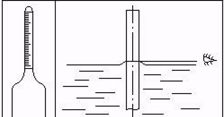
The essence of the method is to immerse the hydrometer in the test product and take readings on the hydrometer scale at the test temperature. The readings are taken along the upper meniscus, since the AN and ANT1 hydrometers are calibrated to the upper meniscus (see Fig. 4.1)
Rice. 4.1 – Determination of the density of petroleum products with a hydrometer
The cylinders can be glass or metal, their dimensions ensure that the hydrometer floats. The cylinders are installed on a flat, flat surface.
Thermometers must comply with GOST 28498 type A liquid or type TIN5 according to GOST 400-80 with a division value of 0.1 °C.
It is allowed to measure the temperature of the test sample before and after measuring the density using a hydrometer thermometer; for accurate measurements, use an additional thermometer. In this case, it is allowed to measure the temperature on the tank, and measure the density in the brought sample in the laboratory, bringing the test temperature in the laboratory to the temperature of the tank.
The reading on the hydrometer scale corresponds to the density of the product at the test temperature.
To measure the amount of oil or petroleum products over a known volume, the density is determined at the temperature at which the volume is measured.
GOST 3900-85 has Appendix 1, which is used to convert density values from the measured temperature to density values at 20 for filling out passports or converting volume and density to standard conditions (20 °C, P = 0).
GOST 3900-85 defines density measurement at pressure equal to atmospheric pressure. In order to take into account the pressure in the pipeline, if necessary, in addition to GOST 3900-85, methodological instructions MI 2153-2001 were published, which determine the procedure for converting hydrometer readings at atmospheric pressure and any temperature to the temperature and pressure at which the volume is known, and has an appendix to convert density from temperature t°C to 15 °C at atmospheric pressure, since currently the standard conditions are 15 °C, Pg = 0.
Density is recalculated taking into account temperature and pressure using formula 4.5:
 , (4.5)
ρar – density measured by a hydrometer;
β – coefficient of volumetric expansion, g -1;
tar - temperature when measuring density with a hydrometer, °C;
t – temperature at which the volume was measured;
γ – oil compressibility coefficient, MPa -1, given in MI;
P – excess pressure at which the volume is determined.
Determination of density is carried out in a sample taken from tanks, containers, pipelines, railway and road tanks.
For the quantitative assessment of oil and petroleum products using the volumetric-mass static method, the sampling operation is as important as determining the density.
Sampling is regulated by GOST 2517-85.
Since, as a rule, oil and gasoline with a saturated vapor pressure below 750 mm Hg are subject to transportation through pipelines. Art. (below 100 kPa), then from this GOST we will be interested in the information that relates to these oils and petroleum products.
Sampling of product with P no.<750 мм рт. ст. из резервуаров типа РВС производится:
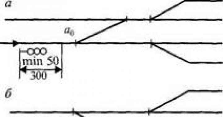
Stationary samplers with a perforated sampling tube located inside the tank from the gauging hatch to the bottom of the tank. To ensure that the mixing of all parts of the product along the height of the tube corresponds to the required ratio between the top, middle and bottom, perforations (holes) are performed at a distance in accordance with Fig. 4.2;
Stationary samplers providing product selection from three levels;
Portable samplers, which can be metal, bottles in a metal braid, thermostated.
For horizontal tanks and tanks, manual samplers are typically used.
Automatic and manual samplers are used to take samples from pipelines.
Schemes of sampling devices are shown in Fig. 4.2 – 4.5.

Rice. 4.2 – Sampling device with perforated tube
1 – maximum product level;
2 – tank body;
3 – perforated stand;

Rice. 4.3 – Sampling device with sampling from three levels
1 – float;
2 – supporting articulated arm;
3, 4, 5 – sampling tubes, open at the upper end;
6 – hinge;
7 – sampling valves

Rice. 4.4 – Portable sampler
1 – housing with inlet and tube, product included
under the influence of gravity;
2 – cover;
3 – fitting for the outlet of displaced air

Fig. 4.5 – Thermostatic sampler
1 – bottle;
2 – frame made of metal strips of rods with a weighted bottom;
3 – plug;
4 – rope ropes for lowering the sampler and opening the plug
Thermostatic samplers consist of a cylinder surrounded by an outer insulating coating. The top of the cylinder is closed with a stopper. Dimensions: height – 250 mm, diameter – 80 mm.
The sampler is used to transfer the sample from the reservoir to the laboratory if the ambient and product temperatures differ significantly from each other.
All portable samplers must have a mass that allows them to be immersed in the liquid layer in the tank and then installed on the bottom of the tank.
To take samples from a pipeline with a diameter greater than 400 mm, five-layer samplers are most often used (Fig. 4.6.). Five tubes located at different distances from the center make it possible to take a sample from 5 points along the diameter of the tube.

Rice. 4.6 – Five-layer samplers
1 – tubes;
2 – cover;
3 – external sampling tube;
4 – valve
Tube diameters:
d 1 – in the center of the pipeline (1 tube);
d 2 – 0.4 diameters from the center (2 tubes);
d 3 - 0.8 diameters from the center (2 tubes).
Ratio d 1:d 2:d 3 = 6:10:13. The calculation of the diameter of the tubes is determined from the condition: the fluid speed at the entrance to the sampling device must be no less than 1/2 and no more than 2 times the flow speed in the pipeline.
For automatic sampling, it is necessary to assemble an additional circuit, which looks like shown in Fig. 4.7
The sample is pumped by pump 5 and, using regulators 6, 7, at certain intervals, enters receiver 8. Locking device 7 is actuated by an electric, pneumatic or electromagnetic drive, which is activated according to a given program. Valve 4 and receiver 3 are provided for manual sampling when automatic sampling is not working.

Rice. 4.7 – Scheme for automatic sampling
1 – pipeline;
2 – sampling device;
3, 8 – sample receivers;
5 – pump;
6 – regulator;
7 – locking device;
9 – check valve;
The basic rules for sampling from tanks are as follows::
Before sampling, the product is allowed to settle for at least 2 hours, then water and contaminants are removed;
Spot samples of the product from the RVS can be taken with stationary or portable samplers from three levels:
upper – 250 mm from the surface of oil or petroleum product;
medium – the middle height of a column of oil or petroleum product;
lower – the lower generatrix of the inlet-dispenser pipe for oil and 250 mm from the bottom of the tank for oil products.
The combined sample for the tank is made up of point samples in a ratio of 1:3:1.
When the level height in the tank is 2000 mm or less, two samples are taken: from the upper and lower layers. The pooled sample is obtained by mixing selected samples in a 1:1 ratio.
If the fill in the tank is less than 1000 mm, take one sample from the lower level.
Sampling from tanks.
One point sample is taken from the tanks from a level located at a distance of 0.33 of the tank diameter from the lower generatrix.
For the route, the pooled sample is made up of point samples taken from every fourth tank and mixed in equal proportions.
Sampling from pipelines.
A sample of oil or petroleum product is taken from the pipeline with a stationary five-layer sampler only during the pumping process in the presence of a uniform liquid flow. It is advisable to place the sampler on horizontal sections and the outlet assembly of the sampling device should be located on top of the pipeline.
Point samples are taken either hourly or through certain volumes of pumped liquid. Combined samples per day, per batch (according to production needs) are made up of spot samples mixed in equal volumes. Automatic sampling from the pipeline is carried out using the above scheme. The frequency of collecting point samples that fall into the general sampler also depends on production needs.
Bottom sampling from reservoirs, cisterns, they are produced with portable samplers such as the metal portable sampler shown above, the liquid readings into which occur due to gravity or, in other words, the pressure force of the liquid column.
Sample storage is also important..
In the operations of receiving and delivering petroleum products to the pumping station, the combined sample is divided into two parts. One part is analyzed, the other is kept sealed in case of disagreement with the Consumer or Customer in assessing quality or quantity.
When transported on river vessels (tankers), the combined sample is divided into parts according to the number of recipients. One part is for analysis, the other is in case of possible disagreements, the rest is given to the recipients.
For export shipments by rail or pipeline, the combined sample is divided into three parts: one part for analysis, two parts in case of disagreement.
Samples must have labels indicating:
Sample number according to the magazine;
Type of product, specifications or GOST for this product;
Name of the supplier company;
Tank number, fill level;
Batch, tank, route number;
Date, time of sampling;
Shelf life;
Position, full name persons who collected and sealed the sample.
The neck of the sealed bottle is wrapped in polyethylene, tied with a cord, both ends of the cord are threaded into a hole on a plate of hard cardboard or wood, tied and the ends are either sealed or filled with sealing wax and sealed. Stored in a specially equipped room. Shelf life:
45 days from the date of shipment or delivery;
In case of export supplies, for oil – 3 months, for petroleum products – 4 months;
When delivered to the DPRK, China – 6 months.
Vladimir Khomutko
Reading time: 4 minutes
A A
How to determine the absolute and relative density of oil and petroleum products?
The density of oil and petroleum products is one of the most important characteristics of oil and petroleum products, which is why the accuracy of its determination is so important.
There are two indicators of this parameter - absolute and relative.
The absolute density of oil and petroleum products is the amount of mass per unit volume. It is measured in grams, kilograms and tons per cubic centimeter or meter (g/cm3, kg/m3). This indicator is determined at 20 degrees Celsius.
Relative density is the ratio of the density of light petroleum products or the density of oil and dark petroleum fractions to the value of this parameter for distilled water at certain temperatures of both liquids. This indicator has no unit of measurement. In our country it is determined at 20 degrees, and for distilled water at 4 degrees.
This indicator can be determined by the following methods:
- determination by hydrometer and densimeter;
- pycnometric method;
- calculation method.
Measuring the density of petroleum products using a hydrometer and densimeter
Hydrometers measure both the density of oil and petroleum products and their temperature, while densimeters measure only the density of petroleum products. This method is regulated by GOST 3900 - 85 and consists in immersing a calibrated hydrometer into the product under study, and then reading the readings on the instrument scale under current research conditions. After this, the result obtained is brought to a normal value at 20 degrees (there is a special table for this).
These measuring instruments have the following limits (g/cm³):
- aviation gasoline – from 0.65 to 0.71;
- motor gasoline – from 0.71 to 0.77;
- kerosene – from 0.77 to 0.83;
- diesel fuel and oils (industrial) – from 0.83 to 0.89;
- dark oils and petroleum products - from 0.89 to 0.95.
The research process proceeds as follows:
| № | Helpful information |
|---|---|
| 1 | The glass cylinder is installed on a flat surface |
| 2 | then a pre-taken sample of the test product is poured into it so that no air bubbles form and there is no loss of volume due to evaporation |
| 3 | bubbles that appear on the surface are removed using filter paper |
| 4 | measure the temperature of the sample before and after measurement, using the same hydrometer, or, in the case of using a densimeter, with a separate device (the sample temperature must be constant with deviations of no more than 0.2 degrees) |
| 5 | carefully lower a dry and clean device into the vessel, holding it by the upper end |
| 6 | when the meter stops oscillating, read the readings from the upper or lower meniscus (depending on the calibration) |
| 7 | the result obtained is the density of oil or oil product under current conditions |
| 8 | the test temperature is rounded to the nearest one, which is in the table |
| 9 | using the same table, using the results obtained, determine the indicator of this parameter of the petroleum product at 20° Celsius |
The essence of the method is that a sample of the product being tested is poured into a pycnometer, which is a graduated vessel, then it is heated (or cooled) to 20° and weighed on special scales, the error of which is no more than 0.0002 grams. The result obtained is a relative indicator.
This calculation is based on the dependence of this parameter on the temperature of the oil product.
Sequence of calculations:
- an indicator of its density at 20° is taken from the passport of the product under study;
- measure the average temperature of the test product;
- calculate the difference between the obtained result and 20°, rounding it to the nearest whole number;
- in a special table, find the correction for one degree of deviation, which corresponds to the passport value of the parameter at plus 20°;
- the resulting determinant correction is multiplied by the temperature difference;
- the obtained result is added to the passport if the temperature of the study is below 20°, or subtracted from it if T > 20.
0,650…0,659 – 0,000962; 0,660…0,669 – 0,000949; 0,670…0,679 – 0,000936;
0,680…0,689 – 0,000925; 0,6900…0,6999 – 0,000910; 0,7000…0,7099 – 0,000897;
0,7100…0,7199 – 0,000884; 0,7200…0,7299 – 0,000870;0,7300…0,7399 – 0,000857;
0,7400…0,7499 – 0,000844; 0,7500…0,7599 – 0,000831; 0,7600…0,7699 – 0,000818;
0,7700…0,7799 – 0,000805; 0,7800…0,7899 – 0,000792; 0,7900…0,7999 – 0,000778;
0,8000…0,8099 – 0,000765; 0,8100…0,8199 – 0,000752; 0,8200…0,8299 – 0,000738;
0,8300…0,8399 – 0,000725; 0,8400…0,8499 – 0,000712; 0,8500…0,8599 – 0,000699;
0,8600…0,8699 – 0,000686; 0,8700…0,8799 – 0,000673; 0,8800…0,8899 – 0,000660;
0,8900…0,8999 – 0,000647; 0,9000…0,9099 – 0,000633; 0,9100…0,9199 – 0,000620;
0,9200…0,9299 – 0,000607; 0,9300…0,9399 – 0,000594; 0,9400…0,9499 – 0,000581;
0,9500…0,9599 – 0,000567; 0,9600…0,9699 – 0,000554; 0,9700…0,9799 – 0,000541;
0,9800…0,9899 – 0,000528; 0,9900…1,000 – 0,000515.
To better understand this technique, consider an example.