have conversion curves that are not shown when depicting turnouts in the axes. In the case shown in Fig. 2.16, V, the limit column is located on the outside of the curve.
Signals and their installation
To ensure the safety of train movement and shunting operations, the following signals are installed at stations:
Entrance - for fencing stations from the side of the tracks;
Weekends - allowing or prohibiting the train to go to
distillation;
Route - allowing or prohibiting the train to proceed
from one station area to another;
Shunting - allowing or prohibiting maneuvers.
Signals are installed on the right side of the track in the direction of train movement. The minimum width between paths in which the signal is installed is determined by the formula (E = b 1+ 26 2); to install mast traffic lights with stairs, a distance between the track axes of at least 5.20 m is required. When installing mast traffic lights without stairs, a distance between the track axes of 5.04 m is required.
 |
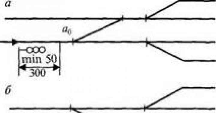
Input signals are set (Fig. 2.17):
If the first turnout is anti-hair, the input signals are set
flow at a distance of at least 50 m at
diesel traction and at least 300 m at
electric locomotive traction (Fig. 2.17, A) from the beginning of witticisms;
If the first turnout is wool, then the signal is set from
limit column at a distance of at least 50 m with diesel traction and at least
300 m with electric traction (Fig. 2.17, b).
With electric traction, the distance to the input signals increases to 300 m, taking into account the air gap separating the overhead contact network from the station contact network.
A turnout switch is called an anti-hair switch if the movement occurs at the points. If the movement of the rolling stock is directed towards the crosspiece, the switch will be smooth.
Output signals. There are three cases of installing output and shunting signals (Fig. 2.18).
Happening 1 - the limit column limiting the length of the path at a given end of the station (park) is located in the same interpath with the output signal from this path. The distance from the center of the turnout to the signal is determined in the same way as to the limit column, but the value R should be taken equal to half the distance between paths that allows us-

setting up signals. For practical purposes, tables of distances to signals have been developed depending on the brand of the cross, the width of the interpath and the radius of the curve (Appendix B).
Happening 2 - a signal located at different interpaths with a limit column for a given path is installed in a section with an insulating joint, i.e. at a distance of 3.50 m from the limit post.
Happening 3 - the output signal, behind which the anti-hair switch is laid, can be installed in alignment with the joint of the frame rail, i.e. on distance A from the center of the turnout.
2.9. Total and useful length of paths
There are total and useful lengths of station tracks.
The total length of the through track is measured between the points of the turnouts leading to it. The total length of dead-end tracks is measured between the points of the switches leading to that track and the stop. When calculating the total length, it is necessary to ensure that all paths, exits and switch streets are taken into account and at the same time not allow the same elements to be counted twice.
The useful length of the tracks is the part of the total length on which the rolling stock is installed without compromising the safety of traffic on adjacent tracks. The useful length of tracks can be limited by limit posts, output or shunting signals, turnouts, and stops. In Fig. 2.19, the useful length of paths 1, 2, 3, 4 and 5 is calculated from the limit column to the output signal. For tracks that have output signals for train departures in odd and even directions, the useful track length is determined separately for each direction.

leniya. In Fig. Figure 2.19 shows in parentheses the case of setting the signal CH 3 (2) - the second case of installation.
On the Russian railway network, standard useful lengths of 850, 1050 and 1250 m have been established for the receiving and dispatching tracks of freight traffic. On some railways, for the passage of empty trains of 100 cars each, the receiving and dispatching tracks have been extended to 1,500 meters or more. The useful lengths of the tracks of freight and industrial stations for the reception and departure of freight transfers can be designed less than the standard length, but not less than the length established depending on local conditions.
In order to run trains over long distances without changing their weight and length, special calculations are used to determine the most advantageous weight and length of trains on related routes for the tenth year of operation and select a standard useful length.
On new lines of categories I and II, as well as especially heavy-duty lines, the useful length of tracks must be at least 1050 m.
Track parks and station necks
A park is a group of paths of the same purpose, united by common necks. There are reception, departure, reception and departure parks, sorting parks, passenger train parking, and technical parks.
Depending on the purpose and operations performed, parks are:
Reception - to receive trains arriving at the station and perform
conducting operations with them upon arrival. Reception parks are available at precinct stations,
marshalling, freight and passenger stations;
Departures - for departure of finished trains, trailer trailer
locomotive and technological operations. Departure parks
available at marshalling, passenger, and cargo stations;
Reception and departure parks - for the reception and departure of trains. Ta
There are some parks at local stations, and can also be at passenger stations.
kih and freight stations;
Technical parks are set up at passenger stations, where operations for processing passenger trains are carried out (inspection, repair, equipping passenger trains and waiting for delivery for departure).
Other specialized parks are also located at stations.
Depending on the shape, parkas are used: in the shape of a trapezoid (Fig. 2.20, a and b), fish (Fig. 2.20, V), parallelogram (Fig. 2.20, d), combined (Fig. 2.20, G).

In a park shaped like a trapezoid (Fig. 2.20, A), all paths have different lengths, increasing as they approach the axis of the main path. With a significant number of paths, the difference between the paths will be quite significant. Therefore, parks in the shape of a trapezoid are used only for a small number of paths (up to three or four).
Park trapezoid (Fig. 2.20, b) has a switch street along the main path at one end, and a cross at the other end. In this park, all paths, except the extreme ones, are approximately equal in useful length with convenient access to the main path.
Park "fish" (Fig. 2.20, V) is a combination of two trapezoids or two trapezoids located on either side of the main path. This form of park is the most common, since with a large number of tracks, a compact arrangement of turnouts in the necks is ensured and the length of the necks is significantly reduced.
The combined form of the park is used for a large number of paths and is a combination of several forms of parks and combined turnout streets (Fig. 2.20, G).
Parkas in the form of a parallelogram (Fig. 2.20, d) are being built as technical and reserve parks. The advantage of this park is the same usable length of almost all the tracks, the disadvantage is the long turnout streets and the absence of a direct main path.
Station necks And parks A group of turnouts, exits and turnout streets connecting tracks and parks with each other, as well as with main, exhaust and running tracks, is called necks. Access and connecting roads are also adjacent to the necks. Neck designs are very important for the proper operation of stations. They must ensure traffic safety, the necessary throughput and good maneuverability, as well as be compact and take up as little space as possible.
Traffic safety is ensured by isolating each route of a train, locomotive, or train from other movements that may be in the neck. Isolation is provided by devices for electrical centralization and blocking of arrows and signals.
The required throughput (the number of units of rolling stock that can be passed through the neck in any period of time) is ensured by the presence of parallel passages. They allow you to perform several operations (movements) in the neck at the same time.
Maneuverability is achieved by the interchangeability of parks and paths, as well as the presence of exits that allow the use of several routes for simultaneous movement.
The necks should be simple and compact without unnecessary switches and ramps laid on the main tracks.
In Fig. Figure 2.21 shows an example of a simple neck. To perform multiple operations simultaneously, paths are combined into sections. There are four sections in the neck, three or two main paths and an exhaust

path, therefore, three movements can be performed simultaneously, since the maximum number of simultaneously performed movements is equal to the number of approaches to the neck.
In the neck in Fig. 2.21 from section I you can send a train along track I, along track II you can take a train to section III, and along the exhaust track you can enter section IV. At the neck, a train can also be sent from section II along main track I. In addition, the neck provides the possibility of departure from all sections (by laying exits 2-4 and 14-16), the possibility of receiving along the II main route to any section (by exits 10-12 and 14-16), the possibility of entering any section from the hood (on exits 6-8 and 10-12). The laying of exit 22-24 allows you to take from track II to the second section and at the same time send from the first section along the first main track.
In the necks, in cramped conditions (with insufficient space) to reduce the length of the neck, cross ramps and turnouts are laid.
Numbering of tracks and turnouts
At the station, each track, turnout and signal has its own number (Fig. 2.19). It is not allowed to assign the same numbers to tracks within the same station, and at large stations within the same park. Turnout numbers should not be repeated within the same station. When numbering, the following rules should be followed.
The main tracks are numbered with Roman numerals depending on the direction of travel: on double-track and multi-track lines, the tracks of odd trains are assigned odd numbers I, III, and the tracks of even trains are assigned even numbers II, IV. If single-track lines are adjacent to a double-track line, then the main tracks of the single-track lines are assigned numbers III, IV, etc.
On the Russian railway network, it is customary to consider the movement of trains from North to South and from East to West as odd, from South to North and from West to East as even.
Reception and departure tracks are numbered in Arabic numerals, starting with the number following the number of the main track; and the tracks for receiving odd trains are numbered with odd numbers 3, 5, 7 for receiving even numbers
nal trains - even numbers 4, 6, 8. If the tracks are used to receive even and odd trains, they are numbered consecutively following the numbers of the main tracks (3, 4, 5, 6, etc.) from the passenger building to the field side.
The remaining station tracks are numbered in Arabic numerals sequentially, starting with the next number following the number of the receiving-from-sending track.
At large stations, parks are named according to their purpose: reception (P), departure (O), receiving and dispatching (PO), sorting (S), etc. When there are several parks for the same purpose, a number is added to the name, for example PO-1, or the words odd, even. In some cases, a letter designation is used (A, B, C, D and etc.).
If a station has separate parks for receiving odd and even trains, the tracks in the odd park are numbered with serial odd numbers, and in the even park - with serial even numbers.
Turnouts are numbered with odd numbers on the arrival side of odd trains and even numbers on the arrival side of even trains. Numbering starts from the input arrows. At stations with large track development, turnouts are numbered by park, and each park is assigned its own hundred numbers, for example, 100-199, 200-299, etc. The border between even and odd numbers is the axis of the park, and at stations with little track development - the axis of the passenger building. Turnouts on turnout streets and exits have continuous numbering (for example: exits 1-3, 2-4, turnout street 5-7-9-11, 6-8-10).
Signals on plans and diagrams of stations are assigned:
The even input is the letter H, the odd input is H without indices;
Weekend - the same letters with indices corresponding to the path number
(H 1,H 2>H 1,H 2, etc.).
2.12. Calculation of coordinates of station elements
In order to build a station, it must first be laid out on the ground; for this, the coordinates of all the main points of the station must be calculated: the centers of turnouts, limit columns, signals, vertices of rotation angles, etc. The point of intersection of the axis of the passenger building is often taken as the origin of coordinates ( axis y) and axis I of the main path (axis X). Ordinate X accepted conditionally with a sign (+) in any case, the ordinate at accepted with a (+) sign if the calculated point is located above the axis X, with a (-) sign if the point is located below the axis X.
Example. For the station diagram in Fig. 2.22 we accept: type of rails on the main tracks R-65, on other station tracks R-50; brand of cross 1/11 turnouts 1, 3, 5, 7, 9, 2, 4, 6, 8, the rest 1/9. The useful length of the receiving and departure tracks is 1050 m. Diesel traction. From the diagram it can be seen that the shortest path is 5, which is accepted as the calculated path; its length is taken to be 1050 m. Before starting the calculation of coordinates, it is necessary to carry out preliminary preparations for the calculation. The distances to the limit posts and signals are extracted from the appendix tables. Calculated or 160
 |
The calculated coordinates of the points are shown on the station plan. A list of paths is compiled, in which for each path its purpose, the boundary of the path, the total and useful length are indicated (Table 2.1). The list includes first the main routes, then the receiving and departure routes, then the exhaust routes, and then all the rest; at the end of the list, exits are indicated. The total and useful length is determined based on the obtained coordinates.

In the same way, the total and useful length of all paths is determined. For receiving and departure tracks that accept even and odd trains, the useful length is determined for even and odd directions of movement, and both values are indicated in the track sheet separated by a fraction. For exits, only the full length is indicated.
To determine the number of turnouts required during the construction or reconstruction of a station, a list of turnouts is compiled (Table 2.2). The list for each turnout indicates the brand, type of rails and direction: left or right, depending on the direction of deviation from the main track to the left or right.

Basics of designing separate points
Projects of stations and nodes are developed during the construction of new railway lines, additional main tracks on network routes, electrification of lines, development of stations when extending tracks, etc. as components of projects. And also as independent station development projects to increase the capacity of individual stations and nodes. In recent years, the issue of construction and design of port and border stations has become relevant. When reconstructing stations in order to increase capacity, the main work is: lengthening the tracks at stations of the main directions.
The preparation of project documentation is preceded by the development of Justification for Investment in Construction.
According to SP11-101-95, the Justification sets out the objectives of the investment, the economic, social and commercial effect expected from the operation of the facility. The main technological solutions are indicated, the choice of location of the facility is justified (the construction area of the designed railway station or interchange), the main construction solutions are indicated (the number of kilometers of station tracks to be laid and the resulting useful length of tracks, the main characteristics of bridges, tunnels), the timing and priority of construction, the need in material resources, considerations for organizing construction. The Justification evaluates the environmental impact of the facility and indicates the need for labor resources.
The Justification contains an assessment of the effectiveness of investments, which is based on the cost of construction, measured by aggregated indicators, clarified sources and conditions for financing investments, determining the cost of production (the throughput and processing capacity of the station, the weight of the train that the station can receive and send, during the construction of an interchange, its duration payback due to reduced operating costs). The Justification materials are sent to the relevant executive authority for registration
The act of selecting a land plot (route) for construction. Approval of the Justifications by the customer is carried out on the basis of the conclusion of the state examination and the decision of the executive authority to approve the location of the facility.
Design stages. Project documentation is developed on the basis of approved Justifications for investments in construction, technical specifications for design drawn up by the customer, and engineering survey materials. The procedure for the development, composition and content of design documentation for construction are established by the Construction Norms and Rules of the Russian Federation SNiP 11-01-95.
Design is carried out in two stages or for small objects in one stage.
1. In two-stage design, a feasibility study (Project) is developed and
working documentation.
2. With a one-stage design, a working document is developed
mentation (approved part).
The feasibility study (Project) must contain:
1. General explanatory note.
2. Master plan of the station (for a node - master plans of all stations
tions to be developed).
3. Technological solutions.
4. Architectural and planning solutions.
5. Power supply, communications, signaling systems, locomotive and carriage facilities.
6. Organization of construction.
7. Environmental protection.
8. Estimate documentation.
The general explanatory note includes: the design assignment approved by JSC Russian Railways, characteristics of the design area, characteristics of the existing transportation organization (dimensions of freight and passenger traffic, train weight, series of locomotives, freight traffic and car flow).
Based on the size of the movement, the station devices are determined - the number of receiving and dispatching and sorting tracks, exhaust tracks.
The station operation technology is established and neck designs are developed. A traction service system is being developed. For the node, the locations of the main depot and equipment devices, and the change points for locomotive crews are determined. The issue of wagon facilities is being resolved.
Drawings for plans are being developed - on a scale of 1:2000 and 1:1000, transverse profiles on a scale of 1:200, longitudinal profiles - in accordance with GOST.
In the working documentation, drawings are developed, according to which construction, transverse and longitudinal profiles can be carried out, and coordinates are calculated for the plans. The scope of work is determined and estimated costs are drawn up.
Related information.
To indicate the boundary within which rolling stock can be located without disturbing the safety of traffic on the adjacent track, special signal signs are provided - limit posts. They are installed for station tracks (except for receiving and departing tracks equipped with electric rail circuits) in the middle of the intertrack on the side of the turnout cross, where the distance between the axes of diverging tracks is 4.1 m.
The distance from the translation center to the limit column installed between two diverging straight paths is determined by the formula:
Where R- distance from the limit column to the axis of the straight path, R= 2.05 m; a is the angle of the turnout cross.
In cases where, after branching, the paths run parallel to each other and one of the paths has a curve, the distance from the axis of the curved path to the limit column is R+ A, where A is the increase in the overall distance to structures located on the inside of the curves (see Fig. 4.2, A). With curve radius R= 200 m A = 0.18 m, at R= 300 m - A = 0.12 m.
If there are curved sections of the path, the installation location of the limit column is determined by calculation. In this case, the distance from the limit column to the center of translation /pr depends not only on the brand of the cross, but also on the width of the space between the paths and the radius of the curve:

Rice. 4.2. Schemes for installing limit posts: on the inside of the curve (a); from the outside of the curve ( b) I - projection onto the horizontal axis of the distance from the center of the turnout to the limit column; R - the distance from the track axis to the limit column on a straight section of the track; p + D is the distance from the track axis to the limit column within the curve; e - distance between paths; T - tangent of the curve; R- radius of the curve; a is the angle of the cross where e- width of the track, m; T - tangent of the curve, m; R- curve radius, m.
The value of the angle p at e > 2p + A is determined from the expression:
In the case shown in Fig. 4.2, 6, the distance from the center of the turnout to the limit column is determined from the expression:
Where by- distance from the center of the turnout to the beginning of the cross curve along the side track (determined according to Table 4.1); D n - increase in overall distance to structures located on the outside of curves, D n = D.
The value of the angle p is found from the expression:
Table 4.1
Distance values from the center of the turnout to the beginning of the cross curve along the side track
On receiving and departure tracks equipped with electric rail circuits, insulating joints must be placed at a distance of 3.5 m behind the limit column. In order to use standard inserts (12.5 m and 6.25 m) on the section of the path from the end of the cross to the insulating joint, it is possible to increase the distance from the center of the transfer to the limit column in comparison with the calculated one according to the conditions of the approach clearance of buildings.
To ensure safety and regulate train and shunting traffic within the station, special signals are installed: entrance, checkpoint, route, exit, warning etc. Signals are installed on the right side in the direction of movement or above the axis of the track. The layout diagrams of output, shunting and route signals relative to the center of the turnout and limit columns are shown in Fig. 4.3.
There are three possible cases of setting signals (indicated by numbers in Fig. 4.3):
- 1. The limit column that limits the length of a given path is located in the same interpath with the output signal from this path. The distance from the translation center to the signal is determined in the same way as to the limit column, but the value R is accepted halfway between paths allowing the installation of this signal;
- 2. A signal located in different spaces between the paths with the limit column for a given path or outside the extreme path is installed in a section with an insulating joint, i.e. at a distance of 3.5 m behind the limit column;
- 3. The signal, behind which the anti-hair turnout is laid, can be installed in alignment with the joint of the frame rail, i.e. on distance A from the translation center.
Input signals for diesel traction are installed at a distance of at least 50 m from the tip of the first oncoming turnout along the route and from the limit column if the first turnout is cross-cut. On electrified lines, input signals are removed from the first turnout by

Rice. 4.3.
/R h'h ~ distances from the center of the turnout to the limit column for the corresponding case; /pr - projection onto the horizontal axis of the distance from the center of the turnout to the limit column
300 m, taking into account the air gap separating the contact network of the stage from the contact network of the station.
Input signals define station boundaries on single-track lines. On double-track lines, station boundaries are established separately for each main track. On the arrival side of trains, the station boundary is the entrance signal, and on the departure side, the “Station Boundary” signal sign is installed at a distance of 50 m behind the last exit switch.
If the last turnout is laid with a cross towards the section, a distance of 50 m is measured from the limit column.
ABC of travel signs
Many passengers, looking out the window, have probably wondered more than once: what are these sophisticated signs, pointers, designations with letters and numbers that stretch along the route, sometimes on poles, sometimes on poles, painted either in one color or in stripes? These signs are truly wise, like the science of any precise craft. .
Waysigns used to designate a particular place on the railway track. They are necessary for the driver when driving a train, planning and carrying out track work, recording the location of structures, the water level in areas of floodplain embankments and in a number of other cases. Waymarks include kilometer signs, incline signs, picket signs, benchmarks for the beginning and end of circular curves, and special waymarks
Kilometer signs installed on the right side of the path (in the direction of counting kilometers) no closer than 3.1 m from the axis of the outermost path in excavations (except rocky ones) and at the exits from them (over 100 m) kilometer signs are placed no closer than 5.7 m from the axis of the outermost ways. The pole is painted gray, and its bottom and upper pointed part are painted black. On the main lines, on the top of the poles, a flat white plate indicating kilometers from Moscow is attached edgewise to the railway track.

Previously, kilometer posts were called mile markers, they were striped, like mileposts on highways and highways, and measured miles accordingly. In the book "Railroads 1825-1925", published in 1925, the author writes: “To indicate versts, pickets, slopes and curves, as well as to indicate the boundaries of sections, districts (the original spelling is preserved) of road workers, departments of senior workers, etc., “way signs” are placed on the edge of the roadbed, which must have a clear inscription, clearly visible from the train. Track signs are usually made from old rails with corresponding inscriptions on them using oil paint. Pickets are marked with low stone pillars, painted white, indicating a serial number from one to nine; The tenth picket is not set up, since there is a milestone in its place.”
Picket signs(made of wood, stone or concrete) usually 500 mm high, installed on the side of the roadbed. In areas where there is little or no snow, stone and concrete picket signs can be 300mm high. The signs are painted gray, and the top and bottom of the wooden signs are painted black. On each sign, numbers 120 mm high indicate the numbers of the ended and started pickets of a given kilometer. The numbers are written in black paint on two opposite sides of the sign, located across the canvas.

Picket signs (a – wooden, b – concrete)
Benchmarks the beginning and end of the circular curve (Fig. 3 95) are made of stone or concrete, installed on the right or left side of the railway. path no closer than 3.1 m from its axis opposite the beginning and end of circular curves. The letters indicated on the posts have a height of 35 mm with a vertical distance between the letters of 15 mm and indicate: NKK - the beginning of a circular curve, KKK - the end of a circular curve, PC - the number of the previous picket plus the distance from it to the beginning (end) of the curve in meters ; Р – radius of the circular curve in meters; B – elevation of the outer rail in meters.

Benchmark of the beginning (or end) of a circular curve
In the old days, the path was also marked grade indicators. They were canceled at the turn of 1950-1960. The wing of the incline indicator looked up or down, depending on the elevation or slope of the path, and indicated the beginning of the slope and its size in “thousandths”. A slope indicator was installed at the fracture sites of the longitudinal profile. The position of the plate indicates the nature of the profile element in front (slope, rise, platform), and the numbers indicate the steepness of the element in thousandths and its length.

Inclination indicators were needed as long as rolling stock was on towbars - that is, with screw couplers or couplers (screw harness), and not with automatic ones, as now. Since the late 1930s, the introduction of automatic coupling began and gradually the need for incline signs disappeared.
Special-purpose track signs installed and maintained by railway workers include signs indicating the location of hidden subgrade structures (inspection wells, sub-ditch drains, adits, etc.); highest water horizon and maximum wave; railway borders right of way, etc.
Signal signs installed along the track require certain actions from the personnel involved in train shunting work: “Lower pantograph”, “Raise pantograph”, “Start pushing”, “End pushing”, “Attention current breaker”, etc.
Previously, with steam locomotives, there were many not only now obsolete professions, but also signal signs along the way, such as "Close the siphon" And "Close the vent " Everyone knows the expression “siphoned” - that is, it blew through. So the siphon actually creates artificial draft in the furnace of a steam locomotive, which makes the fuel burn much more actively. The assistant driver opens the tap on the boiler, and steam begins to flow forcefully into the pipe from the siphon ring. When the siphon is turned on, especially if the locomotive is running on coal or wood, it raises sparks and sometimes large burning pieces of fuel from the locomotive pipe. When a steam locomotive with a strongly open siphon passed under a bridge (and in steam locomotive times, that is, until the mid-1960s, many pedestrian, road, narrow-gauge bridges and overpasses were still entirely wooden), the bridge could be set on fire or there could be strong smoke, dangerous for pedestrians.

Sign “Close the vent” was placed in front of the pedestrian decks and bridges that are located under the locomotive. In the old days, burning flakes of slag and pieces of flaming coal littered the path from under the steam locomotive. The path along which steam locomotives ran on solid fuel (coal, firewood, shale, peat) was always recognizable. There were cases when entire stations burned down due to the arson of wooden sleepers and beams by falling locomotive heat. Sign “Close the vent” forced the locomotive crew to close the ash pit in a dangerous place. The new locomotives produced in the 1930s-1950s had large bunker ash pits, through which much less slag spilled from the furnace, but signs “Close the vent” They continued to stand for a long time, until the locomotives left completely.
Signs "Start of pushing" And "End of Pushing" limit the place on a long rise where pushing of trains by a pusher locomotive should begin and end.

Sign "Station Boundary" - this is the place where the stage ends and the station tracks begin - another service subordination.
And here's the sign "Conductor" more cunning: this is not at all the conductor that the uninitiated might think about, here the meaning is different. Previously, when there were no radio stations on locomotives and no message could be conveyed to the driver, if the entrance semaphore or traffic light that fenced the entrance to the station malfunctioned, the train, according to instructions, had to be met by a representative of the station duty officer (express) - he was called the conductor. In his hand he held a painted tin or steel sign with an embossed inscription: “Conductor ticket No. such and such, station such and such, for receiving even or odd trains.” Having received this ticket, the driver received the right to enter the station accompanied by this same conductor. So this is the place where the conductor was supposed to meet the train, and was indicated by a sign "Conductor".
Way signs also include limit bars – they are installed in the middle of the track where the distance between the axes of the converging tracks is 4100 mm (normal track spacing on stretches). On station tracks, a distance of 3810 mm is allowed.

Limit columns: a – for main and receiving and departure tracks; b – for station tracks
On transfer tracks with narrowed track spacing, limit posts are placed in places where the track spacing reaches 3600 mm. On curved sections, this distance should increase as the radius of the rail track decreases. On the marginal posts of park paths, on the sections facing the arrows, indicate the numbers of the tracks between which the post is located. These signs indicate "limit"- a place beyond which the carriage cannot be parked. In common parlance, railway workers call these columns “the limit” or “passage” and say, for example: “it’s beyond the limit”, “there are passages”, “they moved beyond the passage” - that is, the tail of the train fits behind the limit column. In the old days, there were also columns that indicated the boundaries of plots, distances or subdivisions. They were called boundary posts from the words “border” or “edge”.
IN “Regulations on signals on railways in Russia” dated January 31, 1873 limit bars are referred to as Train stop signs:
“§33. Train station signs . On station tracks, special posts painted red should mark those parts of the tracks where trains and rolling stock in general can be placed when stopping. These posts are placed at all corners of converging paths, at such a distance from their junction that the width between the paths is not less than 6 ½ feet. (0.93 fathoms).
Note . An exception is allowed only for the Nikolaev Railway, where bollards can be installed at such a distance from the junction of tracks where the width between tracks is at least 5 ½ feet. (0.79 fathoms).”
And in "Rules about signals", published in 1897 Moscow-Kazan railway In chapter " Station signals" the following definition is given:
“Indicating the location of trains on station tracks: Limit posts placed between the tracks. The train or individual cars must not cross these posts, i.e. thereby approaching the intersection or branching of two adjacent paths.”

Special railway food - temporary portable wayfinding signs. This is purely railway specific. Some of them have already been described above (“ Station boundary", "Conductor" ). There are still signs “Stopping the locomotive”, “Stopping the first car”, “Raise the pantograph”, “Lower the pantograph”, “End of the catenary”, etc.

Sign "C" means giving a long whistle at this place. This sign can be installed on a pole, panel or catenary support.
Signs "The Beginning of a Dangerous Place" And "The End of a Dangerous Place" limit the space on the track that the train needs to pass with a decrease in speed, often very significant, for example, during track work.
Very original and expressive signs exist to provide instructions to the snow removal manager. Track workers install them only for the winter before crossings and in general in any oversized place where a snowplow while moving can hit a protruding surface with a knife or wings and go off the rails. Sign "Raise the knife, close the wings" is installed on the right side along the train at a distance of 30 m (and in areas where high-speed snowplows operate - 50 m) in front of the obstacle (crossing deck, bridge, etc.). Sign “Lower the knife, open the wings” – at a distance of 10 m behind the obstacle.
"Green Shield", "Yellow Shield", "Red Shield" - the locomotive crew calls these portable signals out loud while driving the train, immediately indicating the speed at which you can follow after passing the sign. For example, “Yellow shield, speed sixty,” announces the assistant. “Yellow shield, speed sixty,” the driver repeats. These signs indicate that the train speed limit is 60 km/h ahead. When the place where the speed is reduced is left behind at a distance of a standard length for circling trains, there is a green sign next to the track - keep the set speed, that is, the one at which you can travel along a given stretch or station. And the red shield is a sign that generally prohibits any forward movement. To make it more convincing, they place it not next to the track, but right between the rails. It’s like a car driver’s “brick” sign.
Warning signs "Beware of the train » at crossings are installed on the road leading to the railway. tracks at a distance of 20 m from the outer rail on the right side in the direction of vehicle movement. A sign is installed at a distance of 50 m from the outermost rail "Attention! Automatic barrier."
There is a sign called " Speed reduction dial" which is fixed on a pole installed on the side of the roadbed.

Railway track signs are a precise, silent and therefore especially attractive professional language. Columns, signs, signals - knowing all this wisdom was both responsible and very honorable. In the eyes of the respectable public, railway workers seemed to be people of significant and skilled work and commanded respect. Everyone clearly knew and did their job and was responsible for it. Everything had a meaning and order. It was a mathematically precise industry that worked like clockwork around the clock. Everything in it was determined by technical feasibility.
In preparing the article, materials were used from Alexey Vulfov’s book “Daily Life of Russian Railways”, Moscow, “Young Guard”, 2007, as well as:
1. Katikman, A. A. Railways 1825-1925 / A. A. Katikman; ed. S. D. Kareisha. – L., 1925. - 100 p. – From the contents: Route signs. P. 82.
2. “Big encyclopedia of railways.” transport", Moscow, "Big Russian Encyclopedia", 2003.
3. Rules for the technical operation of railways open to public use: approved. by resolution of the Minister of Railways. 8 Feb. 1898 - St. Petersburg, 1898. - 87 p. – From the contents: About limit columns and signs. – pp. 35-36.
GOST 8442-65
Group D58
STATE STANDARD OF THE USSR UNION
TRAIL AND SIGNAL SIGNS OF RAILWAYS
Track and signal signs of rail roads
Date of introduction 1966-01-01
INTRODUCED by the Ministry of Railways
APPROVED AND ENTERED INTO EFFECT by the State Committee of Standards, Measures and Measuring Instruments of the USSR on April 17, 1965.
REISSUE (December 1982) with Amendments No. 1, 2, approved in April 1976, April 1981 (IUS 6 - 1976, 7 - 1981).
AMENDED Change No. 3, approved and put into effect by Resolution of the USSR State Committee for Product Quality Management and Standards dated 06.27.90 N 1906 from 01.01.91
Change No. 3 was made by the legal bureau "Code" according to the text of IUS No. 10, 1990
This standard applies to track and signal signs on 1520 (1524) mm and narrow gauge railways.
The standard does not apply to special signs for in-plant transport of industrial enterprises.
The standard takes into account the requirements of the Convention on Road Signs and Signals (1968) and the European Agreement supplementing the Convention on Road Signs and Signals.
The requirements established by this standard are mandatory.
I. SHAPE AND SIZES OF SIGNS
I. SHAPE AND SIZES OF SIGNS
The shape, dimensions of track and signal signs, the location of inscriptions, as well as the sizes of letters and numbers must correspond to those indicated in Figure 1-44.
1. TRAFFIC SIGNS
Damn.1. Kilometer sign
Kilometer sign
Damn.1
The sign is installed to sequentially count kilometers from Moscow on the main railway lines determined by the Ministry of Railways.
The serial numbers of kilometers must be shown on both sides of the plate. On one side is the number of the kilometer that ends before the sign, on the other - the number of the kilometer that begins after the sign.
The sign must be attached to the top of the post.
Damn.2
The sign is installed to sequentially count kilometers from the beginning of the railway or its line, the access road on other sections of the railways and access roads.
Damn.3. Picket sign
Picket sign
The serial numbers of the pickets must be depicted on two opposite sides of the post, perpendicular to the axis of the track. On one side of the post the number of the picket that ends in front of the sign is marked, on the opposite side - the number of the picket that begins behind the sign.
Damn.4. Incline sign
Incline sign
The first number on the sign must indicate the amount of ascent or descent on the section of the road following the sign; The numbers after the dash indicate the length of the path with this profile.
Signs must be installed perpendicular to the axis of the track.
A sign located perpendicular to the axis of the post must indicate the site; with an upward slope from the pillar - ascent, with a downward slope from the pillar - descent.
2. SPECIAL TRAVEL SIGNS
Damn.5. Railway right-of-way boundary sign
Railway right-of-way boundary sign
The plate (or the plane of the pillar on which the letters and images of the hammer and sickle are applied) must be installed parallel to the axis of the path.
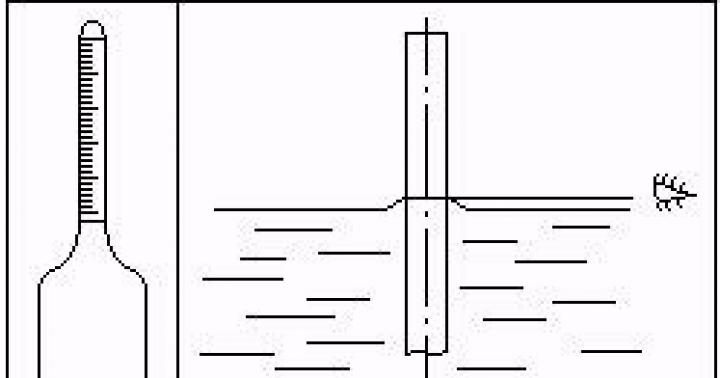
Damn.6. Sign of the highest water horizon and maximum wave height
Sign of the highest water horizon and maximum wave height
The sign must contain numbers indicating the distance in meters from the bottom line of the ring:
upper - up to the maximum wave height;
the lower one - to the highest water horizon.
Damn.7. Signs of hidden subgrade structures
Signs of hidden subgrade structures
The sign must indicate:
in the first line - the symbol for the hidden structure of the roadbed;
in the second - the number of the structure;
in the third - PC and picket number;
in the fourth - the year the structure was built.
The sign (or the plane of the post on which the inscriptions are written) must be installed parallel to the axis of the track.
Signs are installed by relevant ministries and departments.
Damn.8. Picket signs
Picket signs;
benchmarks of the beginning and end of circular curves, the beginning, middle and end of transition curves; railroad right-of-way boundary signs, hidden subgrade signs made of stone and concrete
The inscriptions on these signs are applied according to drawings 3, 5 and 7.
The type of benchmarks for the beginning and end of circular curves, the beginning, middle and end of transition curves and the inscriptions on them are indicated in Figures 9 and 9a.
Damn.9. Benchmarks of the beginning and end of a circular curve (made of stone and concrete
Benchmarks of the beginning and end of a circular curve (made of stone and concrete)
The markers of circular curves indicate:
NCC - the beginning of a circular curve;
KKK - end of a circular curve;
PC - number of the previous picket plus the distance from it to the beginning (end) of the curve, m;
R - radius of the circular curve, m;
B - elevation of the outer rail, mm.
The following are indicated on the transition curves:
NPK - beginning of the transition curve;
CPC - end of the transition curve;
SPK - the middle of the transition curve;
O - elevation outlet, %.
In forest areas it is allowed to make them from wood.
Benchmarks are installed when they cannot be replaced by nearby permanent devices (contact network supports, artificial structures, etc.).
Devil.9a. Benchmarks of the beginning, middle and end of the transition curve (made of stone and concrete)
Benchmarks of the beginning, middle and end of the transition curve (made of stone and concrete)
Drawing 9a
(Introduced additionally, Amendment No. 2).
Signs on linear track buildings
On linear track buildings the following must be installed:
a) a sign indicating the kilometer on which the building is located.
The dimensions of the plate, as well as the location and size of the numbers on the sign must correspond to Figure 1;
b) a sign of the presence of a telephone in this building (see drawing 10).
Damn.10
Damn.10
A sign indicating the kilometer on which the building is located must be installed on the linear track building on the side of the main track in the upper left corner at a distance of 0.3 or 0.5 m above the windows and 0.3 or 0.5 m from the edge of the building.
Under this sign there is a sign indicating the presence of a telephone.
Damn 11. Passenger building axis signs
Passenger building axis signs
The sign must contain letters indicating:
O - axis;
P - passenger;
Z - building.
The passenger building axis sign must be installed on the side of the main track at a height of 0.5 m above the top of the first floor windows.
Damn.12. Arrow number sign
Arrow number sign
A sign indicating the arrow number must be installed perpendicular to the axis of the track on the frame of the transfer mechanism. It is permissible to paint the pointer number directly on the frame of the transfer mechanism or on the housing of the pointer drive with centralized control.
3. WARNING SIGNS AT CROSS-CROSSINGS
A. BEWARE OF TRAIN signs
a) at an unguarded crossing (without barriers)
Drawing 13. (Excluded. Amendment No. 3).
Drawing 13a, 13b
The sign is installed when a road crosses one railway track.
Drawing 13a, b. (Introduced additionally, Amendment No. 1. Amended edition, Amendment No. 3).
Drawing 14. (Excluded, Amendment No. 3).
Drawing 14a, 14b
The sign is installed when a road crosses two or more railway tracks.
Signs must be installed perpendicular to the axis of the road.
Drawing 14a, b. (Introduced additionally, Amendment No. 1. Amended edition, Amendment No. 3).
Damn.15. (Deleted, Amendment No. 1).
Drawings 16, 16a, 17, 17a. (Excluded, Amendment No. 3).
4. SIGNAL SIGNS
A. Permanent signal signs
Damn 18. Sign "ATTENTION! - CURRENT CUT"
Sign "ATTENTION! - CURRENT CUT"
Damn.18*
____________________
* Drawing 18. Modified edition, Rev. N 3.
Damn.19. Light indicator "LOWER POWER COLLECTOR"
Light indicator "LOWER POWER COLLECTOR"
The sign must be installed perpendicular to the track axis on overhead contact line supports or individual masts.
(Changed edition, Amendment No. 1).
Damn.20. Sign "LIFT POWER COLLECTOR"
Devil.20*
___________________
* Drawing 20. Modified edition, Rev. N 3.
The sign must be installed perpendicular to the track axis on supports or overhead cables of the overhead contact line.
(Changed edition, Amendment No. 1).
Damn 21. Sign "LIMIT COLUMN"
Sign "LIMIT COLUMN"
Reinforced concrete column
Wooden post
_______________
* Drawing 21. Modified edition, Rev. N 3.
The limit post sign at the main and reception and departure tracks must be installed so that the reinforced concrete posts have an edge with retroreflectors, and the wooden posts have a hewn flat edge with retroreflectors facing the direction opposite to the turnout or blind intersection.
For reinforced concrete columns, on the faces adjacent to the reflectors, the numbers of the tracks between which the column is installed are indicated.
The wooden posts have special notches on which the track numbers are indicated.
The limit post sign at other station tracks must be installed so that the edge formed by the intersection of the faces of the post with the numbers printed on them (indicating the numbers of the corresponding station tracks) faces towards the turnout or blind intersection.
(Changed edition, Amendment No. 3).
Damn 22. (Deleted, Amendment No. 2).
Damn 23. "STATION BOUNDARY" sign
"STATION BOUNDARY" sign
The inscription "STATION BOUNDARY" must be placed on both sides of the sign.
(Changed edition, Amendment No. 3).
Damn.24. Sign "APPROACH ROAD BOUNDARY"
Sign "APPROACH ROAD BOUNDARY"
The sign must be installed perpendicular to the axis of the track.
Devil.24a. (Deleted, Amendment No. 2).
Damn.25. Signs "BEGINNING OF A DANGEROUS PLACE" and "END OF A DANGEROUS PLACE"
_________________
* Drawing 25. Modified edition, Rev. N 3.
Signs must be installed perpendicular to the axis of the path.
B. Permanent warning signs
Damn 26. Sign "C" for blowing the whistle
Sign "C" for blowing the whistle
Devil.26*
__________________
* Drawing 26. Modified edition, Rev. N 3.
The sign must be installed perpendicular to the axis of the track.
Damn 27. Signs "START OF PUSHING" and "END OF PUSHING"
Signs "START OF PUSHING" and "END OF PUSHING"
Damn.27
The sign must be installed perpendicular to the axis of the track.
Damn 28. Signs "CLOSE SIPHON" and "CLOSE BLOWER"
Signs "CLOSE SIPHON" and "CLOSE BLOWER"
The sign is installed in the area with steam traction.
The sign must be installed perpendicular to the axis of the track.
It is allowed to install these signs on one pole.
Damn.29. "LOCOMOTIVE STOP" sign
"LOCOMOTIVE STOP" sign
Damn.29
Damn.30. Sign "STOP FIRST CAR"
The sign must be installed on poles or nearest permanent structures perpendicular to the axis of the path.
Damn.31. Sign "TURN OFF CURRENT"
Devil.31*
______________________
* Drawing 31. Modified edition, Rev. N 3.
The sign must be installed perpendicular to the track axis on supports or overhead cables of the overhead contact line.
Damn.32. Sign "TURN ON THE CURRENT ON THE ELECTRIC LOGO"
Sign "TURN ON THE CURRENT ON THE ELECTRIC LOGO"
Devil.32*
______________________
* Drawing 32. Modified edition, Rev. N 3.
The sign must be installed perpendicular to the track axis on supports or overhead cables of the overhead contact line.
Damn.33. Sign "TURN ON THE CURRENT ON THE ELECTRIC TRAIN"
Damn.33*
______________________
* Drawing 33. Modified edition, Rev. N 3.
The sign must be installed perpendicular to the track axis on supports or overhead cables of the overhead contact line.
The sizes and colors of both plates are the same.
(Changed edition, Amendment No. 2).
Damn.34. "END OF CABLE" sign
"END OF CABLE" sign
Damn.34*
______________________
* Drawing 34. Modified edition, Rev. N 3.
The sign must be installed perpendicular to the track axis on supports or overhead cables of the overhead contact line.
The letters shown on the plate may be cut out.
Damn.35. Signs "TRANSITION TO THE LATERAL CONTACT NETWORK" and "TRANSITION TO THE CENTRAL CONTACT NETWORK"
Signs "TRANSITION TO THE SIDE CONTACT NETWORK" and "TRANSITION TO THE CENTRAL
CONTACT NETWORK"
Damn.35
The sign must be installed perpendicular to the axis of the track.
These signs are not installed on the railways of the Ministry of Railways.
B. Temporary signal signs
Damn.36. Sign "PREPARE TO LOWER THE CURRENT COLLECTOR"
Sign "PREPARE TO LOWER THE CURRENT COLLECTOR"
Damn.36*
______________________
* Drawing 36. Modified edition, Rev. N 3.
The sign must be installed perpendicular to the track axis on supports or overhead cables of the overhead contact line.
(Changed edition, Amendment No. 1).
Damn.37. "LOWER POWER COLLECTOR" sign
"LOWER POWER COLLECTOR" sign
Damn.37*
______________________
* Drawing 37. Modified edition, Rev. N 3.
The sign must be installed perpendicular to the track axis on supports or overhead cables of the overhead contact line.
(Changed edition, Amendment No. 1).
Damn.38. Sign "LIFT POWER COLLECTOR"
Sign "LIFT POWER COLLECTOR"
______________________
* Drawing 38. Modified edition, Rev. N 3.
The sign must be installed perpendicular to the track axis on supports or overhead cables of the overhead contact line.
(Changed edition, Amendment No. 1).
Damn.39. "PREPARE TO RAISED KNIFE AND CLOSED WINGS" sign
"PREPARE TO RAISED KNIFE AND CLOSED WINGS" sign
Damn.39*
______________________
* Drawing 39. Modified edition, Rev. N 3.
The sign is installed perpendicular to the track axis in front of the “Knife Raise, Wings Closed” sign (Figures 40 and 41) in areas where high-speed snowplows operate.
"KNIFE RAISED, WINGS CLOSED" sign
The sign is installed perpendicular to the axis of the path:
a) in the presence of one obstacle;
Damn.42. Sign "KNIFE LOWER, WINGS OPEN"
Sign "KNIFE LOWER, WINGS OPEN"
Damn.42*
______________________
* Drawing 42. Modified edition, Rev. N 3.
The sign is installed perpendicular to the axis of the path.
The signs indicated in Fig. 40-42, at the customer’s request, can be produced without retroreflectors.
(Changed edition, Amendment No. 3).
D. Portable signal signs
Damn.43. Signs "BEGINNING OF A DANGEROUS PLACE" and "END OF A DANGEROUS PLACE"
Signs "BEGINNING OF A DANGEROUS PLACE" and "END OF A DANGEROUS PLACE"
______________________
* Drawing 43. Modified edition, Rev. N 3.
Signs must be mounted on poles perpendicular to the axis of the track.
The “End of a Dangerous Place” sign is placed on the reverse side of the “Start of a Dangerous Place” sign.
At the customer's request, signs can be produced without reflectors.
(Changed edition, Amendment No. 1,).
Damn.44. Sign "C" for blowing the whistle
Sign "C" for blowing the whistle
The sign must be attached to a pole perpendicular to the axis of the path.
II. TECHNICAL REQUIREMENTS
1. Signs must be manufactured in accordance with the requirements of this standard according to the drawings of the Ministry of Railways and GOST 10807-78 regarding technical requirements for signs according to drawings 13b, 14b.
(Changed edition, Amendment No. 1,).
2. The shape and dimensions of pillars (poles) for track and signal signs, as well as the method of attaching signs to them, are established according to the drawings of the Ministry of Railways.
3. Sign boards must be of durable and rigid construction.
4. Sign plates must be enameled or painted, except for signs according to drawings 13b, 14b.
Enameled plates must be made of pickled steel sheet in accordance with GOST 19904-74, sheet thickness from 0.8 to 1 mm; painted - from thin sheet steel in accordance with GOST 19903-74 or GOST 19904-74, sheet thickness from 0.9 to 2 mm, or from other materials with the necessary strength and resistance to atmospheric influences.
(Changed edition, Amendment No. 1,).
5. The pillars must be made of reinforced concrete. In forested areas, poles may be made of wood. It is allowed to use other materials (except metal) for the manufacture of poles that have the necessary strength and appropriate durability.
On electrified sections, signal and track signs “Attention! - current divider”, sign “Lower pantograph”, “Raise pantograph”, “Station boundary”, “Conductor”, sign “C” for blowing a whistle, “Start of pushing”, “End of pushing” ", "Turn off the current", "Turn on the current on the electric locomotive", "Turn on the current on the electric train", incline indicators - can be installed on overhead contact line supports (except for the supports on which traffic light heads and contact line disconnectors are installed).
(Changed edition, Amendment No. 1, 2).
6. Track and signal signs must be installed in accordance with the Rules for the Technical Operation of Railways of the USSR and the Instructions for Signaling on Railways of the USSR.
7. On narrow gauge railways, the distance from the ground or the level of the top of the rail head to the bottom edge of the sign plate can be changed by agreement between the ministries operating the roads, depending on the type of rolling stock in use.
8. The surface of the signs must be cleaned before painting. Painting is carried out over the ground in two layers with oil paints in accordance with GOST 8292-85 or pentaphthalic enamels in accordance with GOST 6465-76. The coloring should be even, without drips, wrinkles, stains and should not peel off.
(Changed edition, Amendment No. 3).
9. Inscriptions on signs or the edges of pillars are applied with black paints on a white background.
On wooden pillars of a railway right-of-way boundary sign, letters and an image of a hammer and sickle may be applied by burning.
(Changed edition, Amendment No. 1).
10. Sign plates on the front side are painted: according to drawings 1, 2, 4, 10, 11, 12, 23, 24, 28, 34 - white, the remaining signs - in the order indicated on the drawings. The reverse side of the plates is painted black.
(Changed edition, Amendment No. 1, 2,).
11. Columns must be painted gray, except for the lower part of the pillar - from ground level to a height of 250 mm, as well as the upper pointed part, which are painted black.
The text of the document is verified according to:
official publication
M.: Standards Publishing House, 1983
Revision of the document taking into account
changes and additions prepared
JSC "Kodeks"
Read also:
|
Answer.
A track sign is a permanent indicator of the profile and length of railway lines.
Signal sign - a conventional visible sign (a limit column, a sign indicating the boundaries of a railway station, blowing a whistle, turning off and on the current, etc.), with the help of which an order is given to a certain category of railway transport workers
Special track signs - boundaries of the railway right-of-way, arrow number indicator, passenger building axis sign, signs on linear track buildings, benchmarks of the beginning and end of circular curves, as well as the beginning, middle and end of transition curves, hidden structures of the roadbed, the highest water horizon and maximum wave height
Signal signs are installed, respectively, by the owner of the infrastructure, the owner of the non-public railway track on the right side in the direction of movement, and track signs - on the right side according to the number of kilometers at a distance of at least 3100 mm from the axis of the outer railway track.
In excavations (except rocky ones) and at the exits from them, track and signal signs are installed, respectively, by the owner of the infrastructure, the owner of the non-public railway track outside the ditches and chutes on the field side. In heavily drifted excavations and at the exits from them (within up to 100 m), these signs are installed at a distance of at least 5700 mm from the axis of the outer railway track. The list of such excavations is established, respectively, by the owner of the infrastructure, the owner of the non-public railway tracks. In electrified areas, signal and route signs can be installed on contact network supports, except for those supports on which traffic light heads, complete transformer substations, contact network disconnectors and arresters are installed.
Limit columns are installed in the middle of the intertrack in the place where the distance between the axes of converging railway tracks is 4100 mm. On existing station railway tracks, which are not used by railway rolling stock built to gauge T, it is allowed to maintain a distance of 3810 mm. On transshipment railway tracks with a narrowed inter-track, limit posts are installed in the place where the width of the inter-track reaches 3600 mm.
On curved sections of the railway track, these distances must be increased in accordance with the rules and regulations.
Signal, wayfinding and special waymarks must comply with the rules and regulations.
13. Installation and purpose of the limit column.
Answer.
Limit bars indicate the boundary within which rolling stock can be located on a given track without violating the safety of traffic on the adjacent track.
Limit posts for station tracks (except for receiving and departure ones equipped with electric rail circuits) are installed in the middle of the track in the place where the distance between the axes of the tracks diverging from the center of the switch is equal to 4100 mm . On existing station tracks, which are not used by rolling stock built according to gauge T, it is allowed to keep this distance equal until reconstruction 3810 mm.