Course work
Thermal calculation of turbine K-500-240
Introduction
Initial data
1. Brief description of the turbine design
Thermal calculation of a turbine unit
1 Construction of the steam expansion process in the h-s diagram
2.2 Calculation of the regenerative feedwater heating system
Selecting the number of stages of a given cylinder, breaking down the differences in steam enthalpy by stage
1 Distribution of heat drops across the stages of a steam turbine cylinder
4. Estimation of turbine power based on a given steam flow
Detailed thermal and gas-dynamic calculation of a given stage
6. Justification for the choice of profiles NA and RC according to the atlas
6.1 Calculation of the nozzle array
2 Calculation of convergent nozzles
3 Calculation of the working grid
4 Relative blade efficiency of stage
7. Strength justification of elements
7.1 Calculation of the working blade of the last stage of the compartment for bending and tension
2 Construction of a vibration diagram of the last stage working blade
3 Determination of the critical rotor frequency
Conclusion
Bibliography
Application
Introduction
For turbines of type P, the calculated steam flow rate is taken to be the steam flow rate per turbine at rated power mode.
Thermal calculation of the turbine is carried out in order to determine the main dimensions and characteristics of the flow path: the number and diameters of stages, the heights of their nozzle and working grids and types of profiles, efficiency. stages, individual cylinders and the turbine as a whole.
Thermal calculation of the turbine is performed for a given power, given initial and final steam parameters, speed; when designing a turbine with controlled steam extraction, in addition, for given pressures and the amount of extraction.
The goal of the course project is to acquire practical skills in performing design and verification calculations of turbines operating on both steam and gases of any composition.
cylinder rotor blade steam turbine
Initial data
Initial data:
Prototype turbine K-500-240;
Rated electrical load N uh =530 MW; Initial parameters: P 0=23.5 MPa, t 0=520°С, η 0i =0,87;
Final pressure: P TO =5.5 kPa; Feed water temperature behind the last heater t pv =260°C; Turbine rotor speed n=3000 rpm. 1. Brief description of the turbine design
The K-500-240 steam turbine is a four-cylinder condensing turbine with intermediate superheating of steam, four exhausts to the condenser and a developed system for regenerative heating of feedwater. Unregulated steam extraction for the station's own needs is possible. Table 1 Turbine parameters Turbine parameters K-500-240Nominal/maximum power, MW525/535Initial parameters parapressure, MPa23.5temperature, °C520Parameters of steam after reheatingpressure, MPa4temperature, °C520Nominal fresh steam consumption, t/h1 650Maximum productivity of district heating extraction, GJ/h210Length of the working part of the last stage blade, mm960 Nominal cooling water temperature , °C12 Cooling water flow through the condenser, m 3/h51 480 2. Thermal calculation of a turbine unit
2.1 Construction of the steam expansion process in the h-s diagram
Point 0: determined by the given parameters steam = 23.5 MPa and =0.995. Based on the h-s diagram, the remaining parameters of point 0 are determined. Point 0: the 0-0 segment corresponds to the throttling process on the stop-control valves. In this case, the pressure loss is assumed to be 2%. Enthalpy does not change during throttling, i.e. h0=h0=3258.9 kJ/kg. Using pressure and enthalpy, point 0 is constructed and its parameters are determined. Point A: segment 0-A corresponds to the process of isentropic expansion of steam in the high pressure chamber to a pressure = 3.72 MPa. hA =2809.24 kJ/kg. Point 3: segment 0-3 corresponds to the real process of steam expansion in the HPC, taking into account internal energy losses in the flow part. When assessing, we accept the value of the internal relative efficiency of the HPC as 87%. h3 = h0 - h0iCVD (h0 - hA) = 3258.9-0.87(3258.9- 2809.24) =2875.55 kJ/kg 3.89 MPa. Point C: corresponds to the state of steam after the separator. The degree of dryness after the separator is assumed to be XC = 0.99. Point D: corresponds to the state of steam after SPP and is determined by the specified parameters of steam after reheating tD = 520 250 0C. The pressure loss at the SPP and in the receiver from the SPP to the CSND is assumed to be 8%. 0.92 = 0.92 3.89 =3.58 MPa. Point N: segment D-N corresponds to the process of isentropic expansion of steam in the CSD and LPC to the final pressure = 0.0055 0.05 MPa, = 2199.56 kJ/kg. Point K: segment D-K corresponds to the real process of steam expansion in the turbine pressure pump and low pressure pump, taking into account internal losses. When assessing, we accept the value of the internal relative efficiency in the CSD and LPC in the amount of 87%. H0iLCND (-) = 3493.85 - 0.87.(3493.85 - 2199.56) = 2367.82 kJ/kg 0.0055 MPa. After constructing the expansion process, points corresponding to the state of steam in the unregulated turbine extractions are set aside. The points are located at the intersection of the line of the expansion process and the isobars corresponding to the pressures in the extractions. The pressures in the high-pressure pump extractions are taken according to the principle of uniform division of the expansion process into the number of stages: 14.1 MPa; = 8.64 MPa; = 4.94 MPa. The pressures in the extractions of the ChSD and LPC are taken according to the principle of uneven division of the expansion process from smaller differences per stage to larger ones with increasing stage number (dimensions for 7 stages are given below): P4=4.72 MPa; P5=0.74 MPa; P6=0.26 MPa; P7=0.123 MPa Table 2 Summary table of steam parameters during expansion process Process pointPressure, p, MPaTemperature, t, 0C Degree of dryness, xSpecific volume, v, m 3/kgEnthalpy, h, kJ/kg0 0 1 2 3 A C D N K 4 5 6 723.5 23.03 14.1 8.64 3.89 3.89 6.76 3.8 0.0055 0.0055 4.72 0.84 0.26 0, 123520 518.12 442.6 398.7 269.76 253.11 349.3 510 73.2 73.2 421.7 223.9 167.3 119.70.995 0.994 0.929 0.902 0.874 0.873 0, 990 - 0.823 0.874 - 0.977 0.939 0.9120.0127 0.013 0.0195 0.0936 0.0556 0.054 0.1751 0.0937 18.387 19.522 0.3586 1.1410 2.5650 6.69273258.9 3258.9 3150.8 173.9 2818.3 2818.3 3021.37 3493.85 2637.18 2637.18 3553.91 2891.83 2800.69 2714.72 Rice. 1. The process of steam expansion in the h-s diagram 2.2 Calculation of the regenerative feedwater heating system
Feed water temperature: t pv =260°С Final pressure: P TO = 5.5 kPa and temperature is .
Initial parameters: P 0=23.5 MPa, t 0=530°С, η 0i =0,87.
Heating of feed water in one HPH: I accept the heat in the deaerator and the temperature of the feed water at the inlet to the deaerator: Heating water in one HDPE: Condenser temperature: We select a condensate pump according to factory data. Its pressure is 3.96 MPa. Find the pressure at the outlet of the condensate pump. We find the heating of water in the condensate pump: In additional heaters we accept Having accepted the losses in low-pressure heaters, we determine the pressure behind the HDPE: We find the temperature of the main condensate at the inlet to the deaerator, having previously taken .
Provided that the heating in the HDPE is uniform, we find the temperature behind each HDPE. The K-500-240/3000 uses a PT-3750-75 feed pump with the following parameters: pressure MPa; Efficiency 80% according to GOST 24464-80. We find the pressure at the outlet and outlet of the PN. Let's find the heating in the feed pump. Let's find the temperature of the feed water at the point .
Let us determine the temperatures after each PHP. Assuming losses in the HPH of 0.7 MPa, we find the pressure behind each HPH: We accept subheating to saturation temperature for HDPE - 4 0C, for LDPE - 6 0C and we find the temperatures of the drains, and we find the pressure of the heating steam in the heaters: 3. Selecting the number of stages of a given cylinder, breaking down the differences in steam enthalpy by stage
3.1 Distribution of heat drops across steam turbine cylinder stages
Thermal calculation of the control stage:
Calculation of the first section: We determine the available heat drop of the HPC: kJ/kg where is the dependence and,. m/kg; m/s. where is the pressure dependence at the end of the section, kJ/kg We determine the actual heat drop of the HPC: kJ/kg Calculation of the second section: We determine the available heat drop of the CSD: We determine the internal relative efficiency: where is the dependence on and, % Determine the volumetric flow rate of steam: The ratio of the pressure at the entrance to the section to the pressure at the exit from the section: where is the pressure dependence at the end of the section, . Relative loss with output speed: Dependence of pressure at the end of the section. We determine the actual heat drop of the CSD: kJ/kg Calculation of the third section: We determine the available heat drop of the LPC: We determine the internal relative efficiency: Dependence, %. Determine the volumetric flow rate of steam: The ratio of pressures at the entrance to the section to the pressure at the exit from the section: Dependence of pressure at the end of the section, . Relative loss with output speed: where is the dependence of pressure at the end of the section, kJ/kg. Dependence of the reduced theoretical humidity, % Determine the reduced theoretical final humidity: We determine the final humidity in a theoretical process: We determine the available difference below the line of dry saturated steam (X=1) in the area of wet steam: kJ/kg Determine the average pressure: (+)/2=(0.2+0.0055)/2=0.1 MPa We determine the actual heat drop of the LPC: We determine the useful heat drop of the turbine: kJ/kg We determine the adjusted steam flow per turbine: Thermal calculation of unregulated HPC stages: Determine the average diameter of the step: where - the degree of reaction of the stage is taken within the limits,% Effective flow exit angle from the nozzle array: for a single stage, . Grate speed coefficient, . Reactive isentropic steam velocity, calculated from the available stage difference: Circumferential speed of disk rotation along the average diameter of the stage: Dependence. Average step diameter: 4. Estimation of turbine power based on a given steam flow
Based on the technical specifications: N uh =530 MW - rated electrical load; R 0=23.5 MPa - steam pressure at the turbine inlet; t 0=530 C 0- steam temperature at the turbine inlet; η 0=0,87;
P To =5.5 kPa - steam pressure at the turbine outlet. Feed water temperature behind the last heater t pv =260°C; Turbine rotor speed n=3000 rpm. Steam pressure in front of the nozzles of the first control stage: Steam pressure behind the last stage of the turbine: Pressure behind the HPC at the steam outlet in reheating: Steam pressure at the outlet of the CSD in the reheating field: Available heat drop of the HPC: Steam consumption per turbine at a predetermined efficiency: We set the available heat drop of the HPC control stage: kJ/kg Internal relative efficiency of the control stage: Useful thermal differential in the control stage: KJ/kg m/kg (according to H-S diagram). Pressure downstream of the control stage: 5. Detailed thermal and gas-dynamic calculation of a given stage
Calculation of the first compartment: The diameter of the first unregulated stage is determined: where - for a two-crowned stage, mm. Speed ratio: where - the degree of reaction of the working grid of the first stage is taken within the limits, p.30 Nozzle array velocity coefficient, . Available thermal difference of the first unregulated stage according to the braking parameters before the stage: kJ/kg Thermal difference in the nozzle grille: kJ/kg Nozzle grille height: where is the specific volume of steam at the end of isentropic expansion in the nozzles, m/kg (according to the H-S diagram). Theoretical speed of steam outflow from the nozzle array: where is the flow rate of the nozzle array; Degree of partiality of the stage, . The effective angle of flow exit from the nozzle array is taken within the limits. Height of the first stage working grid: where is the internal ceiling, mm. External roof, mm. Root diameter of step: This diameter is assumed constant for the compartment: where is the isentropic thermal difference of the first compartment; kJ/kg (according to H-S diagram). kJ/kg The available thermal difference in terms of static parameters of the steam before the stage, adopted for all stages of the compartment except the first (for the first, the available difference in terms of braking parameters and static parameters are equal) is calculated using the formula: kJ/kg Heat recovery coefficient: For a process in the superheated steam region: Residual: kJ/kg Correction for thermal difference: first stage: kJ/kg other steps: kJ/kg Corrected thermal difference based on static steam parameters: first stage: kJ/kg other steps: kJ/kg Product of height and diameter. The height of the blade of the working grid of any stage of each compartment: Step diameter: Nozzle grille height. Table 3 Summary table of high pressure part Name of quantities Designation Dimensions Formula, method of determination Stage No. 1234 Adjusted. heat drop of the stage according to static parameters kJ/kg 44.1 41.64 Specific volume of steam behind the working grate m /kg From the H-S diagram 0.02350.0270.030.034 Product of the working blade height and the stage diameter m 0.03640.04360.0480.055 Working grid height m 0.0420.0480.0520.0582 Nozzle grille height m 0.0390.0450.0490.0542 Step diameter m 0,930,9360,940,9462
Calculation of the second compartment: Thermal difference according to the braking parameters of the stage of the second compartment: 2. Thermal drop of any stage except the first: kJ/kg 3. Thermal drop across the first stage nozzle array: kJ/kg 4. Fictitious speed: 5. Peripheral speed at the average diameter of the 1st stage working blades: 6. Average diameter of the second compartment step: 7. Height of the 7th stage nozzle grille: where is the specific volume of steam at the end of isentropic expansion in the nozzles, m/kg (according to the H-S diagram) Nozzle array flow coefficient, . where is the degree of partiality of the stage, . The effective angle of flow exit from the nozzle array is taken within the limits. 8. Height of the first stage working grid: where is the internal ceiling: mm. External roof, mm. Root diameter of step: This diameter is assumed constant for the compartment: Number of compartment stages: where is the isentropic thermal difference of the compartment, kJ/kg (according to the H-S diagram). kJ/kg Approximate number of compartment (cylinder) stages: Product of height and diameter: The value of specific volumes and according to the H-S diagram after the distribution of the difference per compartment, by steps. The height of the blade of the working grid of any stage of each compartment: 13. Step diameter: 14. Nozzle grille height. Table 4 Summary table of high pressure part Name of quantities Designation Dimension Formula, method of determination Stage No. 12345 Adjusted. heat drop of the stage according to static parameters kJ/kg 34.8 6. Justification for the choice of profiles NA and RC according to the atlas
6.1 Calculation of the nozzle array
Determination of nozzle array type: Available thermal drop of the nozzle array: kJ/kg Theoretical steam velocity at the exit from the nozzle array during isentropic expansion: Mach number for the theoretical process in the nozzles: The speed of sound at the exit from the nozzle array in an isentropic outflow: where is the pressure behind the nozzles (according to the H-S diagram), mPa; Theoretical specific volume behind the nozzles (according to the H-S diagram), m/kg; Indicator for superheated steam. When using grating profiles with tapering channels. 6.2 Calculation of convergent nozzles
Calculation of convergent nozzles at subcritical exhaustion: We determine the outlet cross-section of the convergent nozzles: where is the flow rate of the nozzle array. Amount of steam leaking through the turbine front end seal: The product of the degree of partiality of the stage and the height of the nozzle array: Optimal degree of partiality (for a single-crown stage): Nozzle grille height: Energy loss in nozzles: kJ/kg where is the speed coefficient of the nozzle array, . Grill type: S-90-12A. Based on the characteristics of the selected lattice, we take the relative step: Grate pitch: mm where - depending on the chosen lattice, . Output channel width of the nozzle array: Number of channels: 6.3 Calculation of the working grid
The thermal difference used in the nozzles is plotted from a point in the H-S diagram. Thermal difference used on the blades: kJ/kg Input speed into the working grid of the first crown: Construction of the input velocity triangle: where is the relative speed into the working grid of the first crown Theoretical relative speed at the exit from the working grid: Mach number: where for superheated steam; Pressure behind the working grid (according to the H-S diagram), mPa. Specific volume behind the working grid (according to the H-S diagram), m/s. Output area of the working grid according to the continuity equation: mcm2 mm2 where is the consumption coefficient of the working grid, . Working blade height (constant height): where is the size of the roof, mm; The size of the overlap, mm; working grid profile type R-23-14A, see Relative pitch, . Grid pitch: Number of channels: Angle of steam exit from the working grate: The actual relative rate of steam exit from the working grate: where is the speed coefficient. Absolute steam velocity at the outlet, m/s. The exit angle of the flow in absolute motion (determined from the exit triangle of velocities). 6.4 Relative blade stage efficiency
According to energy losses in the flow part: Energy loss in working grids: kJ/kg Energy loss with output speed: kJ/kg According to velocity projections: Relative loss from partial steam supply: where is the relative value of losses from ventilation; Relative magnitude of losses at the end of the arcs of the nozzle segments; Degree of partiality:; The fraction of the circumference occupied by the casing. Relative value of friction losses: Rice. 2. Velocity triangles of the 1st stage of the HPC Rice. 3. Velocity triangles of the 11th stage of the HPC First stage guide vane: Based on the calculation of the velocity triangles, the selection of blade profiles for the guide and working apparatus is made. For a guide vane along the exit angle α1=14° the subsonic profile S-9015A is selected. Rice. 4. Profile of blades for guide and working apparatus 1=0.150 m. To provide α1=14 ° profile installation angle α y =54°. Profile chord: First stage working grid: For a working grid along the exit angle β2= 23° profile R-3525A is selected. Rice. 5. Profile R-3525A The width of the working grid is selected according to the prototype: B 2=0.0676 m. To provide β2= 23° profile installation angle is β y =71°. Relative grating pitch t=0.62 Profile chord: 11th stage guide vane: For a guide vane along the exit angle α1=14 ° subsonic profile S-9015A is selected. Rice. 6. Profile of blades for guide and working apparatus The width of the guide vane is selected according to the prototype: B 1=0.142 m. To provide α1=14° profile installation angle α y =54°. Relative grating pitch t=0.62 Profile chord: 7. Strength justification of elements
7.1 Calculation of the working blade of the last stage of the compartment for bending and tension
When calculating the strength of the working blade blade, the following forces must be taken into account: Tensile and bending stresses are calculated in the most stressed area - the root section of the blade. The tensile stress in the root section of a blade with a constant profile is determined as: where is the density of the blade material; Angular rotation speed; 0.13 m - blade length; Average blade radius: where is the peripheral radius Unloading factor Let us determine the safety factor based on the yield strength. For the manufacture of blades, steel 20Х13 was chosen, for which the yield strength at a temperature is = 480 MPa. Thus, the safety margin is: Bending moment in the root section: where is the aerodynamic load in the circumferential and axial directions: where are the projections of absolute steam velocities onto the corresponding axes Pressure before and after the last stage working grid Specific volume at the exit of the last stage (LPS) 0.149 m3/kg; Working grid pitch; Maximum bending stresses (tensions) in the root section of the edge: where is the minimum moment of inertia of the profile section: where is the profile chord; Maximum profile thickness; Maximum profile centerline deflection 7.2 Construction of a vibration diagram of the last stage rotor blade
Natural vibration frequency of a cantilever blade of constant cross-section: where is the first natural frequency; Second natural frequency; Blade length, 0.13; r is the density of the material; Characteristic coefficient of the first natural frequency; Characteristic coefficient of the second natural frequency; Modulus of elasticity of the material; Minimum moment of inertia of the profile section; Cross-sectional area, . The dynamic rotation speed is determined by the formula: where is the natural frequency of the blade taking into account rotation; Static natural frequency (with a stationary rotor); Rotor speed, ; B is a coefficient depending on the geometry of the blade (fan shape). Rice. 7. Vibration diagram of the last stage working blade 7.3 Determination of critical rotor frequency
Calculation of critical rotor speed:
where D = 916 mm; L = 4.12 m; V = 2.71 m 3;
r = 7,82× 10³ kg/m 3.
G=V ×r× g = 2.71 × 7,82× 103 × 9.81 = 208169 N. Conclusion
The turbine is a unique engine, so its areas of application are varied: from powerful power plants of thermal and nuclear power plants to low-power turbines of mini-CHPs, power transport plants and turbochargers of diesel internal combustion engines. A steam turbine is an engine in which the potential energy of superheated steam is converted into kinetic energy and then into mechanical energy of rotor rotation. In this course project, a thermal calculation of the K-500-240 turbine was performed. The goal of the course project is to acquire practical skills in performing design and verification calculations of turbines operating on both steam and gases of any composition. Bibliography
1. Rivkin S.L., Aleksandrov A.A. Thermophysical properties of water and water vapor - M.: Energia, 1980. - 424 p. Equations for computer calculation of the thermophysical properties of water and water vapor: Operational circular No. Ts-06-84(t) / Ed. Rivkina S.L. - M.: Main Technical Directorate for Operation of Energy Systems, 1984. - 8 s. Rivkin S.L. Thermodynamic properties of air and fuel combustion products. - 2nd ed., revised. - M.: Energoatomizdat, 1984. - 104 p. Zubarev V.N., Kozlov A.D., Kuznetsov V.M. Thermophysical properties of technically important gases at high temperatures and pressures: Handbook. - M.: Energoatomizdat, 1989. - 232 p. GOST 7.32-91. Research report. GOST 7.1-84. Bibliographic description of the document. Thermal and nuclear power plants: Directory / Ed. ed. V.A. Grigorieva, V.M. Zorina. - 2nd ed., revised. - M.:, 1989. - 608 p. Steam and gas turbines: Textbook for universities / Ed. A.G. Kostyuk, V.V. Frolova. - M.: Energoatomizdat, 1985. - 352 p. Troyanovsky B.M. Variants of the flow path of steam turbines // Electric stations. - 2003. - No. 2. - P. 18-22. Steam turbine K-160-130 KhTGZ / Ed. S.P. Soboleva. - M.: Energy, 1980. - 192 p. Moshkarin A.V., Polezhaev E.V., Polezhaev A.V. Optimal thermal circuits of blocks for super-supercritical steam pressure: Abstracts of reports of the international scientific and technical. conference State and prospects for the development of electrical technology (X Bernard Readings). - Ivanovo: ISEU. - 2001. - T. II. - P. 86. Vikhrev Yu.V. On scientific and technical progress in the global thermal power industry. - Energy specialist. - 2002. - No. 2. - P. 28-32. Application
Thermal diagram of the K-500-240 turbine:
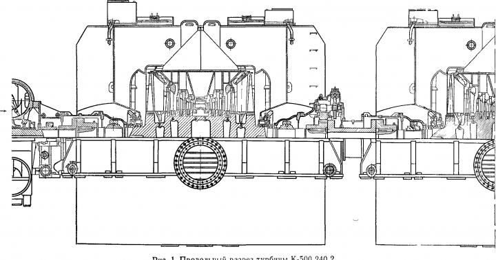
Longitudinal section of the K-500-240 turbine:
Introduction 3
1. Brief characteristics of turbine unit 4
2. Thermal diagram of the installation 7
3. Auxiliary equipment of turbine unit 9
3.1. Capacitor 9
3.2. Low pressure heater (LPH) 11
3.3. High pressure heater (HPH) 14
3.4. Deaerator 15
4. Fuel economy 17
4.1 General layout and equipment of the fuel economy
fuel oil power plants 17
4.2. Characteristics of the fuel used 18
Conclusion 20
Literature 21
Introduction
The goals of this course project are to expand and consolidate knowledge through special courses, mastering the principles of increasing the efficiency of thermal power plants, as well as methods for calculating thermal circuits of steam plants, their individual elements and analyzing the influence of technical decisions made when choosing a thermal circuit and operating factors on the technical and economic indicators of installations.
Electricity production in our country is carried out by thermal power plants - large industrial enterprises in which a disordered form of energy - heat - is converted into an ordered form - electric current. An integral element of a powerful modern power plant is a steam turbine unit, a combination of a steam turbine and its driven electric generator.
Thermal power plants, which, in addition to electricity, supply heat in large quantities, for example, for the needs of industrial production, heating buildings, are called combined heat and power plants (CHP). More than 60% of electricity at thermal power plants is generated on the basis of thermal consumption. Thermal demand operating mode ensures lower losses in the cold source. By using waste heat, CHP plants provide greater fuel savings.
1. Brief characteristics of the K-500-240 turbine unit.
The condensing steam turbine K-500-240 LMZ of the production association of the turbine building "Leningrad Metal Plant Plant" (POT LMZ) with a rated power of 525 MW, with an initial steam pressure of 23.5 MPa is intended to drive an alternating current generator type TVV-500-2EUZ with a power of 500 MW and for operation in a block with a direct-flow boiler. The nominal parameters of the turbine are given in table. 1.1.
Table 1.1. Nominal values of the main parameters of the K-300-240 turbine
The turbine has eight unregulated steam extractions designed to heat the feed water (main condensate) in four HDPEs, a deaerator and three HPHs to a temperature of 276 °C (at the rated turbine load and feeding the drive turbine of the main feed pump with steam from the turbine extractions).
Data on steam extraction for regeneration and turbo drive are given in Table 1.2.
Table 1.2. Characteristics of selections.
The given data correspond to the operating mode at a nominal steam flow through stop valves with a rated power of 525 MW, nominal initial parameters of steam and intermediate superheating steam, a nominal cooling water temperature of 12 °C and its flow rate of 51,480 m3/h, steam flow for auxiliary needs in the amount 35 t/h from the selection behind the 23rd (34th) stages of the central circulation pump and feeding the cycle with demineralized water 33 t/h.
At maximum flow rate, including steam extraction for auxiliary needs behind the CSD and other extractions, except for the regeneration system, without replenishment to the condenser, nominal steam parameters and nominal flow rate and cooling water temperature, a power of 535 MW can be obtained.
The turbine is a single-shaft four-cylinder unit consisting of 1 HPC + 1 CSD + 2 HPC. Steam from the boiler is supplied through two steam lines to two stop valves. Each of them is interlocked with two control valves, from which steam flows through four pipes to the HPC. Four nozzle boxes of branch pipes are welded into the inner housing of the HPC. The steam supply fittings have welded connections to the outer body of the cylinder and movable connections to the necks of the nozzle boxes.
Having passed the nozzle apparatus, the steam enters the left flow, consisting of a control stage and five pressure stages, turns 180° and is transferred to the right flow, consisting of six pressure stages, and is then discharged for intermediate superheating through two steam lines. After intermediate overheating, the steam is supplied through two pipes to two shut-off valves of the CSD, installed on both sides of the cylinder, and from them to four boxes of control valves located directly on the cylinder.
The two-stream DSD has 11 stages in each stream, with the first stages of each stream located in a common internal casing. From the exhaust pipes of the LPC, steam is supplied through two pipes to two LPCs.
LPCs are two-flow, have five stages in each flow. Steam is admitted into the middle part of the cylinder, consisting of outer and inner parts. The LPC exhaust pipes are welded to the longitudinal condenser.
The HP and SD rotors are solid forged, the ID rotors are with mounted disks, with the height of the last stage rotor blades being 960 mm. The average diameter of this stage is 2480 mm. The rotors have rigid couplings and rest on two supports.
The fixed point of the water supply (thrust bearing) is located between the HPC and the CSD.
The turbine is equipped with steam labyrinth seals. The penultimate section of the LPC end seals is supplied with steam with a pressure of 0.101-0.103 MPa from the manifold, the pressure in which is maintained by the regulator at 0.107-0.117 MPa. The HPC and CSD end seals operate on the principle of self-sealing. The suctions from the penultimate compartments are brought together into a common manifold, in which a pressure of 0.118-0.127 MPa is maintained by the regulator “upstream”.
From the end fireplace chambers of the seals of all cylinders, the steam-air mixture is sucked off by an ejector through a vacuum cooler. The power supply circuit for the end seals of the HPC and CSD makes it possible to supply hot steam from an external source when starting the turbine from an uncooled state.
The turbine blade apparatus is designed and configured to operate at a network frequency of 50 Hz, which corresponds to a turbine unit rotor speed of 50 s -1 . Long-term operation of the turbine is allowed with frequency deviations in the network of 49.0-50.5 Hz.
2. Thermal diagram of the installation.
The principal thermal diagram (PTS) of a power plant determines the main content of the technological process of generating electrical and thermal energy. It includes the main and auxiliary heat and power equipment involved in the implementation of this process and is part of the steam-water path.
Having passed the working cylinders of the turbine, the steam enters the condenser unit, which includes a condenser group, an air removal device, condensate and circulation pumps, a circulation system ejector, and water filters.
The condenser group consists of one condenser with a built-in bundle with a total surface area of 15,400 m2 and is designed to condense the steam entering it, create a vacuum in the exhaust pipe of the turbine and preserve the condensate. In order to reduce thermal stresses and prevent uncoupling of the shaft joints, lens compensators are provided on the condenser housings, ensuring compliance of the tube sheets relative to the condenser body.
The air removal device is designed to ensure the normal process of heat exchange in the condenser and other vacuum devices, as well as to quickly build up vacuum when starting a turbine unit and includes two main water-jet ejectors, two water-jet ejectors of the circulation system for removing air from the upper parts of the condenser water chamber and the upper water chambers of oil coolers, as well as water-jet ejector for removing air from the stuffing box heater PS-115.
To remove condensate from the condensate collectors of the condenser and supply it to the block desalting unit, the turbine unit has three 1st stage condensate pumps, and to supply condensate to the deaerator - three condensate pumps, which are driven by AC electric motors.
Circulation pumps are designed to supply cooling water to the condenser and turbine oil coolers, as well as to the generator gas coolers
The regenerative unit is designed to heat feed water with steam taken from unregulated turbine extractions, and has a closed-loop heater for generator gas coolers, a steam cooler for labyrinthine seals, four HDPEs, a deaerator and three HPHs.
HDPE - chamber, vertical, surface type are a structure consisting of a water chamber, a housing and a pipe system
PND3 has a built-in cooler for heating steam condensate, and PND4 is made with a built-in steam cooler, each equipped with a control valve for removing condensate from the heater, controlled by an electronic regulator. HDPE2 is equipped with two control valves, one of which is installed on the pressure line of the drain pumps from HDPE, the other - on the condensate discharge line to the condenser, both are controlled by one electronic regulator.
The turbine has selections for network water heaters to cover district heating needs.
Figure 2.1. Thermal circuit diagram
turbine units K-500-240.
3. Auxiliary equipment of the turbine unit
The thermal design of the installation is largely determined by the regenerative heating of the feedwater. Such heating of water with steam, partially spent in the turbine and removed from it through regenerative extractions to the heaters, increases the thermal efficiency of the cycle and improves the overall efficiency of the installation. The regenerative feedwater heating system includes heaters heated by steam supplied from the turbine, a deaerator, some auxiliary heat exchangers (stuffing box heaters that use the heat of steam from seals, steam condensers of evaporators, ejectors, etc.), as well as transfer pumps (condensate, feed water, drain).
The complete heat exchange equipment of the power unit is presented in Table 3.1.
Table 3.1 – Accessory heat exchange equipment
3.1. Capacitor
A condenser is a device designed to transfer heat from turbine exhaust steam to cooling water. The amount of mechanical energy that can be obtained from 1 kg of steam depends on the initial parameters and pressure at the end of expansion. In this case, the pressure value at the end of expansion affects the performance of a unit mass of steam more than the initial parameters. The expansion of steam in the turbine can only be carried out up to the pressure in the medium into which it then enters. For example, gas expansion in a gas turbine is only possible up to atmospheric pressure. Hence the second purpose of the condenser: to maintain the lowest pressure value at the end of expansion. The rarefaction or vacuum in the condenser is maintained mainly due to the condensation of the steam entering it.
Figure 3.1 – Surface capacitor
The surface condenser consists of a welded or riveted steel body 4, to which tube plates 5 are attached at the ends. Thin brass tubes are strengthened in the tube sheets (most often by flaring). The tubes are arranged in bundles in such a way as to provide the least resistance to the passage of steam. Between individual bundles, partitions are often installed to collect and drain condensate 15 past the underlying bundles, so that excess condensate does not reduce the heat perception of the underlying bundles. The tube bundle is the main structural element of the condenser. The tube bundle is arranged taking into account the fact that in the area close to the steam entrance to the bundle, massive condensation of steam occurs with a very low relative air content, and in the area of suction of the steam-air mixture by the ejector, condensation is much weaker and the falling condensate is strongly supercooled. In order to prevent jets of condensate formed in the zone of mass condensation from entering the zone of increased partial air pressure, the tube bundle is divided into parts: the main bundle and the air cooler bundle. The main task of the main bundle is to ensure mass condensation of steam with low hydraulic resistance, since the lower the hydraulic resistance of the bundle, the lower the pressure in the condenser neck will be.
Short description
The main parts of the condensing steam turbine K-500-240 LMZ, purpose, operating principle of these elements. Principles for increasing the efficiency of thermal power plants. Consideration of methods for calculating thermal circuits of STUs and their individual elements. Analysis of the influence of technical decisions made when choosing a thermal scheme and operating factors on the technical and economic indicators of installations.
Content
Introduction 3
1. Brief characteristics of turbine unit 4
2. Thermal diagram of the installation 7
3. Auxiliary equipment of turbine unit 9
3.1. Capacitor 9
3.2. Low pressure heater (LPH) 11
3.3. High pressure heater (HPH) 14
3.4. Deaerator 15
4. Fuel economy 17
4.1 General layout and equipment of the fuel economy
fuel oil power plants 17
4.2. Characteristics of the fuel used 18
Conclusion 20
Literature 21
manufacturer
pump type and equipment
manufacturer
quantity, pcs.
manufacturer
K-300-240 KhTGZ and LMZ
"Economizer"
Steam turbine OR-12PM
Kaluga Turbine Plant (KTZ)
Sumy Pump Plant
Electric motor AB-8000/6000
Sibelektrotyazhmash
Fluid coupling MGL-7000-2
Gearbox type B -10N
Kazan Compressor Plant
12PD-8 (pre-switched pump)
Electric motor 2AZM-500/6000
K-500-240 KhTGZ
"Economizer"
Steam turbine OK-18PU-500 with gearbox type R-1A
PD-1600-180-1 (upstream pump)
Sumy Pump Plant
Drive via turbine gearbox
K-800-240 LMZ
"Economizer"
Steam turbine OK-18PU-800 with gearbox type R-1A
PD-1600-180 (upstream pump)
Sumy Pump Plant
Drive via turbine gearbox
T-250/300-240 TMZ
PTN-1100-350-24
"Economizer"
Steam turbine
"Economizer"
Sumy Pump Plant
Electric motor AB-8000/6000
Sibelektrotyazhmash
Fluid coupling MGL-7000-2
Gearbox type B-10N
Kazan Compressor Plant
12PD-8 (pre-switched pump)
Sumy Pump Plant
Electric motor 2АЗМ-5000/6000
Feed pumps with a turbo drive are manufactured by the Economizer plant, and with an electric drive - by the Sumy Pump Plant (table).
Each unit with a turbine type K-300-240 or T-250/300-240 is equipped with one working feed pump with a turbo drive and one start-up pump with an electric drive.
Pump types
PTN-1100-350-24
for LMZ blocks
for KhTGZ blocks
Nominal productivity, m 3 / h
Pump shaft power, MW
Number of pump stages, pcs.
Extraction pressure after the first stage, kgf/cm 2
Amount of water taken after the first stage, m 3 /h
Unit dimensions (approximately), mm:
1915
On each unit with a turbine type K-500-240 or K-800-240, two working feed pumps with turbo drives are installed.
Turbo drives for feed pumps of blocks with turbine type T-250/300-240 are manufactured by the Economizer plant, and for feed pumps of blocks with turbines of types K-300-240, K-500-240 and K-800-240 - Kaluga Turbine Plant (Table).
Types of drive turbines/
OK-18PU for block K-800-240
OK-18PU for block K-500-240
"Economizer" plant
Fresh steam pressure before stop valve R ab, kgf/cm 2
Temperature of fresh steam before the stop-control valve, ° C
Exhaust steam pressure R ab, kgf/cm 2
Steam consumption at nominal parameters, t/h
Number of pressure stages
Average blading diameter (maximum), mm
Rated power, kW
15550
12500
Nominal rotation speed, rpm
4650
6000
Capacitor type
KP-1200
Cooling water temperature (nominal), °C
Water flow through the condenser at rated load, m 3 / h
3400
3400
-
Principle of operation
Active
In addition to the pump and electric motor, the set of a feed pump with an electric drive includes a fluid coupling and a gearbox driven by the main electric motor, and an upstream pump driven by an independent electric motor (table).
Motor type
2AZM-500/6000
Rated power, kW
8000
Voltage, V
6000
Nominal rotation speed, rpm
Electric motor weight, kg
Rotor weight, kg
Weight of the heaviest part for installation (stator), kg
Pump types
PD-1600-180-1 for a 500 MW unit
PD-1600-180-1 for 800 MW unit
Flow (nominal), m 3 / h
1000
1630
Pressure in the inlet pipe, kgf/cm 2
Pressure in the pressure pipe, kgf/cm 2
21,0
23,5
22,0
Feedwater temperature, °C
Rotation speed, rpm
1910
1890
2975
Pump shaft power MW
0,545
0,885
0,335
Backwater above liquid vapor pressure, m st. liquid
Efficiency, %
Pump weight, kg
3675
3675
1780
Weight of the embedded frame, kg
Pump dimensions, mm
length
2003
1414
width
1790
1300
height
1515
1000
Unit dimensions, mm:
length
3200
width
1460
height
1095
The set of a feed pump with a turbo drive for blocks of types K-500-240 and K-800-240 includes an upstream pump driven by a turbo drive of the feed pump through a gearbox (table).
Technical characteristics of the equipment of the electric feed pump type PE-600-300-2 are given below.
Fluid coupling MGL-7000-2
Rated transmitted power, kW............................................. 7000
Drive shaft rotation speed, rpm.................................................... .. 2960
Sliding control depth, %:
automatic........................................................ ........................ from 3 to 20
manually................................................. .................................... from 3 to 80
Efficiency at sliding 3%, %............................................... .................... 95
Fluid coupling weight, kg................................................... ........................... 2270
Weight of the embedded frame, kg................................................... ........................ 215
Pump check valve with throttling device and valve D at 50
Conditional diameters, mm:
at the entrance................................................... ........................................... 225
at the exit................................................ ................................... 250
Working pressure, kgf/cm 2 ............................................... ........................... 380
Water flow through throttling device
recirculation, m 3 / h................................................... .................................... 130
Check valve weight, kg................................................... ................... 730
Gearbox B-10N
Transmitted power, kW................................................... ............... 7200
Gear ratio............................................... ........................... 2.2
Input rotation speed, rpm.................................................... .......... 2960
Weight of gearbox with plate, kg.................................................... ................... 3452
Emergency oil tank
Capacity, m 3 ................................................... ................................................... 0, 15
Weight, kg................................................... ........................................................ .143
Air cooler type VPT-108-1000 electric motor type AB-8000/6000
Weight, kg................................................... ........................................................ .315
Data on the mass of feed pumps and drive steam turbines are given in table respectively. And .
| Weight by pump type, kg |
||||
| PTN-1100-350-24 | ||||
| Pump complete with frame | 21050 | 16288 | 16624 | 12080 |
| including: | ||||
| pump housing | 8324 | 6263 | 6263 | 4640 |
| discharge cover | 1900 | 1560 | 1560 | 1500 |
| flow part | 3921 | 2580 | 2588 | 2248 |
| Vertical check valve (without flanges) Venyukovsky valve plant | 1914 | 1914 | 1914 | |
| Sieve assembly | 644 | |||
| including: | ||||
| turbine rotor | 3855 | 3886 | 1578 | 1429 |
| front chair | 2590 | 2590 | 1871 |
|
| back chair | 1834 |
|||
| gear coupling | 284,1 | 162,5 |
||
| turning device | ||||
| turbine stator without cages and diaphragms | 8700 | 8700 | 4500 | 6415 |
| of them: | ||||
| bottom half | 6000 | 6000 | 3500 | 3642 |
| upper half | 2700 | 2700 | 2500 * | 2773 |
| Gearbox | ||||
| Front foundation slab (frame) | 1070 | Feed pumps - centrifugal horizontal two-casing design, with an internal sectional casing, with one-sided arrangement of impellers. The outer casings of the pumps are made of alloy steel forgings. Intake and pressure pipes directed downwards are welded to the outer casing of the pump, a pipe for intermediate selection after I pump stages, four support legs for mounting the pump on the frame. On the discharge side, the outer casing is closed with a lid. A metal sealing gasket is installed between the body and the cover. The cover is attached to the body with studs and blind (cap) nuts. The joints of the body and cover are welded with stainless steel to increase corrosion and erosion resistance. Mounting the pump on the frame allows for its free thermal expansion without disturbing the alignment with the drive shaft. In the front legs (the pair of legs on the suction side) of the pump body there are two transverse keys that guide the expansion of the pump in the longitudinal direction. To prevent To prevent asymmetrical lateral displacements of the pump axis relative to the vertical plane, keys are provided on the suction and discharge pipes of the pump. These keys allow thermal expansion of the housing in the transverse direction. | ||
STEAM TURBINE PLANT K-500-240-2
WITH A POWER OF 500 MW
The condensing single-shaft steam turbine K-500-240-2 (Fig. 1) without controlled steam extraction, with intermediate superheating, rated power of 500 MW, with a rotor speed of 3,000 rpm is designed to directly drive the TGV-500 alternating current generator. The turbine operates in a block with a boiler and is equipped with a regenerative device for heating feed water.
The turbine is designed to operate at the following nominal parameters (Table 1)
The turbine has nine unregulated steam extractions for regenerative heating of feedwater to a temperature of 265° C.
Steam extractions from the turbine for regeneration and turbo drives are shown in Table 2.
The consumption of waste steam into the condenser is 965 t/h.
|
Consumer |
Parameters in the sampling chamber |
Amount of steam taken, t/h |
||
|
Pressure, MPa (kgf/cm2) abs. |
Temperature, °C |
|||
|
Deaerator |
||||
|
Fresh steam in front of automatic HPC shut-off valves: |
||
|
pressure, kgf/cm 2, abs. |
||
|
temperature, °C |
||
|
Steam at the outlet of the HPC at nominal mode: |
||
|
pressure, kgf/cm 2 abs. |
||
|
temperature, С |
||
|
Steam after intermediate superheating in front of the shut-off valves of the CSD: |
||
|
pressure, kgf/cm 2 abs. |
||
|
temperature, °C |
||
|
Main parameters of the capacitor group: |
||
|
cooling water consumption, m 3 /h |
||
|
cooling water temperature, C |
||
|
design pressure, kgf/cm 2 abs. |
||
The main joint venture is fed with steam from extraction VII with a pressure of 0.156 MPa (1.6 kgf/cm2) in an amount of 22 t/h (maximum 32 t/h) abs.
The two main feed pumps have steam turbo drives, the steam for which is taken from the central circulation pump with a nominal pressure of 1.18 MPa (11.2 kgf/cm 2) abs. and a temperature of 374°C in an amount of 98 t/h.
Long-term operation of the turbine is allowed with deviations from the nominal parameters within the following limits: simultaneous pressure deviation of 23-24 MPa (235-245 kgf/cm 2) abs. and temperatures 530-545° C; steam temperature after intermediate overheating 530-545°C (before the shut-off valves of the CSD); when the temperature of the cooling water entering the condensers increases to 33° C.
When the fresh steam temperature in front of the automatic stop valves is in the range of 545-550 ° C, as well as the steam temperature after reheating in front of the CSD stop valves in the range of 545-550 ° C, the turbine is allowed to operate for no more than 30 minutes, and the total duration of operation at these temperatures a couple should not exceed 200 hours per year.

Operation of the turbine to exhaust into the atmosphere and operation according to a temporary unfinished scheme are not allowed.
Long-term operation of the turbine at sliding pressure of fresh steam is allowed in the operating load range from 30 to 100% of the nominal load with the HPC control valves fully or partially open.
Long-term operation of the turbine is not allowed at a load below 150,000 kW at rated parameters of fresh steam with deviations not exceeding the limits specified above.
The turbine unit is equipped with a shaft turning device that rotates the shaft line at a frequency of 4 rpm, and hydraulic lifting of the rotors.
The turbine is flushed during startup from a cold state with saturated steam supplied to the HPC and CSD, as well as at reduced load without stopping the unit in a certain mode agreed upon with the plant.
The turbine blade apparatus is designed and configured to operate at a network frequency from 49 to 50.5 Hz. In emergency situations, short-term operation of the turbine is allowed with an increase in frequency to 51 Hz and a decrease to 46 Hz for the time specified in the technical specifications.
Start-up and subsequent loading of the turbine after a shutdown of any duration is allowed. Automated turbine start-up is provided based on sliding steam parameters from a cold and uncooled state.
Turbine condensers are equipped with water and steam receiving devices. Water intake devices are designed to receive 5000 t/h of water at a pressure of 1.9 MPa (20 kgf/cm 2) abs., at a temperature of up to 200 ° C, from the boiler and ignition expanders when starting a turbine. Steam receiving devices are designed to receive steam from the BROU during load sheds of up to 900 t/h at a pressure of up to 0.97 MPa (10 kgf/cm 2) abs. and a temperature of 200° C. The intake of steam and water into the condensers stops when the pressure in the condensers is above 0.03 MPa (0.3 kgf/cm 2) abs.
The duration of turbine starts from various thermal states (from shock to rated load) is approximately equal to: from a cold state - 6-7 hours; after 48-55 hours of inactivity - 3 hours 30 minutes - 4 hours; after 24-32 hours of inactivity - 2 hours; after 6-8 hours of inactivity - 1 hour; after 2-4 hours of inactivity - 30 minutes.
To reduce the turbine warm-up time and improve start-up conditions, steam heating of the flanges and studs of the horizontal connector of the HPC and CSD is provided.
Turbine design. The turbine (see Fig. 1) is a single-shaft four-cylinder unit consisting of a HPC; CSD and two CND.
Fresh steam from the boiler is supplied through two pipelines to two stop valve boxes installed symmetrically relative to the longitudinal axis of the turbine.
Each stop valve box is interlocked with two control valve boxes, from which steam is supplied to the HPC through four pipes.
The HPC has an internal casing, into the nozzles of which nozzle boxes are welded. Through the nozzle apparatus, steam enters the HPC, the regulating stage, and then into nine pressure stages. The CSD is single-flow, has 11 pressure levels. From the exhaust pipes of the CSD, steam is supplied through four pipes to three low-pressure cylinders.
LPC is two-flow, with five stages in each flow.
The length of the working blade of the last stage is 1050 mm, the average diameter of the impeller of this stage is 2550 mm. The working blades of the last stage have a peripheral bandage. Each LPC is connected to its own capacitor.
ChVD and ChSD rotors are solid forged, LPC rotors are welded and forged. All rotors have rigid couplings and two supports. Each CND has its own fixed point.
The calculated values of the critical rotation speeds of the turbine shafting with the TGV-500 generator are given below.
The turbine is equipped with steam labyrinth seals. From the outermost compartments of the seals, the steam-air mixture is sucked off by an ejector through a vacuum cooler.The power supply circuit for the HPC end seals allows the supply of hot steam from an external source when starting the turbine from a cold state.
Automatic control system. The turbine is equipped with an automatic control system with hydraulic connections and spool-less protection devices. The unevenness of the turbine rotor speed control is 4.5±0.5% of the rated speed.
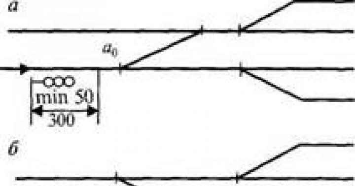
In Fig. Figure 2 shows the control diagram for the K-500-240-2 turbine.
The turbine control system includes an EGP, which reduces the speed overshoot when the generator is disconnected from the network.
The speed regulator controls the position of the control valves of the HPC and the CSD, it is equipped with a power limiter and a control mechanism.
The control mechanism and power limiter can be operated either manually or remotely using reversible DC motors. The power limiter is equipped with a remote position indicator.
Condensate coming from the pressure line of condensate pumps is used as a working fluid in the control system.
To protect against overclocking, the turbine is equipped with a dual safety regulator, which is activated when the rotation speed reaches 11-12% above the nominal one.
The safety circuit breaker actuator causes all shutoff and control valves to close.
Lubrication system designed to provide lubricant (synthetic fire-resistant oil OMTI or mineral oil) to bearings of turbines, generators and a group of feed pumps.
The tank with a capacity of 52 m 3 (up to the upper level) is equipped with: mesh filters to clean the oil from mechanical impurities; air coolers to improve oil deaeration (the air content behind the air cooler should not exceed 1.5%).
To supply oil to the system, two (one backup) AC electric pumps are provided. Two emergency electric pumps are installed: one DC, the other AC.
The oil is cooled in four oil coolers of the MB-190-250 type (one backup), fed with water from the circulation system. The cooling water flow rate for each operating oil cooler is 500 m 3 h. The turbine is equipped with two lubrication pressure switches, which ensure automatic shutdown of the turbine and shaft turning device when the pressure in the lubrication pressure oil line drops, as well as the activation of backup pumps of the lubrication system.
Monitoring and control system the turbine provides: control of operating parameters; registration of the most important parameters; technological, warning and emergency alarms; automatic control of functional groups of technologically related mechanisms and shut-off and control bodies, duplicated by remote control from the control panel; automatic stabilization of a number of parameters, maintaining specified values of which requires surgical intervention during normal operation;

automatic protection of the turbine and auxiliary equipment. The installation is controlled centrally and is carried out from the control panel room.
The monitoring and control system is based on electrical devices and equipment.
Condensing device consists of two condensers, an air removal device, condensate pumps 1 and 2, circulation pumps and water filters.
The condenser group includes two condensers with central air suction. Capacitors - single-flow, two-way.
The air removal device has: two main steam jet ejectors, a steam jet starting ejector of the circulation system and a water jet starting ejector.
The turbine unit is served by two groups of condensate pumps: two 1st lift condensate pumps supplying condensate from the condensers to the desalting unit, and two 2nd lift condensate pumps supplying condensate through regenerative heaters to the deaerator and to the transient control system.
One pump of each group is constantly in operation, the second pump is a backup.
Cooling water is supplied to the condenser by circulation pumps.
To break the vacuum, a DN 150 mm valve with an electric drive is provided. The valve is controlled remotely from the control panel and by three interlocks when the turbine’s unit-wide protections are triggered.
Regenerative plant designed to heat feed water with steam taken from the intermediate stages of the turbine, and consists of five HDPEs, a deaerator and three HPHs. The basic thermal diagram of the installation is shown in Fig. 3.
The scheme provides for the installation of two feed pumps with condensing turbo drives.
HDPE No. 1, 2, 3, 4 and 5 of surface type, vertical, welded structure. HDPE No. 3 and 4 have built-in desuperheaters. The drainage of the heating steam condensate is cascaded, the condensate from the HDPE No. 5 is drained into the HDPE No. 4, from there it is supplied by a drain pump to the main condensate line between the HDPE No. 5 and 4. The condensate from the HDPE No. 3 is drained into the HDPE No. 2, from where it is supplied to the main line by the drain pump condensate between HDPE No. 3 and 2.
At HDPE No. 4 one pump is installed, at HDPE No. 2 there are two drain pumps, one of which is a reserve one.
From HDPE No. 1, condensate is discharged through a siphon into the condenser.
For heating after the feedwater deaerator, two groups of HPH are installed. Three HPHs carry out sequential heating of feedwater after the deaerator.
Each HPH is equipped with a heating steam cooler for the steam superheater, a control valve for removing condensate from the heater and an equalizing vessel for connecting the level regulator sensor with a signaling device.
The group protective device PVD consists of an inlet valve, a check valve, start-up and shutdown pipelines.
Condensate drainage from heaters is cascaded.
When the HPH is turned off, long-term operation of the turbine with a power of up to 500 MW is allowed.