UAZ front pillar
If we consider the design of the UAZ 469 front axle from the point of view of the arrangement of the middle part of the bridge beam, differential and main gear, we can draw an analogy with the rear drive axle. The front axle differs primarily in the design features of the wheel control drive, which includes a gearbox and cardan joints of equal angular velocities (see Fig.). A flange is used to connect the axle housing (1) to the ball joint (3). The hinge body (5) is attached to the support using two pins (4). Gearbox cover (6) is bolted to this housing, on which pin (11) and brake shield (12) are mounted.
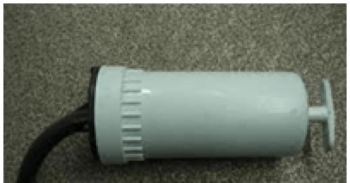
To reduce the wear of the axle elements and fuel consumption while driving on a hard road surface, it is recommended to turn off not only the UAZ front axle, but also the front wheel hubs. For this purpose, the protective caps are removed and the bolts are unscrewed from the shaft hole. As a result, the coupling is installed in such a position that the annular signal groove present on its surface is located in the same plane as the flange end. After the coupling is installed in the desired position, you can begin to tighten the protective cap.
The inclusion of the front wheel is carried out by securely tightening the bolts. The scheme of the bridge device provides for strictly simultaneous switching on and off for both wheels. In order to turn on the UAZ 469 bridge, you must first turn on both wheels without fail.
Repair of the front axle used on a UAZ 469 car requires knowledge of the wheel gear device, the scheme of which is similar to the rear axle wheel gear. The main difference lies in the mounting and fastening of the drive gear, as well as in the design features of the ball bearing installed in a special glass.
About maintenance
Repair and maintenance of the UAZ 469 front axle during operation requires, first of all, periodic checks and adjustments of the following parameters:
- threaded connections that need to be tightened from time to time;
- checking pivot joints for gaps;
- bearing regulation;
- gear clutch repair
- convergence check;
- compliance with the requirements of the lubricant table.
A visual check of the steering knuckles involves a thorough inspection of the assemblies for serviceability of the adjusting bolts, limit stops for turning the wheels and checking the reliability of the locking of these elements. The scheme of the front axle device provides for the maximum angle of rotation of the left and right wheels in the respective directions, which is 28 ° for UAZ 469 and 27 ° for UAZ 469B. A larger value of this parameter causes damage to the knuckle joints, as a result of which the repair becomes much more complicated.

Front strut Patriot
At the factory, the knuckle pins are pre-tensioned. At the same time, the same number of special gaskets are installed from below and from above. During the operation of the bridge, special attention must be paid to the state of the tightening of the pivots. The tightening loosens as a result of wear of rubbing surfaces. Axial gaps appear between the support rings and the ends of the pivots, which must be eliminated by removing the same number of gaskets in the upper and lower parts. The total thickness of the gaskets at the top and bottom should be almost the same, the maximum allowable difference is 0.1 mm.
Unscheduled repair of the front axle may be required if the correct angles of the front wheels are not properly controlled. These angles largely determine not only the handling and stability of the car on the road, but also the degree of tire wear. In order to check the correctness of the angles, the machine is placed on a horizontal surface. The scheme of the leading front axle provides for the following wheel alignment angles:
- longitudinal slope of the pivots - 3 ° ± 30 ′;
- wheel camber - 1°30'±15'.
The values of the angles of the lateral slope of the kingpin:
- for UAZ 469 - 8 °;
- for UAZ 469B - 5°30′.
Wheel alignment is checked depending on how worn the rubber is. In order to adjust the toe-in, the machine is placed on a horizontal surface, the wheels are turned in the direction of forward movement. The convergence value, shown in the photo as the difference between distances A and B, can be from 1.5 to 3 mm. To check and adjust the horizontal toe-in, loosen the left and right-handed lock nuts, and then change the length of the tie rod.
Repair features

Repair of the UAZ front suspension
Before performing work, it is necessary to remove the front axle from the machine and disassemble it. Repair includes washing parts, assessing their condition and suitability for subsequent operation. The crankcase, differential and main gear are repaired in the same way as the elements of the rear axle. In case of deformation of the casing of the axle shaft, the restoration is carried out only in a cold state.
The front axle UAZ 469 is dismantled in the following order.
- Blocks are installed under the rear wheels of the car.
- The tubes of the brake system mounted on the spars are disconnected from the flexible hose connected to the brake mechanisms of the wheels. Unscrew and remove the nuts with which the hoses are attached.
- Remove the nuts holding the lower parts of the shock absorbers.
- Unscrew the bolts with which the cardan shaft is connected to the drive gear flange.
- Disconnect the rod from the bipod and remove the nut on its ball pin.
- Unscrew the nuts securing the stepladders of the front springs, after which the lining, lining and stepladders are dismantled.
- The front part of the UAZ 469 is lifted by the frame.
If the axle is equipped with a spring suspension, steps 1-5 are performed, after which the anti-roll bar is disconnected from the trailing arms, and the transverse link and trailing arms from the corresponding brackets.
The device of the front axle UAZ 469 differs from the rear analogue in some design features. In addition to the bridge beam and differential, the assembly includes equal speeds in the corners and a gearbox. The axle housing is connected to the ball joint with a flange. The hinge body is fixed by means of a pair of pins. The gearbox cover with pin and brake shield is bolted to the frame.
Description
To reduce the degree of wear of the assembly parts, it is recommended to turn off the UAZ 469 front axle when moving on a hard surface, the device of which will be discussed later. You should also deactivate the hubs on the front wheels. To do this, remove the caps and unscrew the bolts from the shaft socket. As a result, the coupling is installed in a position corresponding to the annular groove and the end face of the coupling. After installing this element in the required position, they begin to tighten the protective cap.
The activation of the front wheel is carried out by securely fixing the bolts. The bridge design scheme is focused on the synchronous switching on and off of the drive of both wheels.
The device of the front axle UAZ 469
The crankcase, main gear and differential correspond to the elements of the rear counterpart. In modification 469B, an oil flinger ring and a right-hand thread with the stamp "P" are provided. A ball joint is attached to the axle housing. It is fixed with five bolts. Bushings and pins are pressed into it. In addition, on the support there is a cover for the crankcase of the wheel reduction gear and a steering knuckle housing. A trunnion and a brake shield are attached to the locking element with six bolts.
The pivot appendage of the rotary cam is mounted with an interference fit, the value of which is adjustable from 0.02 to 0.10 mm. To prevent rotation of this element, locking pins are provided in the design. Adjustment of the position is made by means of gaskets installed in the upper part, between the fist lever. In addition, the position can be corrected by installing gaskets in the side and bottom of the part.

Peculiarities
The device of the UAZ 469 front axle, the photo of which is presented above, suggests the presence of an oil seal, which is responsible for retaining lubricant in the housing and protecting the rotary cam from contamination. The element consists of an inner cage, a baffle, a felt pad and an outdoor unit. The seal is attached to the frame with bolts.
Protection against the flow of the lubricant mixture from the crankcase of the main gear to the rotary cam is provided by an internal self-clamping oil seal made of rubber in a metal cage. The lubrication of the upper pivot elements and the ball joint is carried out through special grease fittings. The lower elements are lubricated by a substance coming from the support by gravity.

Hinge
The device of the front axle UAZ 469 includes a hinged system for stabilizing the angular velocity. Its design guarantees the stability of the angular velocity of the driving and accompanying shaft. In this case, the distance and deviation between them do not play a role. The hinge itself consists of a pair of forks, in the curvilinear sockets of which four balls are placed. In the central compartments of these parts there is a fifth mounting ball that serves to center the forks.
The longitudinal movement of the hinge is prevented by a ball bearing and a safety washer. The leading inner fork interacts with the axle shaft of the differential gear. On the edge of the outer driven fork, the main gear of the wheel reduction gear and a roller-type bearing with a lock nut are mounted. The internal engagement of the element occurs by bolting. The driven part aggregates with a shaft on a roller bearing and a bronze bushing located in the middle of the trunnion. At the end of the shaft, a device is provided for deactivating the front wheels of the machine. It consists of a movable coupling, spring, balls and bolts. The outer protrusions of the part are connected to the internal slots of the flange, fixed with bolts on the hub.
Reducer device
469 gear unit is almost identical to the rear axle wheel gear. Among the differences between these elements is the way the drive gear is installed and fastened, as well as the design of the ball bearing placed in a special glass socket. The leading one is mounted on the slots of the driven articulated fork. It is fixed with the bearings by means of a special nut, which opens into the groove of the shaft after tightening.

The support washer is located between the roller bearing and the gear. These parts are not interchangeable with rear gear counterparts. Maintenance for both nodes is the same.
UAZ 469 front axle device: connection diagram
The assembly and connection of the part in question is carried out in the following order:
- The sleeve is inserted into the knuckle trunnion by pressing. It should be flush with the end of the landing nest. Then the sleeve is rotated and adjusted with a special brooch to the required diameter.
- Limiting the movement of the hinge of identical angular longitudinal velocities is provided by washers installed in the trunnion and ball bearing. Their location should be directed with lubrication grooves towards the hinge. The fixing washer is fastened by punching in several places at points evenly distributed around the circumference.
- Replacing the pivot bushings involves pressing them and screwing them up to a diameter of 25 mm, with the possibility of passing through each bushing.
- When installing the hinge, grease is poured into the support.
- The device of the front axle on the UAZ 469 involves adjusting the necessary axial tensions with the help of control inserts, on which the location of the bushings and the ball joint itself depend. At least five spacers are used. The total thickness indicators at the top and bottom should not have a difference of more than 0.1 mm.
- Before assembling the stuffing box, the felt ring is impregnated with warm engine oil.
After assembling the front axle, it is checked on the stand in a static state and under load. This position is created by synchronous braking of the axle shafts. If the assembly is assembled correctly, there will be no increased noise of the assembly, oil leakage in the seals and cuffs, as well as at the junctions.

Maintenance
The device of the UAZ 469 front axle, the diagram of which is given above, provides for a number of preventive and adjustment operations during the operation period. Among them:
- Periodic tightening of threaded connections.
- Check pins for gaps.
- Bearing adjustment.
- Repair of gear clutches.
- Convergence check.
- Regular lubrication of moving parts according to the table of prescriptions for the use of lubricants.
A visual check of the UAZ 469 front axle device provides for an inspection of the steering knuckles for the integrity and suitability of the adjusting screws, restrictive rotary stops, as well as the reliability of the stopper of these elements.
The design scheme of the node under consideration is designed for a maximum angle of rotation of both wheels in the corresponding positions of the order of 27 degrees. An increase in this indicator indicates deformation of the hinged rotary cams, and this significantly complicates the repair.

Adjustment
The device of the front axle UAZ 469, the photo of which is given above, in the factory, involves adjusting the pivot with preload. In this case, the same number of corrective pads are installed in the upper and lower parts of the assembly.
The device of the UAZ 469 front axle kingpin differs in that special attention must be paid to the tightening mode of these elements. Fixation weakens as a result of gradual wear of rubbing parts. Axial gaps appear between the pivot ends and the support rings.
Repair
The front 469, the device of which is discussed above, may sometimes require repair. For repair, you will need to remove the part and disassemble it. This process is carried out as follows:
- Blocks are placed on the rear wheels of the car.
- Nuts and other block fastening systems are unscrewed.
- The rod is unhooked from the bipod, after which the nuts on the shock absorbers and the ball pin are removed.
- The fastening of the front springs with pads is dismantled.
- The front part of the car rises beyond the frame, after which the assembly is dismantled.

The front axle UAZ 469, the device described above, requires professional maintenance. But if you have the appropriate skills, you can manipulate this block on your own.
UAZ bridges are rather capricious units. In a car service, for repairs with a complete disassembly of one bridge, they will take at least 2,000 rubles, plus the cost of spare parts and consumables. Therefore, many jeepers will be interested in learning how to do this work on their own.
The bridges of UAZ vehicles are very sensitive to the relative position of all their parts and assemblies. Access to these units for repair and adjustment is possible only after dismantling the bridge and disconnecting the halves of its crankcase. Consider the process of repair and adjustment using the example of the rear axle, since it begins to demand attention much faster than the front axle. This is due to the fact that UAZ SUVs make most of their mileage on paved roads. In this case, the front axle is disabled and wears out much less than the rear axle. The front axle is adjusted in the same way, only the procedure for removing the axle and disassembling it has some obvious differences.
In the event of a gearbox failure, when it is jammed or the operation is accompanied by loud noise, the need for repair is obvious. In addition, adjustment or repair of bridges may be required after monitoring their condition. In any case, we advise you to check the absence of radial play in the front tapered bearing of the drive gear: you need to shake the flange of the drive gear perpendicular to the axis by hand. Even the slightest play is a reason for adjustment. No backlash in driven gear bearings  is determined by a screwdriver through the drain hole of the axle housing. A signal to check the condition of the gearbox can also serve as a slight noise that increases under load. Perhaps, such a barely audible noise that occurs when driving on an ascent revealed a malfunction, expressed in the appearance of shells on the rollers of the bearings of the driven gear (photo 1).
Of great difficulty, especially on cars that have "tasted" the salt of winter roads, is unscrewing the nuts of the brake pipes, without which the removal and disassembly of the bridge is impossible. Therefore, if disassembly of the bridge is planned, it is first necessary to ensure the free unscrewing of these nuts. Help in this hard work  maybe a special split wrench with a tightening bolt and various lotions: WD-40 preparation, brake fluid and the like. In fairness, it must be admitted that in this case, none of the listed drugs helped, and the mobility of the nuts on the tubes was achieved with the help of the household cleaning drug "Drop" borrowed from the kitchen based on phosphoric acid. If not for him, I would have to buy new tubes.
After the problem with the brake pipes is solved and the necessary tools are assembled, you can begin to remove the rear axle.
We unscrew the four bolts with nuts securing the propeller shaft flange to the drive gear flange (photo 2, item 1), move the shaft aside and fix it.
We raise the rear of the car, for example with two jacks, by the frame so that the wheels come off the floor.  We install additional safety stops. If the car breaks off the jacks, serious injury cannot be avoided!
Under the car we perform the following work. We unscrew the nut of the brake pipe from the brake hose (photo 3, item 1). The hose can be plugged with a suitable plug to reduce brake fluid loss. We unscrew the lower fastening nuts (photo 3, pos. 2) and shift the shock absorbers from the axis.
Attention: after carrying out the operation described below, the bridge will go down!
We unscrew the nuts of the ladders (photo 3, pos. 3). Now the bridge can be rolled out from under the car or, if the wheels have been previously removed, dragged out. Without wheels, it weighs 101 kilograms.
After removing the bridge, taking this opportunity, it is advisable to disassemble and lubricate the leaf springs with graphite or any  other grease. For this:
- unscrew the nut of the tightening bolt passing through the holes in the center of all spring sheets, and remove the bolt;
- unbend the fixing clamps, after which the released sheets will fall down;
- We clean them from dirt and rust. We apply a thin layer of lubricant and assemble the springs.
We proceed to dismantle and repair the bridge. We will need the brake pipe wrench mentioned above, a metal angle with welded pins to fix the drive gear flange, a universal puller, a micrometer, a set of shims for the driven gear bearings, as well as a bottle of brake fluid and 0.85 liters of gear oil (do not fill in the drained from crankcase back). It is advisable to stock up on a set of cardboard spacers for the rear axle or a piece of thin thick cardboard for making such  gaskets (photo 4).
We unscrew ten bolts securing the axle shaft to the hub (photo 5, pos. 1). Screwing the same bolts into the threaded holes on the axle shaft (photo 5, pos. 2) to facilitate removal, remove the axle shafts from the axle housing, trying not to damage the gaskets located between the flange and the hub.
We unscrew the nuts of the brake pipes from the tee and from the brake cylinders (photo 3, pos. 4). In this case, it is necessary to ensure that the nut rotates on the brake tube and does not twist it. We remove the tee from the bracket.
We unscrew the bolts and nuts connecting the halves of the crankcase (photo 2, pos. 2). We disconnect the halves of the crankcase, while trying to save the gasket (it will not be easy to find it later, you will have to make it yourself).
We take out the differential housing assembly with the driven gear.
We take out with the help of a puller the outer rings of the bearings from the halves of the crankcase. If it was not possible to find a suitable puller, you can remove them using a mounting tool (photo 6). At the same time, steps must be taken to  protect the flanges of the crankcase halves at the point of their connection from damage.
If it is necessary to replace the gears of the main pair or differential (including the self-locking one), we unscrew the bolts securing the driven gear to the differential housing. We replace and install the driven gear on the differential housing.
With the help of a puller, we remove the inner rings of the bearings together with separators and rollers from the differential journals (photo 7).
We will return to adjusting the differential bearings later, but for now let's take a look at the drive gear.
The main support of the drive gear is the front double-row tapered roller bearing. The rear ball plays a supporting role. The reliability of the bridge largely depends on the condition of the front bearing. For adjustment, it is necessary to remove the drive gear from the right half of the crankcase. To do this, unscrew the bolts securing the front bearing cover (photo 2, pos. 3), mark the relative position of the cover (it is not symmetrical) and the crankcase (the marks made during disassembly will help you immediately find the desired position during assembly), press out or knock out with a punch from a soft metal rear bearing from its support in the crankcase.
We unpin the flange fastening nut and unscrew it (photo 8, pos. 1). To fix the flange from turning, we use a special key - a strong metal corner of about a meter in length with two pins welded on the end that enter the flange holes.
We remove the bearing cover with the stuffing box, while trying not to damage the cardboard gaskets located between them (photo 8, pos. 2). Using a puller, remove the front bearing from the axle (photo 9).  All disassembled parts and assemblies must be carefully inspected and replaced as unusable.
There are shims between the inner rings of the drive gear bearing (shown by the arrow in photo 10). Using a micrometer, we measure the thickness of all gaskets, remove the thinnest one to create a preload in the bearing, and install the rest back. We press the bearing onto the shaft with a soft alloy hammer. We collect (photo 11), but without a cover with an oil seal. Tightening the nut with a torque of 17-21 kgf, hold the flange with a special key.
We check the resistance to turning the drive shaft in the bearing. A dynamometer, or simply a spring steelyard, fixed to a hole in the flange, should show 1.5-3.0 kgf for worn-in and 2.0-3.5 kgf for new bearings. If turning occurs with less effort, it is also necessary to reduce the total thickness of the shim pack. If turning becomes too tight, the thickness of the shim pack must be increased.
After selecting the required thickness of the gasket package, unscrew the nut, remove the flange and assemble the assembly again, but with the stuffing box cover.
When tightening the flange fastening nut, its reverse rotation to match the holes for the cotter pin must not be allowed, rotate only clockwise (for tightening).
Let's start adjusting the differential bearings. We press the outer rings of the tapered bearings into the halves of the crankcase, and press the inner rings of the bearings onto the necks of the differential box, leaving a gap between them and the box of 3.0-3.5 mm (shown by arrows in photo 12, which shows a self-locking differential without a driven gear).
We install the differential with the driven gear in the axle housing and tighten its halves with bolts, installing a cardboard gasket between them.
Through the hole in the drive gear (it has not yet been installed), we turn the driven gear so that the rollers take the correct position when tightening the bolts.
After tightening the bolts, unscrew them again and disconnect the crankcase halves.
We take out the differential and measure the resulting gaps between the ends of the differential housing and the inner rings of the bearings on both sides.
The sum of these gaps, plus 0.1 mm, indicates the required total thickness of the shims installed on both sides. Let's look at an example. The gap on the left was 1.0 mm, on the right - 2.5 mm, then the total thickness of the gaskets should be 3.6 mm.
We remove the inner rings of the bearings from the necks of the differential, put shims on the necks, aligning the cuts for the puller on them from the outside. In our example, spacers with a total thickness of 1.8 mm must be installed on each side. We press the inner rings of the bearings onto the necks of the differential housing. We install the drive gear assembly with bearings in the right half of the crankcase.
When installing the drive shaft in the rear axle housing, it must be taken into account that the rectangular cutouts on the inner edges of the cardboard spacers and the hole in the housing for grease access to the bearings must  coincide. If during disassembly some of the cardboard spacers are torn, their total thickness must be restored.
We connect the halves of the crankcase together with the differential and check the play in the engagement of the gears of the main pair. When measured on the outer edge of the drive gear flange, it should be 0.35-0.77 mm. If the gap is larger, smaller or missing, you will have to rearrange the shims from one side of the differential to the other.
To do this, we disconnect the halves of the axle housing, take out the differential and remove the inner bearing rings from it with a puller. To reduce the gap, we reduce the thickness of the gaskets on the side of the teeth of the driven gear and vice versa. Let's say we need to reduce the gap. Let's rearrange the gasket with a thickness of 0.2 mm. Then the total thickness of the spacers on the side of the teeth will be 1.6 mm, and on the opposite side 2.0 mm.
We tighten the crankcase halves and again check the clearance. If necessary, adjust the clearance again. To the touch, it appears as barely perceptible.
Bridges without final drives are not subject to checking and adjusting the meshing in the teeth of the main gear gears along the contact patch.
We complete the assembly of the bridge in the reverse order and install it on the car, while lubricating the threads of the bolts and nuts, discarding the unusable ones.
Pour 0.85 liters of gear oil into the crankcase of the bridge.
We bring the bridge under the springs and fix it with stepladders. We lay the brake pipes on the outside of the ladders.
We put the lower lugs of the shock absorbers on the axis of the bracket and fix them with nuts.
We screw the nuts of the brake pipe into the upper end of the brake hose.  Using four bolts with nuts, we connect the flanges of the drive gear of the gearbox and the cardan shaft.
We pump the brakes.
This work is completed. If any parts of the gearbox have been replaced, a gentle operation is required to run them in. For at least a few hundred kilometers, high speed driving should be avoided. Ideally, the break-in regime of a new car should be observed. But, what is especially important, you should sometimes stop and test the temperature of the rear axle crankcase in the area of \u200b\u200bthe gearbox with your hand. It is good if the hand calmly withstands heat, but temperatures up to 90 ° C are considered acceptable. If the temperature is higher, this is a sign of improper adjustment. In this case, you can reassure yourself that the repeated procedure for disassembling the bridge will be easier, since all the stubborn nuts and bolts are lubricated and will turn away easier than the first time.


AUTOMOBILIST'S TOOLS (NORMAL AND WINTER)
Having a full set of tools "on board" the car is a must. Agree, it’s a shame to stand on a deserted road due to some minor malfunction that could be fixed with, for example, an elementary Phillips screwdriver that is not in the tool bag.
When buying almost any Russian car, both used and new, a revision of the toolkit is simply necessary. It is mandatory to complete the tool bag. A complete set of tools for a new car is a rarity. You don't have to go far: when buying a new Volga GAZ-3110 in the spring, I missed more than five positions in the tool bag and - for dessert - a jack and a tire pump! The other day a friend bought a Gazelle Farmer from one of the major GAZ dealers in Nizhny Novgorod - there is no tool at all!
However, even fully equipped with a standard tool, it is not recommended to feel calm and secure. It is highly desirable to be understaffed. Here the other extreme is dangerous. There are those who like to carry with them a lot of unnecessary things, among which the necessary things may not be.
Based on my personal year-round experience of intensive operation of VAZ ("classic") cars, I can recommend the following set of running spare parts and additional tools for equipping a car, which once turned out to be extremely necessary in critical situations.
1. Movable contact of the breaker-distributor (slider) (1 pc.).
2. Cover of the breaker-distributor (1 pc.).
3. Rotor breaker-distributor (1 pc.).
4. Spark plugs (2 pcs.).
5. Spark plug tip (1 pc.).
6. High-voltage wire (cut) or one long wire for the 4th cylinder (1 meter).
7. Built-in voltage regulator with brush assembly, assembled or separately (1 pc.).
8. Ignition coil (1 pc.).
9. Rotor resistor (1 pc.).
10. Capacitor for the breaker-distributor (1 pc.).
11. Fan (generator) belt (1 pc.).
12. Gasoline pump diaphragm assembly (1 pc.).
13. Working brake cylinder or cuff of the working brake cylinder (2 pcs.).
14. Outer bearing of the front wheel hub (1 pc.).
15. Coupling spring for brake pads (1 pc.).
16. Shock absorber bush (1 pc.)
17. Ball joint upper and lower (1 pc. each).
18. Raw rubber.
19. Rubber material for patches and adhesive.
20. 12 V electric vulcanizer.
21. Brake fluid (400 ml).
22. Grease "Litol-24" (200 g).
23. Control light with wires (probe).
24. Wrench for fittings of pipelines, valves for air release (1 pc.).
25. Powerful awl for installing brake shoe coupling springs (1 pc.).
26. Indicator for checking the operability of the high-voltage circuit of the ignition system (1 pc.).
27. Fuses of the electrical system for 16 and 8 amperes (4 pcs.).
28. Can of WD-40 (1 pc.).
In addition to all of the above, it is useful to have various home-made devices for car repairs on the road, according to numerous tips from experienced motorists. Materials about this are systematically published on the pages of the Birzha plus Avto newspaper.
Winter is coming with its own characteristics of operation, and the "on-board" toolkit of the car must be supplemented. Again, arm yourself with tips for winter operation, and on the road, with little or no increase in the weight of the car, it is recommended to take winter gadgets with you. We will talk about autochemical preparations, which are the most effective for the tasks set and are currently readily available.
1. Silicone grease for rubber seals. Prevents freezing of doors, which is especially important after a thaw or after visiting a car wash.
2. Means for defrosting windows and locks (no comment needed).
3. Aerosols that give glass water-repellent and anti-fog properties. A transparent super-slippery film that appears on the glass after treatment with the drug significantly improves visibility in snowfalls.
4. Aerosol that restores the elasticity of tension belts. The belts "hardened" in the cold not only squeal disgustingly, but also slip on the pulleys. The drug will prevent this.
5. Spray with insulating paint for the ignition system. Sprayed with this agent, the breaker-distributor (distributor), high-voltage wires and the ignition coil will "hold" the spark much more reliably. However, the already recommended WD-40 preparation is also suitable for these purposes.
6. A bottle of moisture neutralizer for fuel systems. There is enough water in the gasoline, and the catalytic converter will prevent the fuel lines from freezing and clogging. For these purposes, the author has been using the preparation "Aspect-modifier. Anti-ice" with great success for a number of years.
For successful winter operation of cars, readers need to carefully monitor the relevant information on the pages of our newspaper.
Front axle of UAZ-452
Device
The front drive axle is designed to transfer traction to the front steered wheels. The main gear and differential installed in the front axle are the same as those of the rear axle. The axis of the drive gear is shifted to the right of the longitudinal axis of the vehicle by 190 mm.
To transfer force to the wheels, constant velocity joints are installed at the outer ends of the axle shafts, which ensure the same rotation speeds of the driving and driven forks at any angle of rotation of the wheels.
The hinge is located inside the pivot pin, the design of which is shown in fig. 2.

Rice. 1. Hinge of equal angular velocities: 1 - driven fork; 2 - leading fork; 3 - central ball; 4 - leading balls; 5 - hinge assembly
The stub axle assembly, with the help of which the wheel is turned, consists of a ball bearing bolted to the axle housing flange, a stub axle housing connected to the ball joint by means of double pins, and a swivel pin. A brake shield is installed on the body of the pivot pin.

Rice. 2. Steering pin: 1- leading fork; 2 - ball bearing; 3 and 17 - adjusting shims of pivots; 4- king pin: 5 - steering trapezoid lever; 6 - body of the pivot pin; 7-1 driven fork; 8 - pivot pin; 9-wheel hub; 10 - leading flange of the hub; 11 - clutch; 12 - fixing ball; 13 - protective cap; 14 - bolt; 15 - splined end of the driven fork; 16 - kingpin pad; 18 - thrust washers of the hinge of equal angular velocities: 19 - casing of the axle shaft; 20 - stuffing box
Pivot bearings are assembled with a preload, which is adjusted by adjusting shims with a thickness of 0.1; 0.15 and 0.4 mm. Gaskets are installed at the top - between the ends of the steering trapezium lever (on the left pivot pin) or lining (on the right) and the pivot pin body and below - between the ends of the lining and the pivot pin housing. The value of the preload in the bearings should be in the range of 0.02-0.10 mm.
During operation, due to wear of the rubbing surfaces of these parts, the preload in the bearings disappears and a gap is formed in them, which adversely affects the durability of the bearings, which is eliminated by adjustment.
To reduce wear of the front axle parts and save fuel during long-term operation of the vehicle on paved roads, it is recommended to turn off the front drive wheels.
For this purpose, a movable coupling is installed in the front axle on the splines of the driven fork, the outer splines of which are engaged with the splines of the leading flange of the front hub.

Rice. 3. Clutch position when turning on and off the front wheels
To disengage the wheels, the clutch must be disengaged from the drive flange.
To do this, it is necessary to remove the protective cap and, unscrewing the bolt from the driven fork, set the coupling to a position where the signal annular groove A on its surface is located in the same plane as the flange end. The bolt is kept from spontaneous rotation by a fixing ball and a spring. Turn on the wheels by screwing the bolt into the fork until it stops.
It must be remembered that the inclusion of the front axle with the wheels off is not allowed.
The front and rear axles have the same final drive and differential, so all instructions for adjusting the pinion bearings, backlash and contact in the final drive gears and rear axle differential bearings apply to the front axle as well.
Maintenance
Maintenance of the front axle consists in performing the same operations that are indicated for servicing the rear axle.
In addition, the following must be done.
At TO-1, lubricate the kingpins of the pivot pins through the grease fitting of the upper kingpin.
With TO-2, remove the front wheel hubs and, shaking the trunnion up and down, determine the presence of play in the pivot pins. If there is a gap, make adjustments. The adjustment procedure is listed at the end of the section.
Check the fastening of the steering trapezium levers to the pivot pins.
Check the maximum steering angles of the front wheels (minimum turning radii).
Through TO-2, perform all the operations indicated for TO-2, but instead of adding grease, rinse the hinges and put 300 g of fresh grease into them.
To replace the grease in the joints, unscrew the bolts securing the wheel trunnion to the body of the swivel pin, remove the brake and the trunnion (do not disconnect the hydraulic brake flexible hose), remove the hinge from the ball joint, remove the old grease, flush the hinge and ball joint and put 300 g of fresh grease. Reinstall the pivot yoke carefully so as not to damage the oil seal in the ball joint.
Front axle faults related to the operation of the final drive and differential gears will be the same as those of the rear axle and are listed in the "Rear axle faults" section.
Removal and disassembly of the front axle
For repair, it is necessary to remove the front drive axle from the car and disassemble it.
After disassembling and washing the parts, you need to check their condition (wear) and determine suitability for further work. Worn parts are replaced with new ones.
To remove the front axle from the car, you should:
- disconnect the pipelines of the hydraulic brake drive, shock absorbers, cardan shaft, steering arm, springs;
- roll back the front axle and install it on a stand or stands.
Disassembly of the front axle is performed in the following sequence.
Remove wheels and brake drums.
Remove the protective cap from the hub drive flange.
Unscrew the bolt from the driven fork and remove the sliding sleeve of the drive flange of the hub.
Unscrew the nuts of the studs securing the drive flange of the front wheel hub. Screw in the two bolts mounted on the flange and remove the flange from the splined end of the driven yoke.
Remove the front wheel hubs.
Remove the brake discs and stub axles and take out the constant velocity joints.
Remove the steering trapezoid arm and kingpin linings with shim sets.
Loosen the ball head nuts and remove the tie rod.
To disassemble the pivot pin, you must:
— to turn away bolts of fastening of an epiploon of a spherical support;
- press out the pivots and remove the stub axle housing;
- in case of wear of the stuffing box installed in the ball joint, you need to unscrew the bolts, remove the ball joint, press out the stuffing box and replace it with a new one.
Disassembly of the front axle housing, final drive pinion shaft and differential, as well as adjustment of the double tapered bearing of the final drive pinion shaft, differential bearings, adjustment of backlash and contact in the engagement of the final drive gears must be carried out in accordance with the instructions made for these units in "Rear Axle" section.
The hinges of equal angular speeds are disassembled in the following order.
Mark with paint the relative position of the driven and driving forks.
Clamp the drive fork in a horizontal position.
Having turned the central ball with the flat towards one of the driving balls, move the driven fork to the side and remove the ball (passing by the flat).
Remove the other three balls in the same way.
Assemble the hinges in the following order.
Clamp the drive fork in a vertical position.
Install the center ball in the spherical recess of the drive fork with the flat to the side.
Place the driven fork on the center ball.
Turning the driven fork to the side, install the three drive balls into the grooves.
Open the forks to the maximum angle and, turning the central ball flat towards the fourth groove, insert the last (fourth) ball that will pass the flat of the central ball.
The preload in the hinge between the balls should be such that the moment required to rotate one fork from 10-15 ° in all directions from the axis with the other fork clamped in a vice is 300-500 kgcm.
To ensure correct assembly and obtain the required preload, the balls are sorted into 9 groups. Each hinge is assembled with balls of one group or with balls of two adjacent groups, for example, two balls of 25.41 mm and two of 25.44 mm.
When mounting, balls of the same size must be placed diametrically opposite to one another.
The difference in the diameters of two pairs of balls of one hinge is allowed no more than 0.04 mm.
If there is a stand, run the hinge on it at a varying angle from 0 to 30 ° for 2 minutes at a rotation speed of 300 rpm.
When running in, lubricate the joint with grease for pivot pins.
Front axle assembly
The front axle must be assembled in the reverse order of disassembly. All instructions for assembling the rear axle also apply to assembling the front axle. In addition to these guidelines, the following must be observed.
Press the bushing into the pivot pin flush with the end face of the socket under the thrust washer.
The oil grooves of the thrust washer mounted on the neck of the stub axle must face outward (toward the yoke flange).
The seating surface of the pivot pin must be lubricated with a thin layer of red lead, shellac or UN-25 sealing paste.
Lubricate the pivots with a liquid lubricant before assembling.
When installing the hinge, put the lubricant indicated in the lubrication chart into the ball joint and the hinge.
Lubricate the sliding sleeve of the drive flange of the hub when installing on the driven fork with a thin layer of grease 1-13 to protect against corrosion.
Lubricate the pivot bearings through the grease nipples with grease "C" or grease "C".
The oil slinger ring of the oil seal of the front axle drive gear, installed between the flange and the inner ring of the bearing, has grooves on the end face with the right turn direction and is marked with the letter "P".
The oil ring installed in the rear axle is left-hand grooved and unmarked. Oil stripping rings must not be interchanged, otherwise oil may leak from the stuffing box.
After completing the assembly of the front axle, it is necessary to check the angles of rotation of the trunnions in each direction and the setting of the toe-in.
The front axle after assembly is checked on the stand under load and without it.
A properly assembled front axle during operation should not have increased noise, heating and oil leakage through the stuffing box, covers and bolted connections.
The procedure for adjusting the pivot pin bearings is as follows.
Raise the front axle with a jack.
Loosen the wheel nuts and remove the wheel.
Loosen the bolts securing the ball joint seal and remove the seal.
Check for axial play at the pivots by moving the stub axle housing up and down by hand. If there is play, adjust, for which:
unscrew the fastening nuts and remove the lever to the bipod rod on the left pivot pin, and the kingpin pad (top) on the right pivot pin, remove the thin (0.1 mm) adjusting shim and install the removed parts in place.
Loosen the mounting bolts and remove the kingpin pad (bottom), remove the thin (0.1 mm) adjusting shim and install the kingpin pad in place.
To maintain the coaxiality of the cardan, gaskets of the same thickness should be removed from above and below.
Check build results. If the play is not eliminated, re-adjust by removing the thicker gasket (0.15 mm) and reinstalling the thin one (0.1 mm).
It is widely used not only in the territory of the Russian Federation, but also abroad. The UAZ loaf front axle device allows you to connect all-wheel drive to overcome off-road. Thanks to this, the machine is distinguished by high cross-country ability in difficult areas of rough terrain.
How the UAZ front axle works
The scheme of the front axle UAZ loaf allows you to determine that it consists of several nodes:
- Composite crankcase;
- Reducer;
- Half shafts.
Below is the arrangement of the components of the front axle of a UAZ loaf car.
Carter
The crankcase of the bridge of the UAZ car loaf consists of 2 parts. Between themselves, the parts are bolted, while forming the gearbox housing. Parts of the crankcase are equipped with mounts for installing springs and shock absorbers.
IMPORTANT: When using the vehicle, the grease in the crankcase heats up and expands. In this case, the pressure in the crankcase cavity increases. To prevent leakage of the crankcase of the bridge, a breather valve is provided. It is installed on the housing of the semi-axis of the UAZ front axle and is necessary for communicating the crankcase cavity with the atmosphere.
Rotary mechanisms are located along the edges of the bridge. They are essential for driving. The mechanisms are pivotally connected to the edges of the crankcase. Pins are installed on the rotary mechanisms. They are necessary for articulated connection with the hubs of the car. To reduce the degree of friction, the hub is mounted on roller bearings.
Reducer
The front axle reducer UAZ loaf consists of the main gear and the cross-axle differential. When the front axle of the UAZ loaf is turned on, the torque from the gearbox is supplied through the cardan shaft to the gearbox flange. It is mounted on the same shaft as the final drive gear.

As the drive gear rotates, it transmits torque to the driven gear. Compared to the drive gear, it has a large diameter. This allows you to reduce the torque transmitted from the transfer case.
REFERENCE: The gear teeth of the main gear of the UAZ car reducer are located at an angle. This prevents the gear teeth from beating against each other, thereby reducing the noise level when the vehicle is moving.
An interwheel differential is located inside the driven gear. It consists of conical satellites and their axes. The differential mechanism includes the splines of the semi-axes. The differential allows you to achieve a difference in the speed of rotation of the wheels of one axle when turning the car. You can also read about.
half shafts
The front axle of the UAZ loaf car is a shaft with slots on the edges. On the one hand, splines are installed in the differential of the gearbox. The other side of the axle shaft drives the wheel hub. The transmission of torque from the front axle gearbox to the wheel mechanism is carried out using a CV joint. It allows you to transmit torque regardless of the angle of rotation of the wheel mechanisms.
A distinctive feature of the front axle of the UAZ loaf car is the ability to disconnect the wheel hubs from the axle shafts. This is necessary to prevent wear on the rotating parts of the gearbox when driving for a long time on a good quality surface.
Possible bridge malfunctions and their causes
The front axle of the UAZ loaf car is distinguished by reliability and unpretentiousness to operating conditions. The most common faults are:
- Violation of the sealing of the crankcase. The excess pressure that occurs when the oil is heated when the car is moving leads to a violation of the sealing of the crankcase. To prevent malfunction, it is necessary to regularly check the performance of the breathing valve;
- Bearings worn out. Occurs as a result of improper operation of the front axle of the UAZ loaf car. Switching the UAZ loaf front axle to the on position when driving on a good quality surface leads to rapid wear of the gearbox bearings. To prevent damage to the bearings, it is necessary to connect the front axle only to overcome off-road;
- Increased wear on rotating parts. Occurs due to poor quality lubricant. It is necessary to change the oil in the front axle regularly. The cause of the malfunction may be water entering the gearbox housing when overcoming the ford. To prevent water from entering the gearbox crankcase, the breathing valve is equipped with a hose attached under the engine compartment cover.

- Violation of the cross-axle differential. Often occurs due to wear of the pivots. To prevent breakage, it is necessary to regularly inspect the mechanism of the pivots for the presence of play. If the permissible values are exceeded, the pivots should be replaced;
- Breakage of the main gear shaft bearing. Occurs due to a malfunction of the propeller shaft cross. The integrity of the cross should be checked regularly.
- High degree of wear of conical satellites or their axes. The integrity of the conical satellites and their axles is affected by the pressure difference in the tires of the front axle wheels. Tire pressure must be constantly monitored to avoid breakdowns.
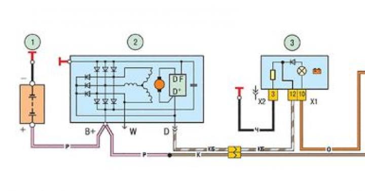
Wiring diagram of the front axle UAZ loaf
Some car owners are wondering how the front axle on the UAZ loaf is turned on? The front axle is engaged in two ways:
- Lever mounted in the cab. The lever controls the transfer case. When the front axle of the UAZ loaf is turned on, using a lever installed in the cabin, the torque from the transfer case is transmitted along the driveshaft to the drive axle.
- With the help of couplings installed in the wheel mechanisms. It is possible to detach the drive axle hub from the axle shaft. Turning the UAZ loaf front axle on and off with the help of clutches allows you to reduce the load on the gearbox when driving on a hard surface.

IMPORTANT: after disconnecting the couplings located in the wheel mechanisms, connecting the all-wheel drive with a lever from the passenger compartment will be impossible.
To engage the clutch it is necessary to remove the protective cover of the drive axle hub. Using a hexagon, tighten the coupling cap until it stops. The axle shaft splines will engage and the hub will be connected to the gearbox. To disengage the clutch, reverse the procedure.
To connect the all-wheel drive with a lever installed in the passenger compartment, it is necessary as follows:
- Disengage the clutch;
- Set the gearshift lever to neutral position;
- Move the control lever to the extreme forward position;
- After completing the steps, the four-wheel drive will be turned on. It is necessary to turn off the four-wheel drive by moving the lever to the rearmost position.
ATTENTION: Before you disable or enable the front axle on the UAZ loaf, you must turn off the clutch. To do this, depress the clutch pedal located in the passenger compartment.
Removal and repair of the front axle
The front axle UAZ loaf has a simple device, which allows you to do the repair yourself with minimal technical knowledge. To remove the assembly from the car, you must:
- Car to a viewing hole, overpass or lift;
- Immobilize the machine to prevent spontaneous rolling. To do this, install recoil devices (shoes) under the rear wheels;
- Jack up the car frame. To simultaneously raise both sides, the jack is installed in the front of the frame in the center;
- To avoid injury, install the car frame on specialized supports;
- Unscrew the nuts securing the axle to the semi-elliptical springs;
- Dismantle the steering arm;
- Unscrew the shock absorber mounting nuts;
- Dismantle shock absorbers;
- Remove the vehicle's drive axle.

REFERENCE: If it is necessary to replace the elastic cushions installed in the spring mounting brackets, the axle is dismantled together with the springs. To do this, instead of the nuts of the ladders, the bolts fixing the covers of the brackets are unscrewed.
A person who has certain skills in repairing equipment can repair and adjust the front axle of a UAZ loaf car. To diagnose a malfunction, it is necessary to conduct a visual inspection of the assembly. From the outside, the UAZ crankcase is inspected for oil leaks. The presence of oil streaks indicates crankcase depressurization. To eliminate oil leakage, it is necessary to replace gaskets and seals. During installation, the gaskets are lubricated with sealant.
After disassembling the assembly, it is necessary to pay attention to the integrity of the bearings. Damaged parts must be replaced with new ones. Particular attention is paid to the wear of rotating parts. If the permissible norm is exceeded, worn parts should be replaced.
ATTENTION: The drive and driven gears of the final drive of the reducer are replaced at the same time. Replacing one of the final drive gears can lead to its rapid wear due to damaged teeth of the second gear.
From the above, it follows that the UAZ front axle, due to its design, improves the technical characteristics of the car. The front axle is equipped with swivel mechanisms. This allows you to transfer torque from the gearbox to the wheels of the vehicle, regardless of their angle of rotation. It is possible to disconnect the gearbox and wheel mechanisms by disengaging the clutches.