In order to create a Tesla generator yourself, you need to have the following parts:
- capacitor;
- arrester;
- the primary coil, which should have low inductance;
- the secondary coil must have high inductance;
- the capacitor is secondary and must have a small capacity;
- wire of different diameters;
- several tubes made of plastic or cardboard;
- regular ballpoint pen;
- foil;
- metal ring;
- pin to ground the device;
- a metal pin to catch the charge;
Step-by-step assembly instructions

In order for the invention to work properly and not pose a threat, you need to carefully follow all instructions and be very careful.
Follow the guide carefully and you won't have any problems:
- Select a suitable transformer. It determines the size of the coil you can make. You need one that can output at least 5-15 watts, and a current of 30-100 milliamps.
- First capacitor. It can be created using smaller capacitors connected like a chain. They will evenly accumulate energy in your primary circuit. But for this they must be the same. The capacitor can be removed from a non-working TV, bought in a store, or made yourself using regular film and aluminum foil. For your capacitor to be as powerful as possible, it must be charged constantly. The charge must be applied every second 120 times.
- Arrester. For a single arrester, you can take a wire whose thickness is more than 6 millimeters. This is necessary so that the electrodes can withstand the heat that will be released. The electrodes can be cooled using a flow of cold air, using a hair dryer, vacuum cleaner, or air conditioner.
- Winding of the first coil. You need a special shape to wrap the copper wire around. You can take it from an old unnecessary electrical appliance or buy a new one in a store. The shape on which the wire will be wound should be either a cylinder or a cone. The inductance of the coil directly depends on the length of the wire. And the primary, as already written above, should be with low induction. There should be few turns, and the wire may not be solid; sometimes pieces are used to fasten them together.
- You can now assemble the created devices into one whole, connecting them one to another, like links in a chain. If everything is done correctly, then they should create a primary oscillatory circuit that the electrodes will transmit.
- Secondary coil. It is created in the same way as the first one, wire is wound around the form, there should be more turns. After all, the second coil is needed much larger and higher than the first. It should not create a secondary circuit, the presence of which could lead to combustion of the primary coil. Do not forget that these coils must be of the same frequency in order to work properly and not burn out when the device is turned on.
- Another capacitor. Its shape can be either round or spherical. This is done in the same way as for the primary coil.
- Compound. To create a secondary circuit, you need to connect the remaining coil and capacitor into one. But, it is necessary to ground the circuit so as not to harm the devices that are connected to the network. You need to ground as far as possible from the wiring that is located throughout the house. Grounding is very simple - you just need to stick a pin into the ground.
- Throttle. It is necessary to make a choke so as not to damage the entire electrical network with the arrester. It’s easy to create – wrap the wire tightly around a ballpoint pen.
- Put it all together:
- primary and secondary coils;
- transformer;
- chokes;
- Both coils need to be placed nearby and connect a transformer to them using chokes. If the second coil turns out to be larger than the first, then the first one can be placed inside.
The device will start working after connecting the transformer.
Device
This device consists of several parts:
- 2 different coils: primary and secondary;
- arrester;
- capacitor;
- toroid;
- terminal;
Also, the primary composition includes a wire with a diameter of more than 6 millimeters and a copper tube. Most often, it is created horizontally, but it can also be vertical and in the shape of a cone. For the other coil, much more wire is used, the diameter of which is smaller than that of the first.
To create a Tesla transformer, they do not use a ferromagnetic core, and thus reduce the induction between the primary and secondary coils. If you use a ferromagnetic core, then the mutual induction will be much stronger. And this is not suitable for the creation and normal functioning of the Tesla device.
The oscillatory circuit is formed thanks to the first coil and the capacitor connected to it. Also, it includes one nonlinear element, namely a conventional gas spark gap.
The secondary one forms the same circuit, but instead of condensate, the capacitance of the toroid and the interturn gap itself in the coil are used. In addition, in order to prevent electrical breakdown, such a coil is coated with special protection - epoxy resin.
The terminal is usually used in the form of a disk, but it can also be made in the form of a sphere. It is necessary to obtain long discharges from sparks.
This device uses 2 oscillating circuits, which distinguishes this invention from all other transformers, which consist of only one. In order for this transformer to work properly, these circuits must have the same frequency.
Principle of operation

The coils you created have an oscillating circuit. If voltage is applied to the first coil, it will create its own magnetic field. With its help, energy is transferred from one coil to another.
The secondary coil creates, together with the capacitance, the same circuit that is capable of accumulating the energy transferred by the primary. Everything works according to a simple scheme - the more energy the first coil is capable of transmitting, and the second one is able to accumulate, the greater the voltage will be. And the result will be more spectacular.
As mentioned above, in order for the device to start working, it must be connected to the supply transformer. In order to direct the discharges produced by the Tesla generator, you need to place a metal object nearby. But do this so that they do not touch. If you put a light bulb next to it, it will glow. But only if there is enough voltage.
To make a Tesla invention yourself, you need to do mathematical calculations, so you need to have experience. Or find an engineer who can help you derive the formulas correctly.
- If you have no experience, then it’s better not to start the work yourself. An engineer can help you.
- Be very careful, because the discharges produced by the Tesla generator can burn.
- Such an invention can damage all connected devices; it would be better to remove them away before turning them on.
- All metal objects, which are close to the switched on device, can burn.
Content:
A noticeable impetus in the development of electrical engineering occurred in the first years of the twentieth century, at which time society and industry evaluated innovative proposals from inventors. According to experts, many ideas can develop for several decades and even a hundred years. History keeps many secrets, including the innovative ideas and projects of Nikola Tesla - this name has become a mystery for many generations of people.
One of Tesla's famous inventions is the transformer he created, more often it is described as a Tesla coil (CT). A demonstration of its operation leaves no one indifferent; you can visually see electrical discharges that can have great significance. The simplicity of the design and the result obtained always make you want to make a similar coil yourself.
Tesla's resonant transformer, which in demonstration mode can show what manipulations with electricity and what techniques the inventor had at that time, has so far baffled traditional science.
The Nikola Tesla coil is a device that produces high-frequency currents. It is implemented using a primary and secondary winding, but the primary winding receives power at the resonance frequency of the secondary winding, and the output voltage increases tens of times.

Tesla patented this invention in 1896, which consists of the following elements:
- the primary winding is made of copper wire with a cross-section of at least 6 square millimeters, which is made in the form of 6–7 turns;
- the winding is secondary, it is implemented on a dielectric with a wire of 0.3 millimeters square and up to 800–1000 turns;
- discharge device;
- capacity (capacitor);
- spark radiation element.
The main difference between KT and all other transformers is that Nikola Tesla did not use ferrite alloys for the core in his invention, and the power of the resulting device depends only on the electrical permeability of air. The meaning of the idea is the creation of an oscillatory circuit, which can be done using several techniques:
- using frequency oscillations - this is a generator implemented on a discharge element;
- using lamps - an oscillation generator;
- using elements of radio engineering - transistors.
Purpose of the invention
According to experts, Tesla invented the transformer to solve the global issue of transmitting electrical energy from one point to another without the use of wires. In order to achieve the transmission of energy conceived by the inventor using the ether, it is necessary to have one powerful transformer at two remote points, which would operate at the same frequency in resonance.
If the project is implemented, then there will be no need for hydroelectric power stations, powerful power lines, or cable lines, which, of course, contradicts the monopoly ownership of electrical energy by different companies. With Nikola Tesla's project, every citizen of society could use electricity for free at the right time, anywhere, wherever he was. From a business point of view, this system is unprofitable, since it will not pay for itself, because electricity becomes free, which is why patent No. 645576 is still awaiting its investors.

How does a Tesla coil work?
To better understand the operation of a resonant transformer, experts recommend looking at its operation, since a simple coil circuit is intended to create a streamer. In other words, there is a loss of energy that goes to the capacitor if it is connected, but without it, a purple spark (streamer) flies out of the end of the high-voltage winding. A field appears around the emerging streamer, into which you can place a fluorescent lamp, and it will glow without being visually connected to any source of electrical energy.

When the capacitor is not used, the lamp glows brighter; some experts call Tesla's device a toy with exciting visual effects. There is always a desire to make such a device yourself; it implements various physical effects using two windings. An alternating voltage is applied to the primary winding, it creates a flux through which the energy is transferred to the secondary winding. Most transformers work on the same principle.
Main qualitative characteristics of CT:
- frequency in the secondary circuit;
- transmission coefficient of both windings;
- quality factor
Operating principle in simple words
The principle of operation of the Tesla coil is better understood if the entire operation of the device is compared with a swing - this is how we can approach the explanation of the accumulation of energy when a person, who is also the operator, appears to be the primary coil, and the movement of the swing is an electric current in winding No. 2. The lifting height is the potential difference.
In this example, the operator begins to swing the swing, in other words, transfer energy. In a couple of swings, the swing rises high, this corresponds to a large potential difference, a moment of excess energy comes, and as a result of this, a purple streamer appears.
The operator must swing the swing with a certain beat, which is set by the resonance frequency, in other words, the number of vibrations per second. The trajectory of the swing has a length - this is the coupling coefficient. When we swing the swing at arm's length and quickly, it is equal to one. A Tesla coil is the same transformer with an increased transmission coefficient.
When the operator swings the swing without holding it with his hand, this can be associated with small connections - the longer you swing, the further it goes. For rapid energy storage, the coupling coefficient must be large, but the potential difference at the output decreases.
The qualitative characteristic of the quality factor can be associated with the friction of a swing. The relationship is direct: with high friction, the quality factor is an insignificant value. The highest Q value will be at the highest point of the swing, when the highest value of the streamer appears.
Main types
Nikola Tesla's coil initially had one design - with a spark gap, but over time the element base expanded, many types of implementation of the great inventor's idea appeared, and all of them are called coils named after him. They are presented in abbreviation, in the English version.
The Tesla transformer circuit with arrester is a basic design that has negligible power if two wires are used. For higher power, a rotating spark gap for a powerful streamer is used.

The coil of a Tesla transformer implemented on a radio tube is a circuit that works without failures, showing powerful streamers that are used for high frequencies.

The coils are easy to control, but the principle of operation is the same as the Tesla transformer, implemented using transistors. There are many options for such reels:

Difficult to tune using semiconductor switches, two resonant coils with a short violet streamer length, compared to the spark gap, are characterized by poor controllability:

To improve the controllability of the CT, interrupters were made; with their help, the process was slowed down, and time appeared for charging capacitive storage devices (capacitors). This solution lengthens the discharge length.
Elements in different designs
To create a CT on their own, specialists have created a base of common elements that can be used in different implementations of a resonant transformer:
- A toroid having three main options:
- reduction of resonance;
- accumulation of charge magnitude: when the toroid is large, there is more energy;
- a field of static electricity is organized, which is repelled from the secondary winding. The option itself is implemented by the secondary winding, but the toroid helps it in this; the field repels the streamer and prevents it from hitting the second winding.
It is better to use a toroid in coils with a chopper, in which pumping occurs impulsively. It is recommended that the following condition be met: the value of the toroid diameter should be twice the value of the secondary winding diameter. The toroid is made from corrugation or similar materials.
Toroid in the diagram:

- The main component of the entire structure is the secondary coil (winding), it should be five times larger in diameter than the primary. The wire is taken with such a cross-section that at least 900–1000 turns, tightly wound and varnished, fit into the winding.
- The frame is made from PVC material, which is used in everyday life for plumbing fixtures.
- A protective ring, the functional purpose of which is to protect the primary winding from the streamer getting into it.
- The primary winding is usually made of a capacitor copper tube, the wire must have a large cross-section.
- The coupling coefficient affects the distance between the windings: the further away, the less coupling.
- Implementation of grounding, so that streamers hit it and close the current. If the grounding is poor, the streamer may hit the coil.
How to make a reel yourself
For home implementation of CT, any variant of elements can be used; you must remember the basic principle of its operation:
- it is necessary to make a primary and secondary winding;
- AC voltage is supplied to the primary winding;
- a magnetic field arises that will transfer electrical energy to the secondary winding;
- the secondary winding creates an oscillatory circuit, the task of which is to accumulate energy that will be stored by the circuit for some time.
- To wind the secondary winding you will need:
- two-inch pipe;
- wire 100 meters long, with enamel coating;
- two-inch PVC fitting;
- bolts and nuts, washers in assortment;
- copper tube 3 meters long.
- To make a capacitor yourself, you need the following parts:
- glass bottles, several pieces;
- rock salt;
- foil;
- special oil.
- The order of work is as follows:
- We wind the secondary winding; to do this, we fasten one end of the prepared wire in the upper part of a two-inch pipe, start winding, and do not allow the wire to intersect. The secondary winding is wound tightly. To fix the coil, we use masking tape, which is wound through 20 turns.
- We secure the resulting winding tightly with tape and cover the enamel with paint.
- To make winding easier, you can make a simple device to guide the wire through a wooden block:

- We make the primary winding. To wind it, we make a device from a metal flange installed in the center of the board and secured with bolts and nuts. We turn the copper pipe into a spiral, cutting it in such a way that when it is stretched, a cone is formed.
- We are making a spark gap, for this you will need two bolts and a wooden box.
- We make capacitors; to do this, we pour salted water into a prepared bottle, wrap the top with foil, and pass a metal wire through it into the bottle.
- We connect the wires as indicated in the diagram below, and be sure to ground them.
On the primary winding, 7 turns are obtained according to the scheme, on the secondary - 600.
Conclusion
Making a Tesla transformer with your own hands using electrical engineering skills is not so difficult, but it is recommended to make preliminary calculations, since the result may be a large device, and the sparks will significantly heat the space, as well as create the sound of a thunderclap. It is also necessary to take into account the influence of the created field on nearby electrical devices.
It is recommended to make a simple calculation of the arc, its length and power. To do this, take the distance between the electrodes (centimeters) and divide it by a factor of 4.25, then square the resulting value - this will be the arc power. We determine the distance as follows: take the resulting power and extract the square root from it, then multiply by a factor of 4.25. A discharge arc length of 150 centimeters will have a power of 1246 watts. A winding with a power of 1000 watts gives a discharge length of 137 centimeters.
Having a pathological craving for plumbing fittings, I just can’t train myself to use them for their intended purpose. Ideas always pop into my head about what to make out of pipes, fittings and adapters so that I will never use them in plumbing again. This is what happened this time too. We make a high-voltage Tesla generator using plumbing fittings.
Why this choice? Everything is very simple. I'm a proponent of elegant and repeatable technical solutions. A minimum of mechanics, finishing, finishing, finishing. Life should delight you with ease of decisions and elegance of forms.
What will you need?
The store had everything in stock and the purchase took literally a few minutes.
Everything you need is in the picture. I give the original names from store labels
1. Pipe 40x0.25m
2. Adapter ring to 40mm pipe
3. High-voltage varnish (was in the arsenal)
4. 50mm adapter coupling for the smooth end of a cast iron pipe
5. Rubber cuff 50mm
6. Copper wire 0.14mm PEV-2 (from old stocks)
The cost of all accessories is about 200 rubles. When purchasing, it is better to choose a larger store so as not to explain to security guards and managers why you are connecting unconnected elements with each other and how to help you find what you need. We will also need a few more inexpensive parts, which will be discussed a little later. But first, let's digress a little...
Tesla coils and all that
A lot of different things have been said about Tesla, but most people (including me) are unanimous in their opinion - Tesla did a lot for the development of science and technology for his time. Many of his patents have come to life, but some still remain beyond understanding. But Tesla's main achievements can be considered research into the nature of electricity. Especially high voltage. Tesla amazed his acquaintances and colleagues with amazing experiments in which he easily and safely controlled high-voltage generators that produced hundreds of thousands and sometimes millions of volts. In this article I describe the manufacture of a miniature Tesla generator, the theory of which has been studied quite well and in detail. Now let's get down to business!
What should we get?
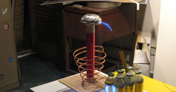
In the end, we must assemble our device as shown in the photo:
Step 1. Winding the high voltage coil
We wind the main high-voltage coil onto the tube with a 0.1-0.15 mm wire. I had 0.14 mm wire in stock. This is perhaps the most boring activity. Winding must be done as carefully as possible, turn to turn. You can use a rig, but I wound the spools by hand. By the way, I always do something in at least two copies. Why? First of all, skill. The second product turns out to be just candy, and there will always be a person who will start begging for the device (give it as a gift, sell it, let it be used, etc.). I give away the first, the second remains in the collection, the eye rejoices, friendship grows stronger, harmony in the world increases.

Step 2: Insulate the High Voltage Coil
The next important step is to insulate the high voltage coil. I won’t say that the reel needs to be impregnated with wax 20 times, wrapped in varnished cloth or boiled in oil. All these are Kolchak approaches. We are modern people, so we use high-voltage varnish (see the first photo. I don’t indicate the brand of varnish, you can Google it) and wide heat shrink. Apply varnish in two to three layers. Dry the layer for at least 20-30 minutes. The varnish applies perfectly. The result is great! The reel becomes simply eternal! The cost of varnish is not high. Three hundred rubles cylinder. I think there will be enough for a dozen similar devices. BUT!!!
The varnish turned out to be VERY TOXIC! Literally a minute later I had a headache and the cat started vomiting. The work had to be stopped. Urgently ventilate the room and stop applying varnish. I immediately had to run to the store. I should buy beer and milk for the cat to recover from poisoning:

According to good practice, applying varnish should be done under a hood, but (after saving myself and the cat) I did it outside. Fortunately, the weather was favorable, there was no wind or dust, and it didn’t rain. Then you need to put on a wide heat shrink and shrink the coil with a hot air gun. This must be done carefully, from the middle to the edges. It should be tight and even.
Step 3. Manufacturing the inductor and assembling the entire structure
Perhaps the most critical part of the generator. I have analyzed many designs of similar devices and many authors make the same mistake. Firstly, a fairly thin wire is used, and secondly, there is no uniform and significant (at least 1 cm) gap with the high-voltage coil and many turns are used. This is completely unnecessary. 2..4 turns in the first third of the high-voltage coil are enough. For the inductor we use a hollow annealed copper tube with a diameter of 8 mm, which ensures minimal inductance and simply excellent characteristics of the generator during operation. We wind three turns onto the rubber cuff into the grooves. To prevent the tube from breaking, fill it tightly with fine sand. Then carefully pour out the sand. After assembling the entire structure, everything should look like in the photo:

The copper tube is perhaps the most expensive item in this homemade product. As much as 150 rubles. Also purchased from a hardware store.
Some subtleties...
Subtleties are associated with the design of the inductor contacts. They are made of annealed copper strip and covered with heat shrink. This ensures minimal design inductance, which is very important. The contacts are hidden inside the coupling. All connections should be as short as possible and made with wide copper strips, which reduces various losses. We put an adapter-ring on the top of the device, which presses the copper round contact onto which the upper terminal of the high-voltage coil is soldered. The structure at the top is filled with liquid rubber. There is a mini-jack in the center.

Step 4. Connect and test the generator
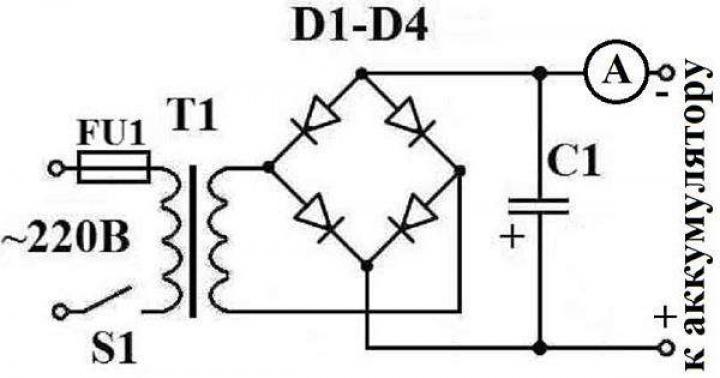
There are approximately 2 million ways to power such a device. Let's focus on the simplest - using the diagram shown in this figure:

You will need a couple of resistors, a capacitor, and don’t forget to place a transistor on the radiator. Denominations are indicated. I think the resource of the circuit is not large, but given the cheapness of transistors and the urgency of the desire to see the result, this no longer counts.

If everything is assembled correctly, the circuit will work immediately. If there is no generation, then switch the inductor contacts the other way around. It worked for me right away. Generation starts at 5-7 volts. Already at 6 volts the generation is stable, at 12 volts everything around is blazing. In the photo you can see that the entire structure is blown by a fan, since the transistor gets quite hot, even though it is placed on a radiator. Surprisingly, the circuit is very reliable. At 12 volts it works for hours and is very stable. When the lights are off and the light bulb is “dead,” it shines brightly. It is better to take a more powerful power source for the coil (with an output current of at least 2-3 amperes).

You can watch a video of the device in action.
It's not beer that kills people...
Let's not forget about safety. Such devices within a radius of up to 2-3 meters can easily damage thin electronics, such as a mobile phone, digital watch on a wrist, etc. A high-frequency high-voltage generator has little effect on humans due to the “skin effect,” but still be careful. Children, cats, birds and unbalanced citizens should be kept at some distance from such devices when they are turned on.
Remember this!
PS - At the request of some readers, I am adding a video with some details of the coil design. Video available at
The combination of several physical laws in one device is perceived by people far from physics as a miracle or a trick: discharges flying out, similar to lightning, fluorescent lamps glowing near the coil, not connected to a regular electrical network, etc. At the same time, you can assemble a Tesla coil with your own hands from standard parts sold in any electrical store. It is wiser to delegate setting up the device to those who are familiar with the principles of electricity, or to carefully study the relevant literature.
How Tesla invented his coil
Nikola Tesla - the greatest inventor of the 20th century
One of Nikola Tesla's areas of work at the end of the nineteenth century was the problem of transmitting electrical energy over long distances without wires. On May 20, 1891, at his lecture at the University of Columbia (USA), he demonstrated an amazing device to the staff of the American Institute of Electrical Engineering. The principle of its operation underlies modern energy-saving fluorescent lamps.
During experiments with the Ruhmkorff coil using the method of Heinrich Hertz, Tesla discovered overheating of the steel core and melting of the insulation between the windings when connecting a high-speed alternating current generator to the device. He then decided to modify the design by creating an air gap between the windings and moving the core to different positions. He added a capacitor to the circuit to prevent the coil from burning out.
Tesla coil operating principle and application
When the appropriate potential difference is reached, the excess energy comes out in the form of a streamer with a purple glow
This is a resonant transformer, the operation of which is based on the following algorithm:
- the capacitor is charged from a high-voltage transformer;
- when the required charge level is reached, a discharge occurs with a spark jumping;
- a short circuit occurs in the primary coil of the transformer, leading to oscillations;
- by selecting the connection point to the turns of the primary coil, they change the resistance and configure the entire circuit.
The resulting high voltage at the top of the secondary winding will produce impressive discharges in the air. For greater clarity, the operating principle of the device is compared to a swing that a person swings. A swing is an oscillatory circuit consisting of a transformer, a capacitor and a spark gap, a person is the primary winding, the swing stroke is the movement of electric current, and the lifting height is the potential difference. It is enough to push the swing several times with a certain effort, and it will rise to a considerable height.
In addition to educational and aesthetic use (demonstration of discharges and lamps glowing without connecting to a network), the device has found its use in the following industries:
- radio control;
- wireless transmission of data and energy;
- darsonvalization in medicine - treatment of the skin surface with weak high-frequency currents for toning and healing;
- ignition of gas discharge lamps;
- searching for leaks in vacuum systems, etc.
Making a Tesla coil with your own hands at home
Designing and creating a device is not difficult for people familiar with the principles of electrical engineering and electricity. However, even a beginner can cope with this task if he makes proper calculations and scrupulously follows the step-by-step instructions. In any case, before starting work, be sure to familiarize yourself with the safety regulations for working with high voltage.
Scheme
A Tesla coil consists of two coreless coils that send out a large pulse of current. The primary winding consists of 10 turns, the secondary - of 1000. Including a capacitor in the circuit allows you to minimize the loss of spark charge. The output potential difference exceeds millions of volts, which makes it possible to obtain spectacular and spectacular electrical discharges.
Before you start making a coil with your own hands, you need to study the diagram of its structure
Tools and materials
To assemble and subsequently operate the Tesla coil, you will need to prepare the following materials and equipment:
- transformer with output voltage from 4 kV 35 mA;
- bolts and metal ball for the arrester;
- capacitor with calculated capacity parameters of at least 0.33 µF 275 V;
- PVC pipe with a diameter of 75 mm;
- enameled copper wire with a cross-section of 0.3–0.6 mm - plastic insulation prevents breakdown;
- hollow metal ball;
- thick cable or copper tube with a cross section of 6 mm.
Step-by-step instructions for making a coil
Powerful batteries can also be used as a power source
The coil manufacturing algorithm consists of the following steps:
- Selection of power source. The best option for a beginner is transformers for neon signs. In any case, the output voltage on them should not be lower than 4 kV.
- Making a spark gap. The overall performance of the device depends on the quality of this element. In the simplest case, these can be ordinary bolts screwed in at a distance of a few millimeters from each other, between which a metal ball is installed. The distance is selected so that the spark flies when only the spark gap is connected to the transformer.
- Calculation of capacitor capacity. The resonant capacitance of the transformer is multiplied by 1.5 and the desired value is obtained. It is wiser to purchase a capacitor with the given parameters ready-made, since in the absence of sufficient experience it is difficult to assemble this element yourself so that it works. In this case, difficulties may arise in determining its nominal capacity. As a rule, in the absence of a large element, the coil capacitors are an assembly of three rows of 24 capacitors each. In this case, a 10 MΩ quenching resistor must be installed on each capacitor.
- Creating a secondary coil. The height of the coil is equal to five of its diameters. For this length, select a suitable available material, for example, a polyvinyl chloride pipe. It is wrapped with copper wire of 900–1000 turns, and then varnished to preserve its aesthetic appearance. A hollow metal ball is attached to the upper part, and the lower part is grounded. It is advisable to consider a separate grounding, since when using a common grounding, there is a high probability of failure of other electrical appliances. If a ready-made metal ball is not available, then it can be replaced with other similar options, made independently:
- wrap the plastic ball in foil, which should be carefully smoothed;
- wrap aluminum tape around a corrugated pipe rolled into a circle.
- Creation of the primary coil. The thickness of the tube prevents resistive losses; with increasing thickness, its ability to deform decreases. Therefore, a very thick cable or tube will bend poorly and crack at the bends. The pitch between the turns is maintained at 3–5 mm, the number of turns depends on the overall dimensions of the coil and is selected experimentally, as well as the location where the device is connected to the power source.
- Test run. After completing the initial settings, the coil is started.
Features of manufacturing other types of devices
It is mainly used for health purposes
To make a flat coil, a base is first prepared, on which two copper wires with a cross-section of 1.5 mm are laid in series parallel to the plane of the base. The top of the installation is varnished, prolonging its service life. Externally, this device is a container made of two spiral plates nested inside each other, connected to a power source.
The technology for manufacturing a mini-coil is identical to the algorithm discussed above for a standard transformer, but in this case fewer consumables will be needed, and it can be powered from a standard 9V Krona battery.
Video: how to create a mini Tesla coil
By connecting the coil to a transformer that outputs current through high-frequency musical waves, you can get a device whose discharges change depending on the rhythm of the music being played. Used in organizing shows and entertainment attractions.
Tesla coil is a high-frequency, high-voltage resonant transformer. Energy losses at high potential differences make it possible to obtain beautiful electrical phenomena in the form of lightning, self-igniting lamps that respond to the musical rhythm of discharges, etc. This device can be assembled from standard electrical parts. However, one should not forget about precautions both during creation and during use of the device.
Nikola Tesla is a legendary figure, and the meaning of some of his inventions is still debated to this day. We won’t go into mysticism, but rather talk about how to make something spectacular according to Tesla’s “recipes”. This is a Tesla coil. Having seen it once, you will never forget this incredible and amazing sight!
General information
If we talk about the simplest such transformer (coil), then it consists of two coils that do not have a common core. The primary winding must have at least a dozen turns of thick wire. At least 1000 turns are already wound on the secondary one. Please note that the Tesla coil has one that is 10-50 times greater than the ratio of the number of turns on the second winding to the first.
The output voltage of such a transformer can exceed several million volts. It is this circumstance that ensures the occurrence of spectacular discharges, the length of which can reach several meters at once.
When were the transformer's capabilities first demonstrated to the public?
In the town of Colorado Springs, a generator at a local power plant once completely burned out. The reason was that the current from it went to power the primary winding. During this ingenious experiment, the scientist first proved to the community that the existence of a standing electromagnetic wave is a reality. If your dream is a Tesla coil, the most difficult thing to do with your own hands is the primary winding.
In general, making it yourself is not so difficult, but it is much more difficult to give the finished product a visually attractive appearance.
The simplest transformer

First, you will have to find a high voltage source somewhere, at least 1.5 kV. However, it is best to immediately count on 5 kV. Then we attach it all to a suitable capacitor. If its capacity is too large, you can experiment a little with diode bridges. After this, you make the so-called spark gap, for the sake of which the entire Tesla coil is created.
It’s easy to do: take a couple of wires, and then twist them with electrical tape so that the bare ends point in one direction. We very carefully adjust the gap between them so that the breakdown occurs at a voltage slightly higher than that for the power source. Don't worry: since the current is alternating, the peak voltage will always be slightly higher than stated. After this, the entire structure can be connected to the primary winding.
In this case, to make a secondary one, you can wind only 150-200 turns on any cardboard sleeve. If you do everything correctly, you will get a good discharge, as well as noticeable branching. It is very important to ground the output from the second coil well.
This is how the simplest Tesla coil turned out. Anyone who has at least minimal knowledge of electrical engineering can do it with their own hands.
We design a more “serious” device

All this is good, but how does a transformer work, which is not a shame to show even at some exhibition? Making a more powerful device is quite possible, but it will require a lot more work. First, we warn you that to conduct such experiments you must have very reliable wiring, otherwise disaster will not be avoided! So, what should you take into account? Tesla coils, as we already said, need really high voltage.
It must be at least 6 kV, otherwise you won’t see beautiful discharges, and the settings will constantly get lost. In addition, the spark plug should be made only from solid pieces of copper, and for the sake of your own safety, they should be fixed as firmly as possible in one position. The power of the entire “economy” should be at least 60 W, but it is better to take 100 or more. If this value is lower, then you will definitely not get a truly spectacular Tesla coil.
Very important! Both the capacitor and the primary winding must ultimately form a specific oscillatory circuit that enters into a state of resonance with the secondary winding.
Keep in mind that the winding can resonate in several different ranges at once. Experiments have shown that the frequency is 200, 400, 800 or 1200 kHz. As a rule, all this depends on the condition and location of the primary winding. If you don’t have one, you will have to experiment with the capacitance of the capacitor, and also change the number of turns on the winding.
We remind you once again that we are discussing a bifilar Tesla coil (with two coils). So the issue of winding should be approached seriously, because otherwise nothing meaningful will come of the idea.
Some information about capacitors

It is better to take the capacitor itself with a not too outstanding capacity (so that it has time to accumulate charge in time) or use a diode bridge designed for rectifying alternating current. Let us immediately note that the use of a bridge is more justified, since capacitors of almost any capacity can be used, but in this case you will have to take a special resistor to discharge the structure. It gives off a very (!) electric shock.
Note that we are not considering a Tesla coil on a transistor. After all, you simply won’t find transistors with the required characteristics.
Important!
In general, we remind you once again: before assembling the Tesla coil, check the condition of all wiring in the house or apartment, make sure there is a high-quality grounding! This may seem like a boring exhortation, but such tension is not to be trifled with!
It is imperative to very reliably isolate the windings from each other, since otherwise you will be guaranteed to break through. On the secondary winding, it is advisable to make insulation between the layers of turns, since any more or less deep scratch on the wire will be decorated with a small but extremely dangerous discharge corona. And now - let's get to work!
Let's get started
As you can see, you will not need so many elements for assembly. You just need to remember that for proper operation of the device you need not only to assemble it correctly, but also to configure it correctly! However, first things first.
Transformers (MOTs) can be removed from any old microwave oven. This is almost standard, but it has one important difference: its core almost always operates in saturation mode. Thus, a very compact and simple device can easily output up to 1.5 kV. Unfortunately, they also have specific disadvantages.
So, the value of the no-load current is approximately three to four amperes, and the heating even during idle time is very high. For an average microwave oven, the MOT produces about 2-2.3 kV, and is equal to approximately 500-850 mA.
Characteristics of ILOs

Attention! In these transformers, the primary winding starts at the bottom, while the secondary winding is located at the top. This design provides better insulation of all windings. As a rule, on the “secondary” there is a filament winding from the magnetron (approximately 3.6 Volts). Between the two layers of metal, an attentive craftsman may notice a couple of metal bridges. These are magnetic shunts. What are they needed for?
The fact is that they close on themselves some part of the magnetic field that the primary winding creates. This is done to stabilize the field and the current itself on the second winding. If they are not there, then at the slightest short circuit the entire load goes to the “primary”, and its resistance is very small. Thus, these small parts protect the transformer and you, as they prevent many unpleasant consequences. Oddly enough, is it still better to remove them? Why?
Remember that in a microwave oven the problem of overheating of this important device is solved by installing powerful fans. If you have a transformer that does not have shunts, then its power and heat dissipation are much higher. For all imported microwave ovens, they are most often thoroughly filled with epoxy resin. So why should they be removed? The fact is that in this case the current “drawdown” under load is significantly reduced, which is very important for our purposes. What to do with overheating? We recommend placing the ILO in
By the way, a flat Tesla coil generally does without a ferromagnetic core and a transformer, but requires an even higher voltage supply of current. Because of this, trying something similar at home is strongly discouraged.
Once again about safety precautions
A small addition: the voltage on the secondary winding is such that an electric shock if it breaks down will lead to guaranteed death. Remember that the Tesla coil circuit assumes a current strength of 500-850 A. The maximum value of this value, which still leaves a chance of survival, is... 10 A. So when working, do not forget for a second about the simplest precautions!
Where and for how much can I buy components?

Alas, there is some bad news: firstly, a decent ILO costs at least two thousand rubles. Secondly, finding it on the shelves of even specialized stores is almost impossible. There is only hope for the collapses and “flea markets”, through which you will have to run a lot in search of what you are looking for.
If possible, be sure to use the MOT from the old Soviet Electronika microwave oven. It is not as compact as imported analogues, but it operates in the mode of a regular transformer. Its industrial designation is TV-11-3-220-50. It has a power of approximately 1.5 kW, an output of about 2200 Volts, and a current strength of 800 mA. In short, the parameters are quite decent even for our time. In addition, it has an additional 12V winding, ideal as a power source for the fan that will cool the Tesla spark plug.
What else should I use?
High-quality high-voltage ceramic capacitors of the K15U1, K15U2, TGK, KTK, K15-11, K15-14 series. It is difficult to find them, so it is better to have professional electricians as good friends. What about the high pass filter? You will need two coils that can reliably filter out high frequencies. Each of them must contain at least 140 turns of high-quality copper wire (varnished).
Some information about the spark generator
The spark generator is designed to excite oscillations in the circuit. If it is not in the circuit, then the power will flow, but the resonance will not. In addition, the power supply begins to “punch” through the primary winding, which is almost guaranteed to lead to a short circuit! If the spark switch is not closed, the high voltage capacitors cannot charge. As soon as it closes, oscillations begin in the circuit. It is to prevent certain problems that throttles are used. When the spark plug closes, the inductor prevents current leakage from the power supply, and only then, when the circuit is open, accelerated charging of the capacitors begins.

Device characteristics
Finally, we will say a few more words about the Tesla transformer itself: for the primary winding, you are unlikely to be able to find a copper wire of the required diameter, so it is easier to use copper tubes from refrigeration equipment. The number of turns is from seven to nine. At least 400 (up to 800) turns must be wound on the secondary. It is impossible to determine the exact amount, so experiments will have to be carried out. One output is connected to the TOP (lightning emitter), and the second is very (!) reliably grounded.
What is the emitter made of? Use an ordinary ventilation corrugation for this. Before you make a Tesla coil, a photo of which is here, be sure to think about how to design it more original. Below are some tips.
In conclusion…
Alas, this spectacular device has no practical application to this day. Some demonstrate experiments in institutes, others make money from this by arranging “miracles of electricity” parks. In America, a very wonderful friend a couple of years ago actually made a Christmas tree out of a Tesla coil...
To make it more beautiful, he applied various substances to the lightning emitter. Keep in mind: boric acid makes the tree green, manganese makes the tree blue, and lithium makes it crimson. There are still debates about the true purpose of the invention of the brilliant scientist, but today it is a common attraction.
Here's how to make a Tesla coil.