Sooner or later, the car may stop starting due to low battery charge. Long-term operation leads to the fact that the generator is no longer able to charge the battery. In this case, it is necessary keep at least a simple charger on hand for a car battery.
Nowadays, conventional transformer charging is being replaced by a new generation of improved models. Pulse and automatic chargers are very popular among them. Let's get acquainted with the principle of their work, and for those who already want to tinker, go
Pulse chargers for batteries
 Unlike a transformer, a pulse charger for a car battery provides a full charge. However, its main advantages are ease of use, significantly lower price and compact size.
Charging the battery with pulsed devices is carried out in two stages: first at constant voltage, and then at constant current(often the charging process is automated). Basically, modern chargers consist of the same type, but very complex circuits, so if they break down, it is better for an inexperienced owner to purchase a new one.
Lead acid batteries are very sensitive to temperature. In hot weather, the battery charge level should not be lower than 50%, and in severe frost conditions, not lower than 75%. Otherwise, the battery may stop working and will need to be recharged. Pulse devices are very suitable for this and do not damage the battery.
Automatic chargers for car batteries
 For inexperienced drivers, an automatic charger is best for a car battery. It has a number of functions and protections that will notify you of incorrect pole connection and prohibit the flow of electric current.
Some devices are designed to measure the capacity and charge level of a battery, so they are used to charge any type of battery.
The electrical circuits of automatic devices contain a special timer, thanks to which several different cycles can be carried out: full charging, fast charging and battery recovery. After the process is completed the device will inform you about this and turn off the load.
Very often, due to improper use of the battery, sulfitation forms on its plates. The charge-discharge cycle not only rids the battery of salts that have appeared, but also extends its service life.
Despite the low price of modern chargers, there are times when proper charging is not at hand. That's why It’s quite possible to make a charger for a car battery with your own hands. Let's look at a few examples of homemade devices.
Charging the battery from the computer power supply
Some people may still have old computers with a working power supply that could make an excellent charger. It is suitable for almost any battery. Circuit diagram of a simple charger from a computer power supply
Almost every power supply has a PWM controller in place of DA1 - a controller based on a TL494 chip or a similar KA7500. To charge the battery, a current of 10% of the full battery capacity is required(usually from 55 to 65Ah), so any power supply with a power of over 150 W is capable of producing it. Initially, you need to unsolder unnecessary wires from sources -5 V, -12 V, +5 V, +12 V.
Next, you need to unsolder resistor R1, which is replaced with a trimming resistor with the highest value of 27 kOhm. The voltage from the +12 V bus will be transmitted to the upper pin. Then pin 16 is disconnected from the main wire, and pins 14 and 15 are simply cut at the connection point.
This is approximately what a power supply unit should look like at the initial stage of rework. 
Now a potentiometer-current regulator R10 is installed on the back wall of the power supply, and 2 cords are passed through: one for network, the other for connecting to the battery terminals. It is recommended to prepare a block of resistors in advance, with the help of which connection and adjustment are much more convenient.

To manufacture it, two current measuring resistors 5W8R2J with a power of 5 W are connected in parallel. Eventually the total power reaches 10 W, and the required resistance is 0.1 Ohm. To set up the charger, a trimming resistor is attached to the same board. Some part of the print track needs to be removed. This will help eliminate the possibility of unwanted connections between the device body and the main circuit. You should pay attention to this for 2 reasons:
Electrical connections and a board with a resistor block are installed according to the above diagram. 
Pins 1, 14, 15, 16 on the chip first you should tin and then solder the stranded thin wires.
Full charge will be determined by open circuit voltage ranging from 13.8 to 14.2 V. It must be set with a variable resistor with the potentiometer R10 in the middle position. To connect the leads to the battery terminals, alligator clips are installed at their ends. The insulating tubes on the clamps must be of different colors. Typically, red corresponds to “plus” and black to “minus”. Do not get confused with connecting wires, otherwise this will lead to damage to the device..
Ultimately, a charger for a car battery from a computer power supply should look something like this. 
If the charger will be used exclusively for charging the battery, then you can dispense with the volt and ammeter. To set the initial current, it is enough to use the graduated scale of potentiometer R10 with a value of 5.5-6.5 A. Almost the entire charging process does not require human intervention.
This type of charger eliminates the possibility of overheating or overcharging the battery.
The simplest memory using an adapter
 An adapted 12-volt adapter acts as a DC source here.. In this case, a charger circuit for a car battery is not required.
The main thing to take into account is an important feature - The voltage of the power source must be equal to the voltage of the battery itself, otherwise the battery will not charge.
The end of the adapter wire is cut off and exposed to 5 cm. Next, the wires with opposite charges are separated from each other by 40 cm. Then a crocodile is placed on the end of each wire(type of terminals), each of which should be a different color to avoid confusion with polarity. The clamps are connected in series to the battery (“from plus to plus”, “from minus to minus”) and then the adapter is turned on.
The only difficulty is choosing the right power source. It is also worth paying attention to the fact that the battery may overheat during the process. In this case, you need to interrupt charging for a while.
A xenon lamp is one of the best light sources for cars. Find out what the penalty is for xenon before installing it.
Anyone can install parking sensors. You can verify this on this page. Go ahead and find out how to install parking sensors yourself.
Many drivers have proven that the Strelka police radar does not forgive mistakes. By following this link /tuning/elektronika/radar-detektor-protiv-strelki.html you can find out which radar detectors can protect the driver from a fine.
Charger made from a household light bulb and diode
To create a simple memory you will need a few simple elements:
- household light bulb with a power of up to 200 W. The speed of battery charging depends on its power - the higher the faster;
- A semiconductor diode that conducts electricity in only one direction. As such a diode You can use a laptop charger;
- wires with terminals and plug.
The connection diagram of the elements and the battery charging process are clearly demonstrated in this video.
If the circuit is configured correctly, the light bulb will burn at full intensity, and if it does not light up at all, then the circuit needs to be modified. It is possible that the light will not light up if the battery is fully charged, which is unlikely (the voltage at the terminals is high and the current value is low).
Charging takes approximately 10 hours, after which be sure to unplug the charger, otherwise overheating of the battery will lead to its failure.
In emergency cases, you can recharge the battery using a sufficiently powerful diode and a heater using current from the mains. The sequence of connecting to the network should be as follows: diode, heater, battery. This method consumes a large amount of electricity, and the efficiency is significantly low - 1%. This homemade charger for a car battery can be considered the simplest, but extremely unreliable.
Conclusion
 Creating the simplest charger that will not damage your battery will require a lot of technical knowledge. WITH There is now a wide selection of chargers on the market with great functionality and a simple interface to work with.
Therefore, if possible, it is better to have a reliable device with you with a guarantee that the battery will not be compromised and will continue to operate reliably.
Take a look at this video. It shows another way to quickly charge the battery with your own hands.
Many car enthusiasts have a need to charge the battery. Some use branded chargers for these purposes, others use homemade chargers made at home. How to make and how to properly charge the battery with such a device? We will talk about this below.
[Hide]
Design and principle of operation of the charger
A simple battery charger is a device used to restore battery charge. The essence of the functioning of any charger is that this device allows you to convert voltage from a 220-volt household network into the voltage required for. Today there are many types of chargers, but any device is based on two main components - a transformer device and a rectifier (the author of the video on how to choose a charging device is the Battery Manager channel).
The process itself consists of several stages:
- when recharging the battery, the charging current parameter decreases and the resistance level increases;
- at the moment when the voltage parameter approaches 12 volts, the charging current level reaches zero - at this moment the battery will be fully charged, and the charger can be turned off.
Instructions for making a simple charger with your own hands
If you want to make a charger for a 12 or 6 volt car battery, then we can help you with this. Of course, if you have never encountered such a need before, but want to get a functional device, then it is better to purchase an automatic one. After all, a homemade charger for a car battery will not have the same functions as a branded device.
Tools and materials
So, to make a battery charger with your own hands, you will need the following items:
- soldering iron with consumables;
- textolite plate;
- wire with plug for connecting to a household network;
- radiator from a computer.
Depending on, an ammeter and other components can be additionally used to allow proper charging and charge control. Of course, to make a car charger, you also need to prepare a transformer assembly and a rectifier for charging the battery. By the way, the housing itself can be taken from an old ammeter. The ammeter body has several holes to which you can connect the necessary elements. If you don't have an ammeter, you can find something similar.
Photo gallery “Getting ready for assembly”


Stages
To build a charger for a car battery with your own hands, do the following:
- So, first you need to work with the transformer. We will show an example of making a homemade charger with a TS-180-2 transformer device - such a device can be removed from an old tube TV. Such devices are equipped with two windings - primary and secondary, and at the output of each secondary component the current is 4.7 amperes and the voltage is 6.4 volts. Accordingly, a homemade charger will produce 12.8 volts, but for this the windings must be connected in series.
- To connect the windings, you will need a cable whose cross-section will be less than 2.5 mm2.
- Using a jumper, you need to connect both the secondary and primary components.
- Then you will need a diode bridge; to equip it, take four diode elements, each of which must be designed to operate under current conditions of at least 10 amperes.
- The diodes are fixed on the textolite plate, after which they will need to be connected correctly.
- Cables are connected to the output diode components, with the help of which the homemade charger will be connected to the battery. To measure the voltage level, you can additionally use an electromagnetic head, but if this parameter does not interest you, you can install an ammeter designed for direct current. After completing these steps, the charger will be ready with your own hands (the author of the video about making the simplest device in its design is the Soldering Iron TV channel).
How to charge a battery with a homemade charger?
Now you know how to make a charger for your car at home. But how to use it correctly so that it does not affect the service life of a charged battery?
- When connecting, you must always observe polarity so as not to mix up the terminals. If you make a mistake and mix up the terminals, you will simply “kill” the battery. So the positive wire from the charger is always connected to the battery positive, and the negative wire to the negative.
- Never try to test the battery for a spark - despite the fact that there are many recommendations on the Internet regarding this, under no circumstances should you short-circuit the wires. This will negatively affect the operation of the charger and the battery itself in the future.
- When the device is connected to the battery, it must be disconnected from the network. The same goes for turning it off.
- When manufacturing and assembling the charger, and during its use, always be careful. To avoid injury, always follow safety precautions, particularly when working with electrical components. If errors are made during manufacturing, this can cause not only personal injury, but also failure of the battery as a whole.
- Never leave a working charger unattended - you need to understand that this is a homemade device and anything can happen during its operation. When recharging, the device and battery should be kept in a ventilated area, as far as possible from explosive materials.
Video “An example of assembling a homemade charger with your own hands”
The video below shows an example of assembling a homemade charger for a car battery using a more complex scheme with basic recommendations and tips (the author of the video is the AKA KASYAN channel).
The photo shows a homemade automatic charger for charging 12 V car batteries with a current of up to 8 A, assembled in a housing from a B3-38 millivoltmeter.
Why do you need to charge your car battery?
charger
The battery in the car is charged using an electric generator. To protect electrical equipment and devices from the increased voltage generated by a car generator, a relay-regulator is installed after it, which limits the voltage in the car’s on-board network to 14.1 ± 0.2 V. To fully charge the battery, a voltage of at least 14.5 is required IN.
Thus, it is impossible to fully charge the battery from a generator and before the onset of cold weather it is necessary to recharge the battery from a charger.
Analysis of charger circuits
The scheme for making a charger from a computer power supply looks attractive. The structural diagrams of computer power supplies are the same, but the electrical ones are different, and modification requires high radio engineering qualifications.
I was interested in the capacitor circuit of the charger, the efficiency is high, it does not generate heat, it provides a stable charging current regardless of the state of charge of the battery and fluctuations in the supply network, and is not afraid of output short circuits. But it also has a drawback. If during charging the contact with the battery is lost, the voltage on the capacitors increases several times (the capacitors and transformer form a resonant oscillatory circuit with the frequency of the mains), and they break through. It was necessary to eliminate only this one drawback, which I managed to do.
The result was a charger circuit without the above-mentioned disadvantages. For more than 16 years I have been charging any 12 V acid batteries with it. The device works flawlessly.
Schematic diagram of a car charger
Despite its apparent complexity, the circuit of a homemade charger is simple and consists of only a few complete functional units.

If the circuit to repeat seems complicated to you, then you can assemble a more one that works on the same principle, but without the automatic shutdown function when the battery is fully charged.
Current limiter circuit on ballast capacitors
In a capacitor car charger, regulation of the magnitude and stabilization of the battery charge current is ensured by connecting ballast capacitors C4-C9 in series with the primary winding of the power transformer T1. The larger the capacitor capacity, the greater the battery charging current.

In practice, this is a complete version of the charger; you can connect a battery after the diode bridge and charge it, but the reliability of such a circuit is low. If contact with the battery terminals is broken, the capacitors may fail.
The capacitance of the capacitors, which depends on the magnitude of the current and voltage on the secondary winding of the transformer, can be approximately determined by the formula, but it is easier to navigate using the data in the table.
To regulate the current in order to reduce the number of capacitors, they can be connected in parallel in groups. My switching is carried out using a two-bar switch, but you can install several toggle switches.
Protection circuit
from incorrect connection of battery poles
The protection circuit against polarity reversal of the charger in case of incorrect connection of the battery to the terminals is made using relay P3. If the battery is connected incorrectly, the VD13 diode does not pass current, the relay is de-energized, the K3.1 relay contacts are open and no current flows to the battery terminals. When connected correctly, the relay is activated, contacts K3.1 are closed, and the battery is connected to the charging circuit. This reverse polarity protection circuit can be used with any charger, both transistor and thyristor. It is enough to connect it to the break in the wires with which the battery is connected to the charger.

Circuit for measuring current and voltage of battery charging
Thanks to the presence of switch S3 in the diagram above, when charging the battery, it is possible to control not only the amount of charging current, but also the voltage. In the upper position of S3, the current is measured, in the lower position the voltage is measured. If the charger is not connected to the mains, the voltmeter will show the battery voltage, and when the battery is charging, the charging voltage. An M24 microammeter with an electromagnetic system is used as a head. R17 bypasses the head in current measurement mode, and R18 serves as a divider when measuring voltage.
Automatic charger shutdown circuit
when the battery is fully charged
To power the operational amplifier and create a reference voltage, a DA1 type 142EN8G 9V stabilizer chip is used. This microcircuit was not chosen by chance. When the temperature of the microcircuit body changes by 10º, the output voltage changes by no more than hundredths of a volt.
The system for automatically turning off charging when the voltage reaches 15.6 V is made on half of the A1.1 chip. Pin 4 of the microcircuit is connected to a voltage divider R7, R8 from which a reference voltage of 4.5 V is supplied to it. Pin 4 of the microcircuit is connected to another divider using resistors R4-R6, resistor R5 is a tuning resistor to set the operating threshold of the machine. The value of resistor R9 sets the threshold for switching on the charger to 12.54 V. Thanks to the use of diode VD7 and resistor R9, the necessary hysteresis is provided between the switch-on and switch-off voltages of the battery charge.

The scheme works as follows. When connecting a car battery to a charger, the voltage at the terminals of which is less than 16.5 V, a voltage sufficient to open transistor VT1 is established at pin 2 of microcircuit A1.1, the transistor opens and relay P1 is activated, connecting contacts K1.1 to the mains through a block of capacitors the primary winding of the transformer and battery charging begins.
As soon as the charge voltage reaches 16.5 V, the voltage at output A1.1 will decrease to a value insufficient to maintain transistor VT1 in the open state. The relay will turn off and contacts K1.1 will connect the transformer through the standby capacitor C4, at which the charge current will be equal to 0.5 A. The charger circuit will be in this state until the voltage on the battery decreases to 12.54 V. As soon as the voltage will be set equal to 12.54 V, the relay will turn on again and charging will proceed at the specified current. It is possible, if necessary, to disable the automatic control system using switch S2.
Thus, the system of automatic monitoring of battery charging will eliminate the possibility of overcharging the battery. The battery can be left connected to the included charger for at least a whole year. This mode is relevant for motorists who drive only in the summer. After the end of the racing season, you can connect the battery to the charger and turn it off only in the spring. Even if there is a power outage, when it returns, the charger will continue to charge the battery as normal.
The principle of operation of the circuit for automatically turning off the charger in case of excess voltage due to the lack of load collected on the second half of the operational amplifier A1.2 is the same. Only the threshold for completely disconnecting the charger from the supply network is set to 19 V. If the charging voltage is less than 19 V, the voltage at output 8 of the A1.2 chip is sufficient to hold the transistor VT2 in the open state, in which voltage is applied to the relay P2. As soon as the charging voltage exceeds 19 V, the transistor will close, the relay will release contacts K2.1 and the voltage supply to the charger will completely stop. As soon as the battery is connected, it will power the automation circuit, and the charger will immediately return to working condition.
Automatic charger design
All parts of the charger are placed in the housing of the V3-38 milliammeter, from which all its contents have been removed, except for the pointer device. The installation of elements, except for the automation circuit, is carried out using a hinged method.

The housing design of the milliammeter consists of two rectangular frames connected by four corners. There are holes made in the corners with equal spacing, to which it is convenient to attach parts.

The TN61-220 power transformer is secured with four M4 screws on an aluminum plate 2 mm thick, the plate, in turn, is attached with M3 screws to the lower corners of the case. The TN61-220 power transformer is secured with four M4 screws on an aluminum plate 2 mm thick, the plate, in turn, is attached with M3 screws to the lower corners of the case. C1 is also installed on this plate. The photo shows a view of the charger from below.

A 2 mm thick fiberglass plate is also attached to the upper corners of the case, and capacitors C4-C9 and relays P1 and P2 are screwed to it. A printed circuit board is also screwed to these corners, on which an automatic battery charging control circuit is soldered. In reality, the number of capacitors is not six, as in the diagram, but 14, since in order to obtain a capacitor of the required value it was necessary to connect them in parallel. The capacitors and relays are connected to the rest of the charger circuit via a connector (blue in the photo above), which made it easier to access other elements during installation.

A finned aluminum radiator is installed on the outer side of the rear wall to cool the power diodes VD2-VD5. There is also a 1 A Pr1 fuse and a plug (taken from the computer power supply) for supplying power.

The charger's power diodes are secured using two clamping bars to the radiator inside the case. For this purpose, a rectangular hole is made in the rear wall of the case. This technical solution allowed us to minimize the amount of heat generated inside the case and save space. The diode leads and supply wires are soldered onto a loose strip made of foil fiberglass.

The photo shows a view of a homemade charger on the right side. The installation of the electrical circuit is made with colored wires, alternating voltage - brown, positive - red, negative - blue wires. The cross-section of the wires coming from the secondary winding of the transformer to the terminals for connecting the battery must be at least 1 mm 2.

The ammeter shunt is a piece of high-resistance constantan wire about a centimeter long, the ends of which are sealed in copper strips. The length of the shunt wire is selected when calibrating the ammeter. I took the wire from the shunt of a burnt pointer tester. One end of the copper strips is soldered directly to the positive output terminal; a thick conductor coming from the contacts of relay P3 is soldered to the second strip. The yellow and red wires go to the pointer device from the shunt.
Printed circuit board of the charger automation unit
The circuit for automatic regulation and protection against incorrect connection of the battery to the charger is soldered on a printed circuit board made of foil fiberglass.

The photo shows the appearance of the assembled circuit. The printed circuit board design for the automatic control and protection circuit is simple, the holes are made with a pitch of 2.5 mm.

The photo above shows a view of the printed circuit board from the installation side with parts marked in red. This drawing is convenient when assembling a printed circuit board.

The printed circuit board drawing above will be useful when manufacturing it using laser printer technology.

And this drawing of a printed circuit board will be useful when applying current-carrying tracks of a printed circuit board manually.
The scale of the pointer instrument of the V3-38 millivoltmeter did not fit the required measurements, so I had to draw my own version on the computer, print it on thick white paper and glue the moment on top of the standard scale with glue.

Thanks to the larger scale size and calibration of the device in the measurement area, the voltage reading accuracy was 0.2 V.
Wires for connecting the charger to the battery and network terminals
The wires for connecting the car battery to the charger are equipped with alligator clips on one side and split ends on the other side. The red wire is selected to connect the positive terminal of the battery, and the blue wire is selected to connect the negative terminal. The cross-section of the wires for connecting to the battery device must be at least 1 mm 2.

The charger is connected to the electrical network using a universal cord with a plug and socket, as is used to connect computers, office equipment and other electrical appliances.
About Charger Parts
Power transformer T1 is used type TN61-220, the secondary windings of which are connected in series, as shown in the diagram. Since the efficiency of the charger is at least 0.8 and the charging current usually does not exceed 6 A, any transformer with a power of 150 watts will do. The secondary winding of the transformer should provide a voltage of 18-20 V at a load current of up to 8 A. If there is no ready-made transformer, then you can take any suitable power and rewind the secondary winding. You can calculate the number of turns of the secondary winding of a transformer using a special calculator.
Capacitors C4-C9 type MBGCh for a voltage of at least 350 V. You can use capacitors of any type designed to operate in alternating current circuits.
Diodes VD2-VD5 are suitable for any type, rated for a current of 10 A. VD7, VD11 - any pulsed silicon ones. VD6, VD8, VD10, VD5, VD12 and VD13 are any that can withstand a current of 1 A. LED VD1 is any, VD9 I used type KIPD29. A distinctive feature of this LED is that it changes color when the connection polarity is changed. To switch it, contacts K1.2 of relay P1 are used. When charging with the main current, the LED lights up yellow, and when switching to the battery charging mode, it lights up green. Instead of a binary LED, you can install any two single-color LEDs by connecting them according to the diagram below.

The operational amplifier chosen is KR1005UD1, an analogue of the foreign AN6551. Such amplifiers were used in the sound and video unit of the VM-12 video recorder. The good thing about the amplifier is that it does not require bipolar power supply or correction circuits and remains operational at a supply voltage of 5 to 12 V. It can be replaced with almost any similar one. For example, LM358, LM258, LM158 are good for replacing microcircuits, but their pin numbering is different, and you will need to make changes to the printed circuit board design.
Relays P1 and P2 are any for a voltage of 9-12 V and contacts designed for a switching current of 1 A. P3 for a voltage of 9-12 V and a switching current of 10 A, for example RP-21-003. If there are several contact groups in the relay, then it is advisable to solder them in parallel.
Switch S1 of any type, designed to operate at a voltage of 250 V and having a sufficient number of switching contacts. If you don’t need a current regulation step of 1 A, then you can install several toggle switches and set the charging current, say, 5 A and 8 A. If you charge only car batteries, then this solution is completely justified. Switch S2 is used to disable the charge level control system. If the battery is charged with a high current, the system may operate before the battery is fully charged. In this case, you can turn off the system and continue charging manually.
Any electromagnetic head for a current and voltage meter is suitable, with a total deviation current of 100 μA, for example type M24. If there is no need to measure voltage, but only current, then you can install a ready-made ammeter designed for a maximum constant measuring current of 10 A, and monitor the voltage with an external dial tester or multimeter by connecting them to the battery contacts.
Setting up the automatic adjustment and protection unit of the automatic control unit
If the board is assembled correctly and all radio elements are in good working order, the circuit will work immediately. All that remains is to set the voltage threshold with resistor R5, upon reaching which the battery charging will be switched to low current charging mode.
The adjustment can be made directly while charging the battery. But still, it’s better to play it safe and check and configure the automatic control and protection circuit of the automatic control unit before installing it in the housing. To do this, you will need a DC power supply, which has the ability to regulate the output voltage in the range from 10 to 20 V, designed for an output current of 0.5-1 A. As for measuring instruments, you will need any voltmeter, pointer tester or multimeter designed to measure DC voltage, with a measurement limit from 0 to 20 V.
Checking the voltage stabilizer
After installing all the parts on the printed circuit board, you need to apply a supply voltage of 12-15 V from the power supply to the common wire (minus) and pin 17 of the DA1 chip (plus). By changing the voltage at the output of the power supply from 12 to 20 V, you need to use a voltmeter to make sure that the voltage at output 2 of the DA1 voltage stabilizer chip is 9 V. If the voltage is different or changes, then DA1 is faulty.
Microcircuits of the K142EN series and analogues have protection against short circuits at the output, and if you short-circuit its output to the common wire, the microcircuit will enter protection mode and will not fail. If the test shows that the voltage at the output of the microcircuit is 0, this does not always mean that it is faulty. It is quite possible that there is a short circuit between the tracks of the printed circuit board or one of the radio elements in the rest of the circuit is faulty. To check the microcircuit, it is enough to disconnect its pin 2 from the board and if 9 V appears on it, it means that the microcircuit is working, and it is necessary to find and eliminate the short circuit.
Checking the surge protection system
I decided to start describing the operating principle of the circuit with a simpler part of the circuit, which is not subject to strict operating voltage standards.
The function of disconnecting the charger from the mains in the event of a battery disconnection is performed by a part of the circuit assembled on an operational differential amplifier A1.2 (hereinafter referred to as the op-amp).
Operating principle of an operational differential amplifier
Without knowing the operating principle of the op-amp, it is difficult to understand the operation of the circuit, so I will give a brief description. The op-amp has two inputs and one output. One of the inputs, which is designated in the diagram by a “+” sign, is called non-inverting, and the second input, which is designated by a “–” sign or a circle, is called inverting. The word differential op-amp means that the voltage at the output of the amplifier depends on the difference in voltage at its inputs. In this circuit, the operational amplifier is switched on without feedback, in comparator mode – comparing input voltages.
Thus, if the voltage at one of the inputs remains unchanged, and at the second it changes, then at the moment of passing through the point of equality of voltages at the inputs, the voltage at the output of the amplifier will change abruptly.
Testing the Surge Protection Circuit
Let's return to the diagram. The non-inverting input of amplifier A1.2 (pin 6) is connected to a voltage divider assembled across resistors R13 and R14. This divider is connected to a stabilized voltage of 9 V and therefore the voltage at the point of connection of the resistors never changes and is 6.75 V. The second input of the op-amp (pin 7) is connected to the second voltage divider, assembled on resistors R11 and R12. This voltage divider is connected to the bus through which the charging current flows, and the voltage on it changes depending on the amount of current and the state of charge of the battery. Therefore, the voltage value at pin 7 will also change accordingly. The divider resistances are selected in such a way that when the battery charging voltage changes from 9 to 19 V, the voltage at pin 7 will be less than at pin 6 and the voltage at the op-amp output (pin 8) will be more than 0.8 V and close to the op-amp supply voltage. The transistor will be open, voltage will be supplied to the winding of relay P2 and it will close contacts K2.1. The output voltage will also close diode VD11 and resistor R15 will not participate in the operation of the circuit.
As soon as the charging voltage exceeds 19 V (this can only happen if the battery is disconnected from the output of the charger), the voltage at pin 7 will become greater than at pin 6. In this case, the voltage at the op-amp output will abruptly decrease to zero. The transistor will close, the relay will de-energize and contacts K2.1 will open. The supply voltage to the RAM will be interrupted. At the moment when the voltage at the output of the op-amp becomes zero, diode VD11 opens and, thus, R15 is connected in parallel to R14 of the divider. The voltage at pin 6 will instantly decrease, which will eliminate false positives when the voltages at the op-amp inputs are equal due to ripple and interference. By changing the value of R15, you can change the hysteresis of the comparator, that is, the voltage at which the circuit will return to its original state.
When the battery is connected to the RAM, the voltage at pin 6 will again be set to 6.75 V, and at pin 7 it will be less and the circuit will begin to operate normally.
To check the operation of the circuit, it is enough to change the voltage on the power supply from 12 to 20 V and connect a voltmeter instead of relay P2 to observe its readings. When the voltage is less than 19 V, the voltmeter should show a voltage of 17-18 V (part of the voltage will drop across the transistor), and if it is higher, zero. It is still advisable to connect the relay winding to the circuit, then not only the operation of the circuit will be checked, but also its functionality, and by the clicks of the relay it will be possible to control the operation of the automation without a voltmeter.
If the circuit does not work, then you need to check the voltages at inputs 6 and 7, the op-amp output. If the voltages differ from those indicated above, you need to check the resistor values of the corresponding dividers. If the divider resistors and diode VD11 are working, then, therefore, the op-amp is faulty.
To check the circuit R15, D11, it is enough to disconnect one of the terminals of these elements; the circuit will work, only without hysteresis, that is, it turns on and off at the same voltage supplied from the power supply. Transistor VT12 can be easily checked by disconnecting one of the R16 pins and monitoring the voltage at the output of the op-amp. If the voltage at the output of the op-amp changes correctly, and the relay is always on, it means that there is a breakdown between the collector and emitter of the transistor.
Checking the battery shutdown circuit when it is fully charged
The operating principle of op amp A1.1 is no different from the operation of A1.2, with the exception of the ability to change the voltage cutoff threshold using trimming resistor R5.
To check the operation of A1.1, the supply voltage supplied from the power supply smoothly increases and decreases within 12-18 V. When the voltage reaches 15.6 V, relay P1 should turn off and contacts K1.1 switch the charger to low current charging mode through a capacitor C4. When the voltage level drops below 12.54 V, the relay should turn on and switch the charger into charging mode with a current of a given value.
The switching threshold voltage of 12.54 V can be adjusted by changing the value of resistor R9, but this is not necessary.
Using switch S2, it is possible to disable the automatic operating mode by turning on relay P1 directly.
Capacitor charger circuit
without automatic shutdown
For those who do not have sufficient experience in assembling electronic circuits or do not need to automatically turn off the charger after charging the battery, I offer a simplified version of the circuit diagram for charging acid-acid car batteries. A distinctive feature of the circuit is its ease of repetition, reliability, high efficiency and stable charging current, protection against incorrect battery connection, and automatic continuation of charging in the event of a loss of supply voltage.

The principle of stabilizing the charging current remains unchanged and is ensured by connecting a block of capacitors C1-C6 in series with the network transformer. To protect against overvoltage on the input winding and capacitors, one of the pairs of normally open contacts of relay P1 is used.
When the battery is not connected, the contacts of relays P1 K1.1 and K1.2 are open and even if the charger is connected to the power supply, no current flows to the circuit. The same thing happens if you connect the battery incorrectly according to polarity. When the battery is connected correctly, the current from it flows through the VD8 diode to the winding of relay P1, the relay is activated and its contacts K1.1 and K1.2 are closed. Through closed contacts K1.1, the mains voltage is supplied to the charger, and through K1.2 the charging current is supplied to the battery.
At first glance, it seems that relay contacts K1.2 are not needed, but if they are not there, then if the battery is connected incorrectly, current will flow from the positive terminal of the battery through the negative terminal of the charger, then through the diode bridge and then directly to the negative terminal of the battery and diodes the charger bridge will fail.
The proposed simple circuit for charging batteries can be easily adapted to charge batteries at a voltage of 6 V or 24 V. It is enough to replace relay P1 with the appropriate voltage. To charge 24-volt batteries, it is necessary to provide an output voltage from the secondary winding of transformer T1 of at least 36 V.
If desired, the circuit of a simple charger can be supplemented with a device for indicating charging current and voltage, turning it on as in the circuit of an automatic charger.
How to charge a car battery
automatic homemade memory
Before charging, the battery removed from the car must be cleaned of dirt and its surfaces wiped with an aqueous solution of soda to remove acid residues. If there is acid on the surface, then the aqueous soda solution foams.
If the battery has plugs for filling acid, then all the plugs must be unscrewed so that the gases formed in the battery during charging can escape freely. It is imperative to check the electrolyte level, and if it is less than required, add distilled water.
Next, you need to set the charge current using switch S1 on the charger and connect the battery, observing the polarity (the positive terminal of the battery must be connected to the positive terminal of the charger) to its terminals. If switch S3 is in the down position, the arrow on the charger will immediately show the voltage the battery is producing. All you have to do is plug the power cord into the socket and the battery charging process will begin. The voltmeter will already begin to show the charging voltage.
There are times, especially in winter, when car owners need to recharge their car battery from an external power source. Of course, people who do not have good electrical skills will It is advisable to buy a factory battery charger, it’s even better to purchase a starting-charger to start the engine with a discharged battery without wasting time on external recharging.
But if you have a little knowledge in the field of electronics, you can assemble a simple charger with your own hands.
general characteristics
 To properly maintain the battery and extend its service life, recharging is required when the voltage at the terminals drops below 11.2 V. At this voltage, the engine will most likely start, but if parked for a long time in winter, this will lead to sulfation of the plates and, as a result, a decrease in capacity batteries. When parked for a long time in winter, it is necessary to regularly monitor the voltage at the battery terminals. It should be 12 V. It is best to remove the battery and take it to a warm place, not forgetting monitor the charge level.
The battery is charged using constant or pulsed current. When using a constant voltage power supply, the current for proper charging should be one tenth of the battery capacity. If the battery capacity is 50 Ah, then a current of 5 amperes is required for charging.
 To extend the battery life, battery plate desulfation techniques are used. The battery is discharged to a voltage of less than five volts by repeated consumption of a large current of short duration. An example of such consumption is starting the starter. After this, a slow full charge is carried out with a small current within one ampere. Repeat the process 8-9 times. The desulfation method takes a long time, but according to all studies it gives good results.
It must be remembered that when charging, it is important not to overcharge the battery. The charge is carried out to a voltage of 12.7-13.3 volts and depends on the battery model. Maximum charge indicated in the documentation for the battery, which can always be found on the Internet.
Overcharging causes boiling, increases the density of the electrolyte and, as a result, the destruction of the plates. Factory charging devices have charge monitoring and subsequent shutdown systems. Assemble such systems yourself, without having sufficient knowledge in electronics, it is quite difficult.
DIY assembly diagrams
It is worth talking about simple charging devices that can be assembled with minimal knowledge in electronics, and the charge capacity can be monitored by connecting a voltmeter or an ordinary tester.
Charging circuit for emergencies
There are times when a car that has been parked overnight near the house cannot be started in the morning due to a discharged battery. There can be many reasons for this unpleasant circumstance.
If the battery was in good condition and slightly discharged, the following will help solve the problem:

Ideal as a power source laptop charger. It has an output voltage of 19 volts and a current of within two amperes, which is quite enough to complete the task. On the output connector, as a rule, the internal input is positive, the external circuit of the plug is negative.
As a limiting resistance, which is mandatory, you can use a cabin light bulb. More can be used powerful lamps, for example, from the dimensions, but this will create an extra load on the power supply, which is very undesirable.
An elementary circuit is assembled: the negative of the power supply is connected to the light bulb, the light bulb to the negative of the battery. Plus goes directly from the battery to the power supply. Within two hours the battery will receive a charge to start the engine.
From a power supply from a desktop computer
 Such a device is more difficult to manufacture, but it can be assembled with minimal knowledge of electronics. The basis will be an unnecessary block from the computer system unit. The output voltages of such units are +5 and +12 volts with an output current of about two amperes. These parameters allow you to assemble a low-power charger, which, if assembled correctly will serve the owner for a long time and reliably. Fully charging the battery will take a long time and will depend on the battery capacity, but will not create the effect of desulfation of the plates. So, step-by-step assembly of the device:
- Disassemble the power supply and unsolder all wires except the green one. Remember or mark the input locations of black (GND) and yellow +12 V.
- Solder the green wire to the place where the black one was located (this is necessary to start the unit without a PC motherboard). In place of the black wire, solder a lead, which will be negative for charging the battery. In place of the yellow wire, solder the positive lead for charging the battery.
- You need to find a TL 494 chip or its equivalent. A list of analogs is easy to find on the Internet; one of them will definitely be found in the circuit. With all the variety of blocks, they are not produced without these microcircuits.
- From the first leg of this microcircuit - it is the lower left one, find the resistor that goes to the +12 volt output (yellow wire). This can be done visually along the tracks in the diagram, or using a tester by connecting the power and measuring the voltage at the input of the resistors going to the first leg. Do not forget that the primary winding of the transformer carries a voltage of 220 volts, so you need to take safety precautions when starting the unit without a housing.
- Unsolder the found resistor and measure its resistance with a tester. Select a variable resistor that is close in value. Set it to the desired resistance value and solder it in place of the removed circuit element with flexible wires.
- By starting the power supply by adjusting the variable resistor, get a voltage of 14 V, ideally 14.3 V. The main thing is not to overdo it, remembering that 15 V is usually the limit for working out the protection and, as a result, shutting down.
- Unsolder the variable resistor without changing its setting, and measure the resulting resistance. Select the required or closest resistance value from several resistors and solder it into the circuit.
- Check the unit, the output should have the required voltage. If desired, you can connect a voltmeter to the outputs on the plus and minus circuit, placing it on the case for clarity. Subsequent assembly occurs in reverse order. The device is ready for use.
The unit will perfectly replace an inexpensive factory charger and is quite reliable. But you MUST remember that the device has overload protection, but this will not save you from polarity errors. Simply put, if you confuse the plus and minus when connecting to the battery, The charger will instantly fail.
Charger circuit from an old transformer
If you don’t have an old computer power supply at hand, and your radio engineering experience allows you to install simple circuits yourself, then you can use the following rather interesting battery charging circuit with control and regulation of the supplied voltage.
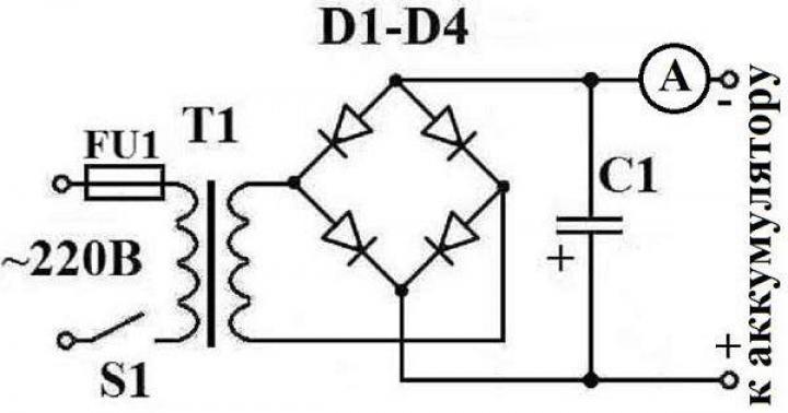
![]() To assemble the device, you can use transformers from old uninterruptible power supplies or Soviet-made TVs. Any powerful step-down transformer with a total voltage set on the secondary windings of approximately 25 volts will do.
To assemble the device, you can use transformers from old uninterruptible power supplies or Soviet-made TVs. Any powerful step-down transformer with a total voltage set on the secondary windings of approximately 25 volts will do.
The diode rectifier is assembled on two KD 213A diodes (VD 1, VD 2), which must be installed on the radiator and can be replaced with any imported analogues. There are many analogues, and they can be easily selected from reference books on the Internet. Surely the necessary diodes can be found at home in old unnecessary equipment.
The same method can be used to replace the control transistor KT 827A (VT 1) and zener diode D 814 A (VD 3). The transistor is installed on the radiator.
The supply voltage is adjusted by variable resistor R2. The scheme is simple and obviously working. It can be assembled by a person with minimal knowledge of electronics.
Pulse charging for batteries
 The circuit is difficult to assemble, but this is the only drawback. It is unlikely that you will be able to find a simple circuit for a pulse charging unit. This is compensated by the advantages: such blocks hardly heat up, at the same time they have serious power and high efficiency, and are compact in size. The proposed circuit, mounted on a board, fits into a container measuring 160*50*40 mm. To assemble the device, you need to understand the operating principle of the PWM (Pulse Width Modulation) generator. In the proposed version, it is implemented using the common and inexpensive IR 2153 controller.
With capacitors used, the power of the device is 190 watts. This is enough to charge any light car battery with a capacity of up to 100 Ah. By installing 470 µF capacitors, the power will double. It will be possible to charge batteries with a capacity of up to two hundred amperes/hours.
When using devices without automatic battery charge control, you can use the simplest network, daily relay made in China. This will eliminate the need to monitor the time the unit is disconnected from the network.
The cost of such a device is about 200 rubles. Knowing the approximate charging time of your battery, you can set the desired shutdown time. This ensures that the electricity supply is cut off in a timely manner. You can get distracted by business and forget about the battery, which can lead to boiling, destruction of the plates and failure of the battery. A new battery will cost much more
Precautionary measures
When using self-assembled devices, the following safety precautions should be observed:
- All devices, including the battery, must be on a fire-resistant surface.
- When using the manufactured device for the first time, it is necessary to ensure full control of all charging parameters. It is imperative to control the heating temperature of all charging elements and the battery; the electrolyte should not be allowed to boil. The voltage and current parameters are controlled by a tester. Primary monitoring will help determine the time it takes to fully charge the battery, which will be useful in the future.
Assembling a battery charger is easy even for a beginner. The main thing is to do everything carefully and follow safety measures, because you will have to deal with an open voltage of 220 volts.
For car batteries, since industrial samples are quite expensive. And you can make such a device yourself quite quickly, and from scrap materials that almost everyone has. From the article you will learn how to make chargers yourself at minimal cost. Two designs will be considered - with and without automatic control of the charge current.
The base of the charger is a transformer
In any charger you will find the main component - a transformer. It is worth noting that there are diagrams of devices built using a transformerless circuit. But they are dangerous because there is no protection against mains voltage. Therefore, you may receive an electric shock during manufacturing. Transformer circuits are much more efficient and simpler; they have galvanic isolation from the mains voltage. To make a charger you will need a powerful transformer. It can be found by disassembling an unusable microwave oven. However, spare parts from this electrical appliance can be used to make a battery charger with your own hands.
Old tube TVs used transformers TS-270, TS-160. These models are perfect for constructing a charger. It turns out to be even more effective to use them, since they already have two windings of 6.3 volts each. Moreover, they can collect current up to 7.5 amperes. And when charging a car battery, a current equal to 1/10 of the capacity is required. Therefore, with a battery capacity of 60 Ah, you need to charge it with a current of 6 amperes. But if there are no windings that satisfy the condition, you will need to make one. And now about how to make a homemade charger for a car as quickly as possible.
Transformer rewinding

So, if you decide to use a converter from a microwave oven, then you need to remove the secondary winding. The reason lies in the fact that these step-up transformers convert the voltage to a value of about 2000 volts. The magnetron requires a power supply of 4000 volts, so a doubling circuit is used. You won’t need such values, so mercilessly get rid of the secondary winding. Instead, wind a wire with a cross-section of 2 square meters. mm. But you don’t know how many turns are needed? This needs to be found out; you can use several methods. And this must be done when making a battery charger with your own hands.
The simplest and most reliable is experimental. Wind ten turns of the wire you will use. Clean its edges and plug in the transformer. Measure the voltage on the secondary winding. Let's say these ten turns produce 2 V. Therefore, 0.2 V (a tenth part) is collected from one turn. You need at least 12 V, and it is better if the output has a value close to 13. Five turns will give one volt, now you need 5*12=60. The desired value is 60 turns of wire. The second method is more complicated; you will have to calculate the cross-section of the transformer's magnetic core, you need to know the number of turns of the primary winding.
Rectifier block

We can say that the simplest homemade chargers for car batteries consist of two units - a voltage converter and a rectifier. If you do not want to spend a lot of time on assembly, then you can use a half-wave circuit. But if you decide to assemble the charger, as they say, conscientiously, then it is better to use the pavement. It is advisable to choose diodes whose reverse current is 10 amperes or higher. They usually have a metal body and a fastening with a nut. It is also worth noting that each semiconductor diode should be installed on a separate heatsink to improve cooling of its case.
Minor modernization
However, you can stop there, a simple homemade charger is ready for use. But it can be supplemented with measuring instruments. Having assembled all the components in a single case and securely fastened them in their places, you can start designing the front panel. You can place two instruments on it - an ammeter and a voltmeter. With their help, you can control the charging voltage and current. If desired, install an LED or incandescent lamp, which is connected to the output of the rectifier. With the help of such a lamp you will see whether the charger is plugged in. If necessary, add a small switch.
Automatic adjustment of charging current

Good results are shown by homemade chargers for car batteries that have an automatic current adjustment function. Despite their apparent complexity, these devices are very simple. True, some components will be required. The circuit uses current stabilizers, for example LM317, as well as its analogues. It is worth noting that this stabilizer has earned the trust of radio amateurs. It is trouble-free and durable, its characteristics are superior to domestic analogues.
In addition to it, you will also need an adjustable zener diode, for example TL431. All microcircuits and stabilizers used in the design must be mounted on separate radiators. The operating principle of the LM317 is that “extra” voltage is converted into heat. Therefore, if you have 15 V rather than 12 V coming from the rectifier output, then the “extra” 3 V will go into the radiator. Many homemade car battery chargers are made without strict outer casing requirements, but it is better if they are enclosed in an aluminum case.
Conclusion

At the end of the article, I would like to note that a device such as a car charger needs high-quality cooling. Therefore, it is necessary to provide for the installation of coolers. It is best to use those that are mounted in computer power supplies. Just pay attention to the fact that they need a power supply of 5 volts, not 12. Therefore, you will have to supplement the circuit by introducing a 5-volt voltage stabilizer into it. Much more can be said about chargers. The autocharger circuit is easy to repeat, and the device will be useful in any garage.